In this paper, a frequency tunable double band-stop resonator (BSR) with voltage control by varactor diodes is suggested. It makes use of a half-wavelength shunt stub as its conventional basic structure, which is replaced by the distributed LC block. Taking advantage of the nonlinear relationship between the frequency and electrical length of the distributed LC block, a dual-band device can be designed easily. With two varactor diodes, the stop-band of the resonator can be easily tuned by controlling the electrical length of the resonator structure. The measurement results show the tuning ranges of the two operating frequencies to be 1.82 GHz to 2.03 GHz and 2.81 GHz to 3.03 GHz, respectively. The entire size of the resonator is 10 mm × 11 mm, which is very compact.
Many high-performance radio frequency (RF) and microwave circuits are required these days for electronic systems. Attention has been given to low cost, miniaturized, multi-band, and frequency tunable propriety. A microstrip structure is cheap, easy to fabricate, and easy to be integrated into an electronic system. For size reduction, some novel topologies are applied [1, 2], and some metamaterial related composite right/left-handed (CRLH) transmission lines are used [3-5]. Multi-band devices are playing an increasingly important role in integrated circuits, as it can be realized for multi-functions without increasing the physical size significantly [6, 7]. For tunability, varactor diodes are used in many designs [8, 9].
In this paper, a compact frequency tunable dual-band band-stop resonator (BSR) is presented. The proposed resonator takes use of a distributed LC block structure as a shunt part of the circuit. The proposed resonator is compact and tunable, and its entire size is 10 mm × 11 mm with tunable doubleresonant frequencies of 1.82 GHz to 2.03 GHz and 2.81 GHz to 3.03 GHz.
This paper is divided into the following parts. In Section II, the resonator design and the instruction are proposed; in Section III, the simulation and measurement results are discussed; and the conclusion will follow in the last section.
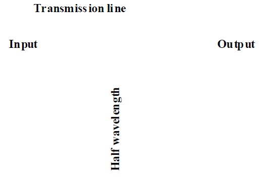
The resonator designed in this paper is based on a kind of shunted half-wavelength transmission line with a short stub, as shown in Fig. 1. The resonance condition is reached when its electrical length
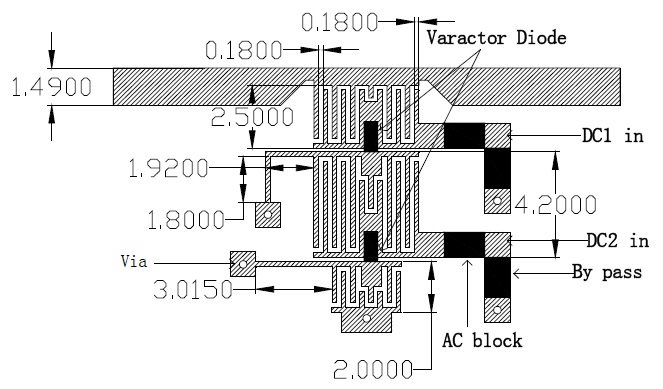
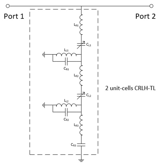
Fig. 2 shows the geometry of the proposed resonator, and Fig. 3 shows the related equivalent circuit. The distributed elements are added in Fig. 3 (
In this shunt structure, as shown in Figs. 2 and 3, two interdigital capacitors and varactor diodes with bias voltages act as tunable capacitive components (
The capacitance of the capacitors
III. SIMULATION AND EXPERIMENT RESULTS
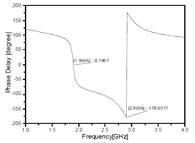
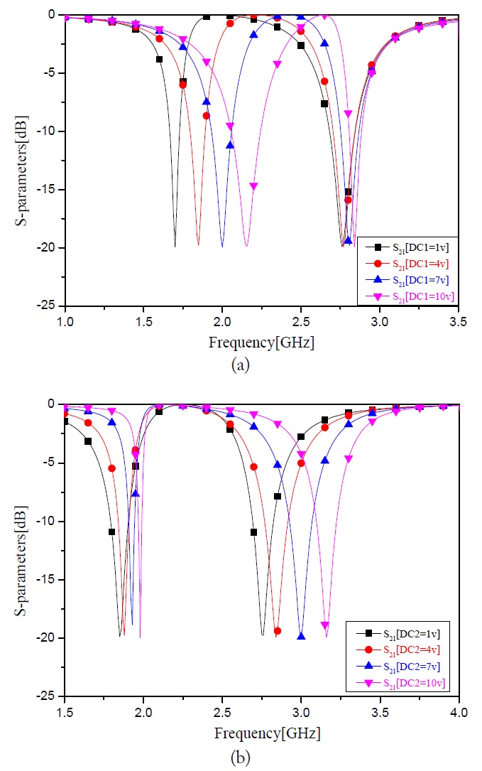
The simulations are carried out using ADS 2012 and AWR simulation software. The simulation results are shown in Fig. 5. Fig. 5 shows the
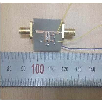
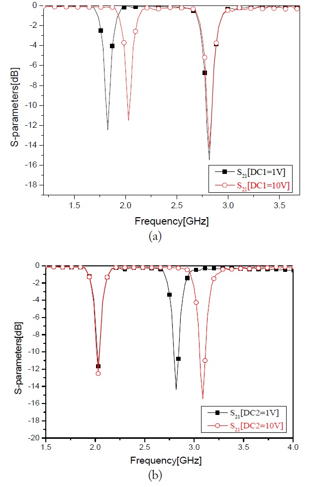
A photograph of the proposed resonator is shown in Fig. 6. The two lighter wires connect to two DC supplies and the darker wire is to be connected to the ground. An Agilent vector network analyzer (VNA) is used to measure the resonator. All measurement results are listed in Table 1. For comparison, some of the DC supply conditions are picked and their
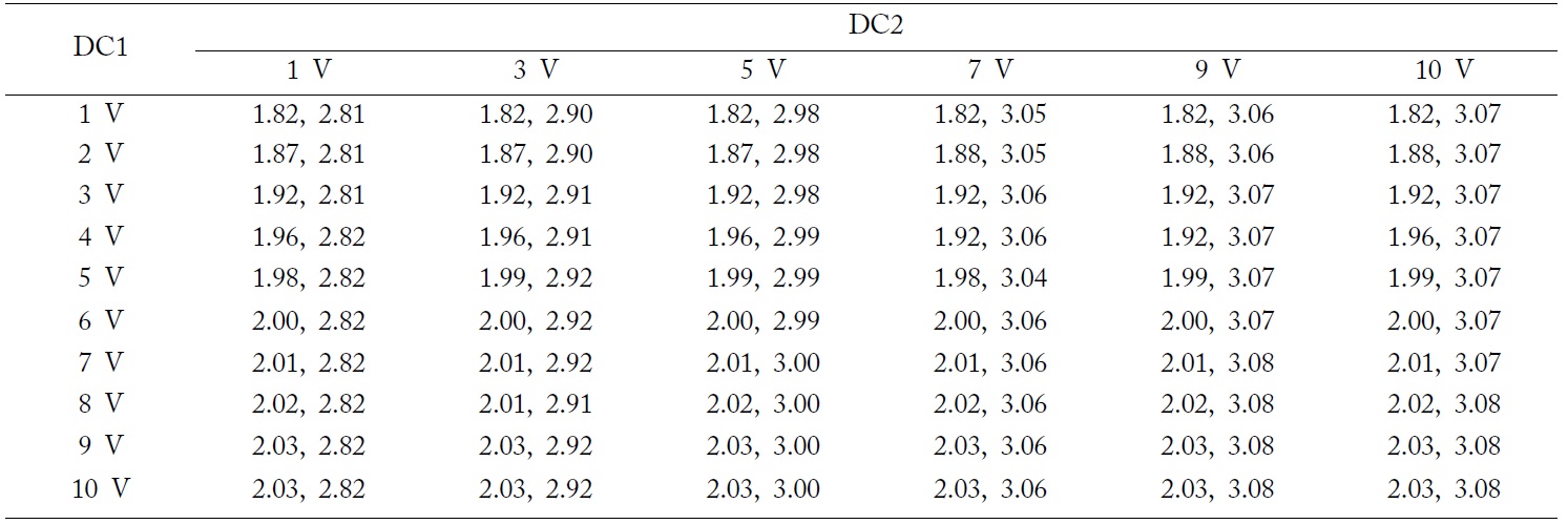
[Table 1.] Measured operating frequencies with the tuning of DC supplies

Measured operating frequencies with the tuning of DC supplies
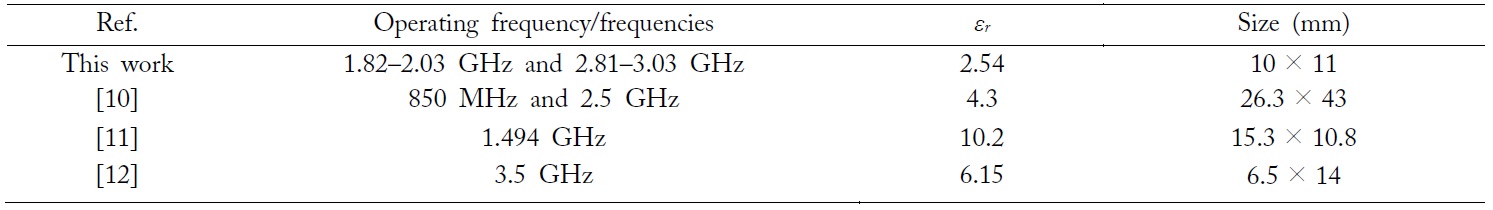
[Table 2.] Size comparison between the proposed resonator and other works

Size comparison between the proposed resonator and other works
In this paper, a compact tunable dual-band BSR has been proposed. The shunt stub with a distributed LC block can be achieved for a tunable property in the frequency response. By setting the input voltages (from 1 V to 10 V) of the two ports, the operating frequency band can be easily tuned with a good frequency rejection. The simulation and the experiment results are in good agreement. This proposed resonator is compact and may achieve a self-tuning function with proper feedback when used in microwave circuit systems.