An intelligent Wireless eXpress (WiX) system with dual power mode (low power and high power) and multi-band (bands #1, #2, and #3: band group 1) is the best solution for WVAN technology because of its low power consumption and high potential for commercial CMOS products. Using multi-band (3 bands: band group 1) and WiMedia UWB PHY data rate extension (DRE) technology, maximum ultra-high speed wireless transmission of 3 Gbps is possible. The frequency range of the three bands is 3,168–4,752 MHz and each band has a 528-MHz bandwidth, which is the same as the WiMedia UWB bandwidth [1–3]. An output multiplexer (OMUX) is used to combine the multiple frequency bands of a signal in a transceiver. It consists of channel filters, a manifold, and a wide-band antenna. The OMUX should guarantee no signal distortion at each band and high isolation from the near channels to maintain the quality of the communication.
In this paper, we have proposed a three-channel OMUX combined with an UWB antenna. The design procedure is as follows: first, we have designed the band-pass filter using an inner rectangular loop [4], an outer open stub [4,5], and a defected ground structure (DGS) [6]. To improve the insertion loss of the proposed band-pass filter, the inner rectangular loop is inserted into the outer open loop. According to the simulations, the center frequency of the band-pass filter can be controlled by changing the geometry of the outer open stub. The outer open stub can also suppress the harmonics of the bandpass filter [7]. Second, we have designed UWB antenna by modifying that of [8]. Finally, we have integrated the UWB antenna with the three-channel OMUX on a single dielectric substrate. The simulations were conducted by an Ansoft highfrequency structure simulator (HFSS). The measured results of the fabricated prototype are given with the simulated results. We also have measured the return loss, insertion loss, radiation patterns, and antenna gain.
II. BAND-PASS FILTER DESIGN AND SIMULATED/MEASURED RESULTS
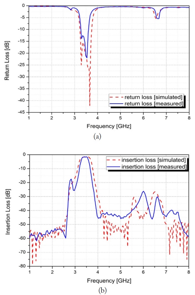
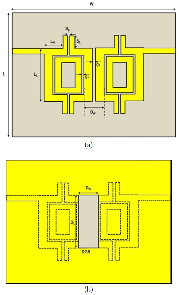
Fig. 1 shows the geometry of the proposed band-pass filter for OMUX [7]. The proposed band-pass filter has dimensions of 26 mm × 25 mm and the dielectric substrate has a height of 0.8 mm and a relative dielectric constant of 4.5 (Rogers-TMM4). The band-pass filter is excited by a 50-Ω feed line with a line width of 1.5 mm. The center frequency of the bandpass filter is 3,432 MHz and the bandwidth is 528 MHz. In this design, we have used three techniques: inner rectangular loop, outer open stub, and DGS. The inner rectangular loop and DGS are used to improve the insertion loss and the outer open stub is used to control the center frequency of the band-pass filter. The length of the outer open stub is almost a half wavelength at the center frequency. The optimal design parameters are chosen as
III. THREE-CHANNEL OMUX DESIGN USING BAND-PASS FILTER AND UWB ANTENNA
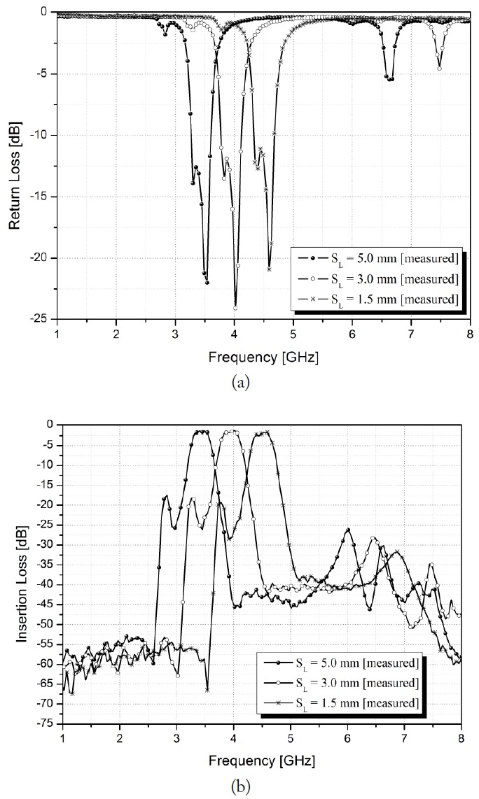
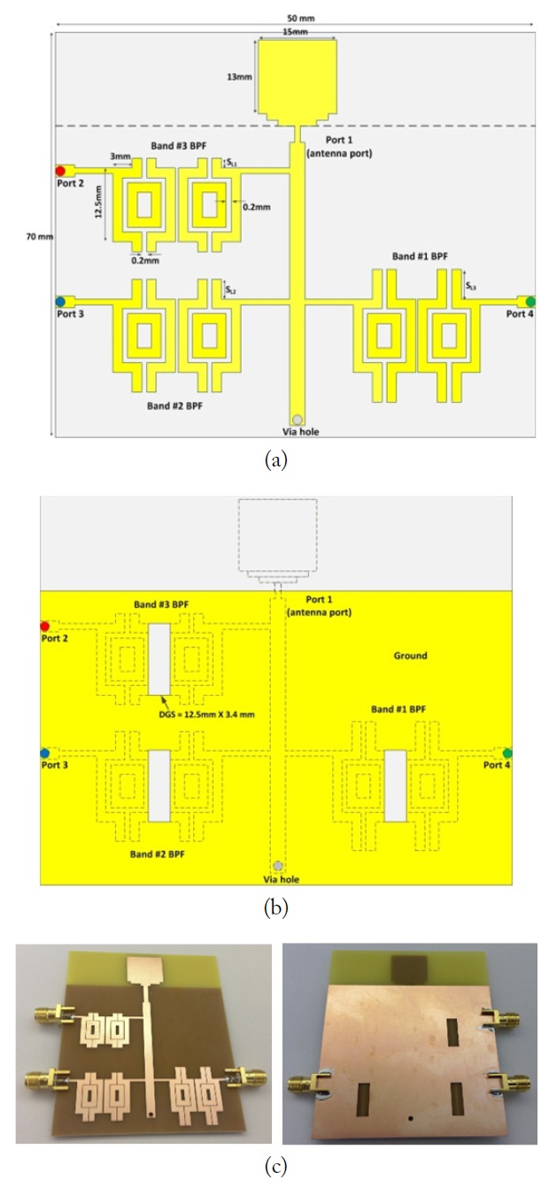
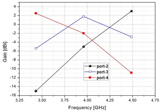
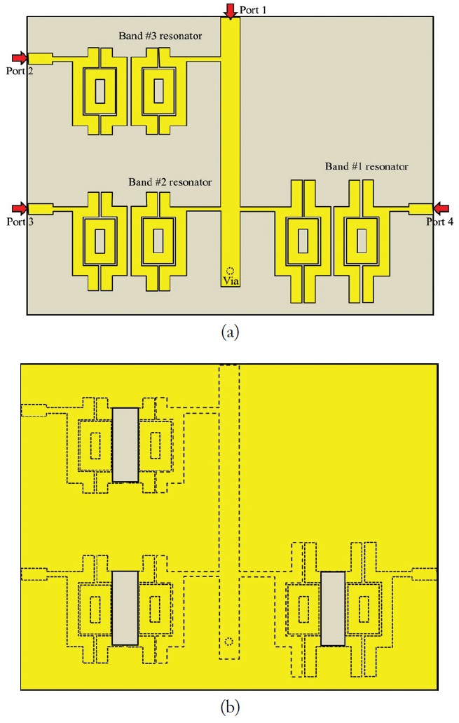
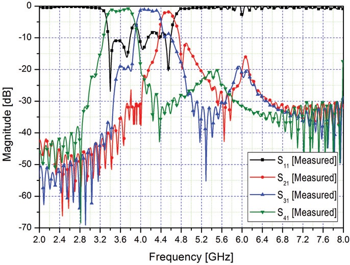
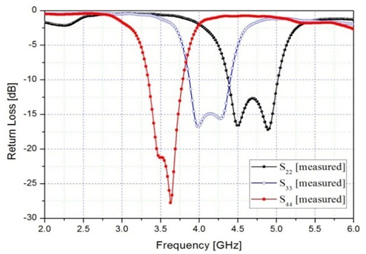
Fig. 4 illustrates the three-channel OMUX design using the proposed band-pass filter and a manifold. The proposed three-channel OMUX has four ports. Port 1 is the antenna input and other three ports are for the multi-band of the WiX system. The three-channel OMUX has the dimensions of 64 mm × 50 mm and the dielectric substrate is the Rogers-TMM4 (height = 0.8 mm, relative dielectric constant = 4.5). The basic geometry of each band-pass filter is the same and only the length of the outer open stub is different at each center frequency. In this design, the length of the outer open stub is 5, 3, and 1.5 mm, respectively. In the manifold design, we have used the microstrip line and one via hole for the impedance matching and isolation among the three bands. The isolations among the 2, 3, and 4 ports are –20, –30, and –45 dB, respectively. Fig. 5 presents the measured results of the proposed three-channel OMUX. The measured bandwidth can cover the multi-band of the WiX system (3.168–4.752 GHz). The measured insertion loss is less than 1.5 dB.
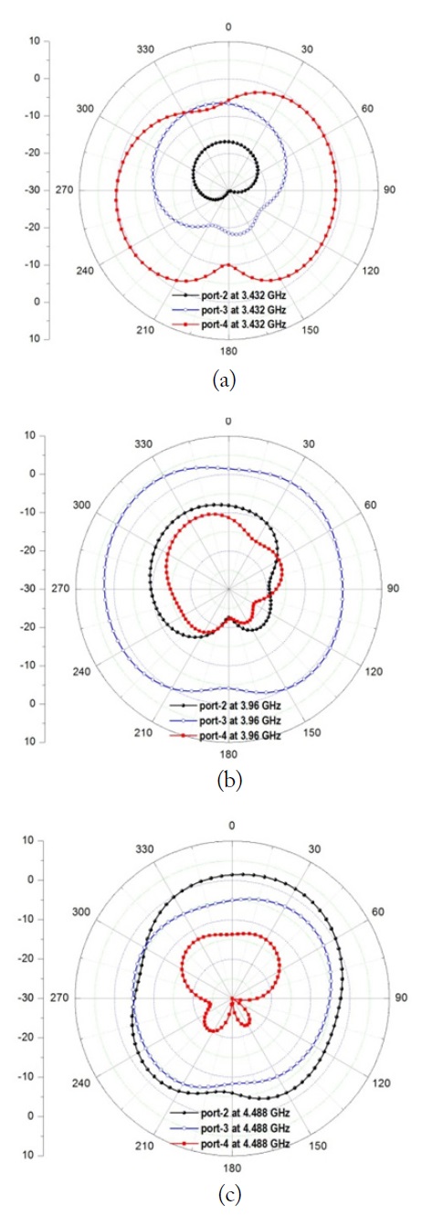
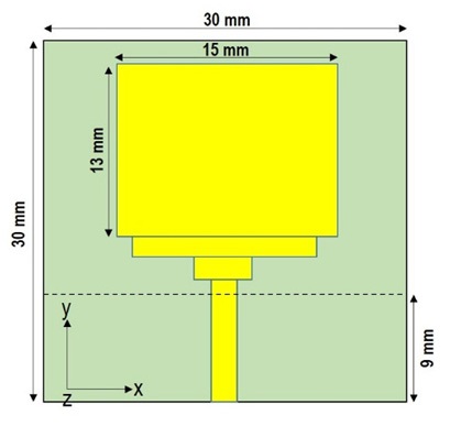
Fig. 6 shows the UWB antenna geometry of the three-channel OMUX. We have designed this antenna by modifying the UWB antenna of [8]. The size of the UWB antenna is 30 mm × 30 mm and the same substrate (Rogers-TMM4) is used for the UWB antenna design. The proposed UWB antenna consists of a rectangular patch, two matching steps (12 mm × 1 mm and 4 mm × 1 mm), and a partial ground plane. The designed UWB antenna characteristics are similar with those in [8]. The UWB antenna can cover the entire UWB system from 2.8 GHz to 10.5 GHz. The radiation patterns are similar to those of a dipole antenna.
Finally, we have integrated the UWB antenna with the three-channel OMUX. The geometry of the three-channel OMUX including the UWB antenna is shown in Fig. 7. Fig. 8 illustrates the measured return loss and antenna gain of the integrated OMUX. The measured impedance bandwidths (
A compact three-channel OMUX combined with the UWB antenna is designed, fabricated, and characterized for the WiX multi-band system. First, we have designed a compact bandpass filter using the inner rectangular loop, the outer open stub, and DGS. Next, we have designed a three-channel OMUX using the proposed band-pass filters and a manifold for the WiX system. Finally, we have integrated the three-channel OMUX with an UWB antenna. The designed three-channel OMUX has good impedance matching at each band and has the radiation pattern of a conventional UWB antenna. Thus, the proposed three-channel OMUX can be used for the WiX multi-band system.

![Geometry of the proposed band-pass filter [7]: (a) top plane and (b) bottom plane.](http://oak.go.kr/repository/journal/20409/E1ELAT_2016_v16n2_100_f001.jpg)