We live in a world of wireless communication, where huge amounts of information are transferred between mobile terminals. With the growing demand for wireless transfer of electric power, wireless power transmission (WPT) technology has become increasingly important. In 2007, a magnetically coupled WPT was first investigated by Soljacic and his research group at Massachusetts Institute of Technology [1]. They successfully lit a 60-W bulb at a distance of 7 feet—more than 2 m using helical coils of high Q-factor (= ω0L/R). Since then, numerous papers have investigated theoretical [2,3] and practical [4,5] evolutions of WPT systems. The transfer efficiency of WPT systems has been well known to depend on the figure of merit, defined as the product of the Q-factor (the geometric mean of Q1 and Q2) and the coupling coefficient (k), and the load resistance. The Q-factors of the coils are determined by the dimensions and structures of two resonators. Therefore, the coupling coefficient (k) remains to be the most important parameter to be determined carefully and accurately.
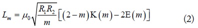
The mutual inductance (Lm), expressed as the product of the coupling coefficient (k) and self-inductance (L) (actually, the geometric mean of L1 and L2) have been usually calculated based on the Neumann integral, which can be expressed as an integral of the Bessel function or complete elliptic integrals [6–9], given by
and
where
R1 and R2 are radii of two loops. d is the distance between two loops. The calculation of the mutual inductance between inclined circular coils is also provided in [6,9]. A method of extracting the coupling coefficients (or mutual inductance) was suggested in [10]. These expressions have been found to agree well with the results extracted with [10].
In this paper, alternative analytic expressions for the mutual inductance and the coupling coefficient are presented. The new expressions consist of geometric parameters of the loops. Specifically, the coupling coefficient in this work is more explicitly expressed as a function of structure dimensions normalized to the radius of a transmitting loop, which is indeed the nature of the coupling coefficient. Based on the presented expressions, various aspects of the coupling coefficients, including the regions of positive k, zero k, and negative k, are examined with their impacts on WPT transfer efficiency. Comparisons with other expressions are also performed.
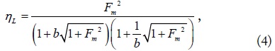
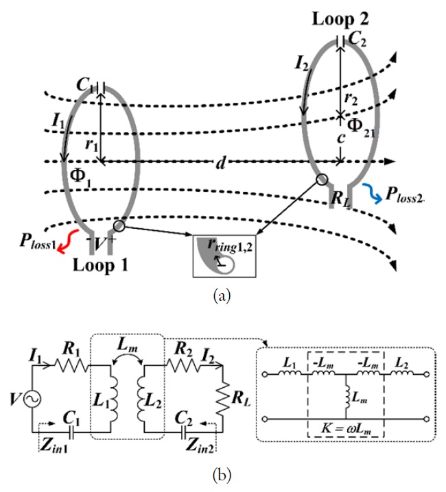
Fig. 1(a) and (b) show a WPT system consisting of two resonant loops magnetically coupled with each other and its equivalent circuit. When each loop is resonant at a resonant angular frequency (ω0), the current on each loop can be easily obtained. Details can be found in [10]. One compact but meaningful expression for the power transfer efficiency was obtained as
where Fm and b are the figure of merit of the WPT system and a load deviation factor, defined by and b = RL/RL,opt, respectively. When b = 1 in (4) [10], maximum efficiency is achieved. When b > 1, the WPT system is in the under-coupled region. When b < 1, the WPT system is in the over-coupled region. It is also notable that ηL(b) = ηL(1/b) as shown in (4).
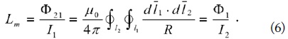
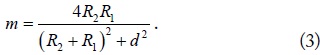
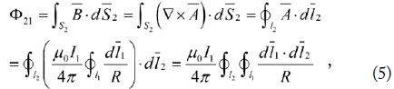
In Fig. 2, the magnetic flux Φ21 crossing the opened secondary loop (I2 = 0) due to the current I1 on the primary loop is readily obtained by converting the surface integral to a line integral, and is given by [7]
where is the magnetic flux density and is the magnetic vector potential, is the differential surface vector on S2, is the differential line vector on the secondary loop, and the other symbols are similarly defined. The mutual inductance (Lm) is defined by
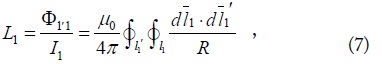
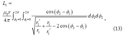
This is the well-known Neumann integral for the mutual inductance. The self-inductance of the primary loop (L1) is given by
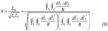
where l1' is the closed circle with radius r1' (slightly smaller than r1) and the self-inductance of the secondary loop (L2) is similarly defined [7]. The theoretical coupling coefficient between the two loops is then given by
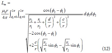
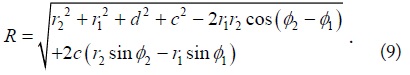
We attempt to obtain a more tractable expression in terms of r1, r2, d, and c. The distance between the source on the primary loop and field on the secondary loop is given by
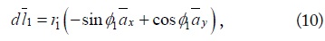
The differential line element is given by
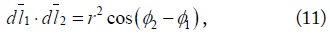
with similarly expressed. The dot product of the and is expressed as
where r is the geometric mean of r1 and Lm and the L1 can be expressed as
and
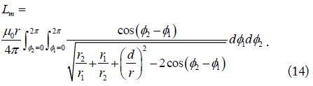
and L2 can be expressed similarly. If two loops are coaxially aligned (c = 0), Lm is simplified to
This expression is quite exact as others since it started from the Neumann integral.
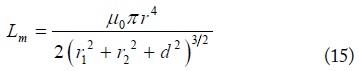
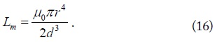
For the very special case in which d is very large (d ≫ r1, r2), the closed-form formulas for the mutual inductance of a coaxial case were given by [2,7]
and
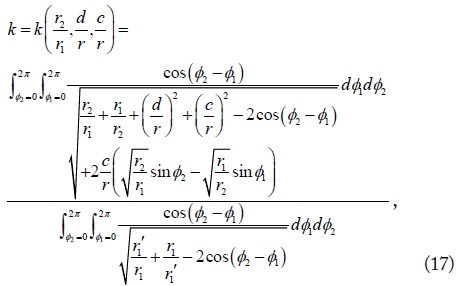
Under the assumption that r1' ≈ r1 and r2' ≈ r2 (filamentary loops) and r1'/r1 = r2'/r2, coupling coefficient (8) can be finally expressed as
where r is the geometric mean of r1 and (17) has been found to be exactly the same as the coupling coefficients in [8,9] but can serve as a convenient alternative expression written in terms of structural dimensions normalized to the radius of the transmitting loop r1 (r2/r1, d/r, and c/r). This indicates that if the ratios r2/r1, d/r, and c/r remain to be the same, the coupling coefficients are the same irrespective of the real sizes of r2, d, and c. Of course, this holds true when r2, d, and c are very small compared with the wavelength, which is usually very large at WPT frequencies. For example, at 6.78 MHz, the wavelength is approximately 44 m.
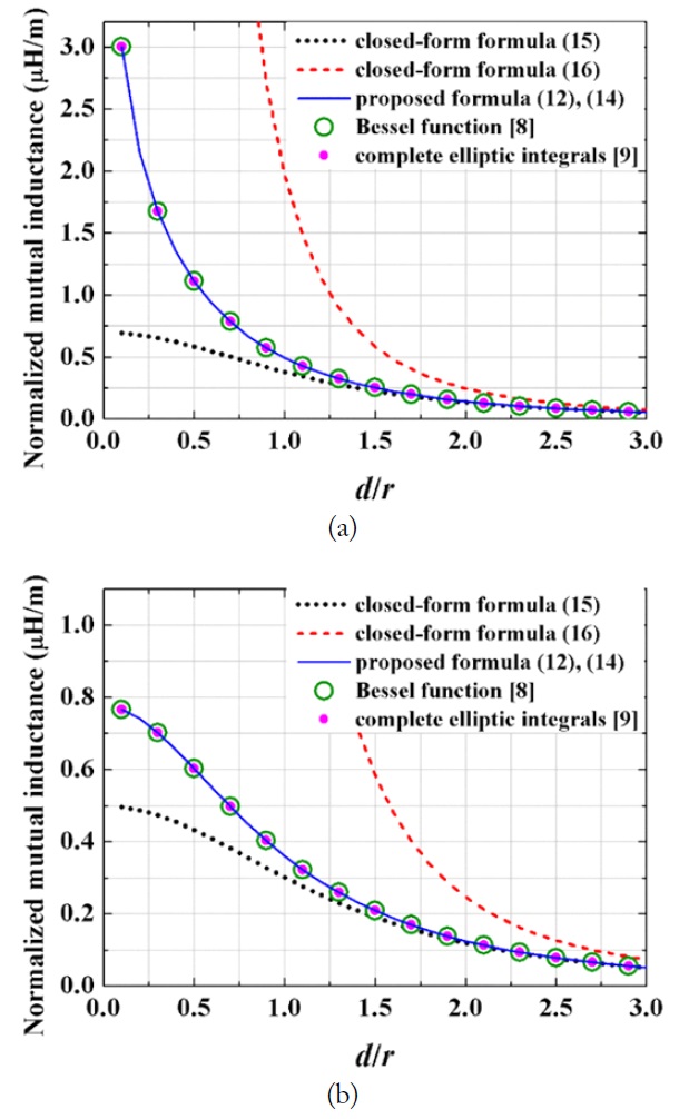
We compared the normalized mutual inductance (Lm/r) given by (14) with (15) and (16) for the coaxial cases of r2/r1 = 1 in Fig. 3(a) and r2/r1 = 0.5 in Fig. 3(b), respectively. The expressions in [8] and [9] were also included for comparisons. The results based on (14) (or (12)), [8] and [9] are shown to be in excellent agreement (and exact). The results based on (15) and (16) show large discrepancies when d/r is small. Thus, (15) and (16) are not recommended for near-field WPT problems.
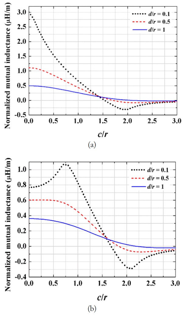
Fig. 4(a) and (b) show the normalized mutual inductances (Lm/r) between two circular loops as a function of c/r for fixed d/r = 0.1, 0.5, and 1. The cases of r2/r1 = 1 and 0.5 are shown in Fig. 4(a) and (b), respectively. As c/r increases, the mutual inductances are all shown to converge to zero as expected. It is also observed that when c/r is about 2, negative mutual inductance becomes more pronounced as d/r decreases. The negative mutual inductance simply means that the net magnetic flux in loop 2 is crossing downward. The peak when c/r is about 0.75 for the case of r2/r1 = 0.5 in Fig. 4(b) is due to the fact that the magnetic flux from loop 1 is the strongest near the loop itself not at the center. The sign of the mutual inductance is not important for the two-loop WPT system, because even though the direction of the current on loop 2 may change, the efficiency remains the same. However, it does matter for the multiple-input and multiple-output (MIMO) systems.
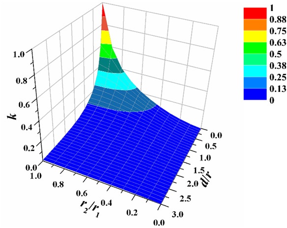
Fig. 5 shows k (17) as a function of r2/r1 and d/r with r2/r1 ≤ 1 assuming c = 0. Again, r is the geometric mean of r1 and r2. Based on the property due to reciprocity theorem, Fig. 5 covers all possible combinations of r1, r2, and d if a rule is made that r1 is the larger of r1 and r2. Eq. (17) holds true as long as r1, r2, and d are much smaller than the wavelength. The coupling coefficients are shown to monotonically decrease as r2/r1 decreases and d/r increases.
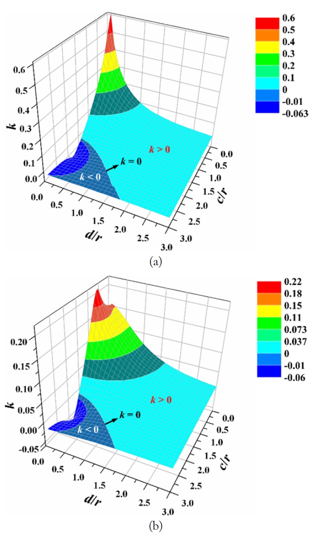
Fig. 6(a) and (b) show the coupling coefficients (17) for the cases of r2/r1 = 1 and 0.5, respectively, as a function of d/r and c/r. As explained in Fig. 5(a) and (b), the negative coupling coefficients are shown to be most pronounced when d/r is very small and c/r is about 2. For the case of r2/r1 = 0.5 shown in Fig. 6(b), the maximum coupling coefficient occurs when d/r approaches zero and c/r is about 0.5.
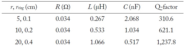
We examine the coupling coefficients and the transfer efficiencies of the WPT systems consisting of two resonant loops as examples. Three kinds of loop structures are employed. The radii of the loops are 5 cm, 10 cm, and 20 cm, respectively. In Table 1, the values of R, L, C, and Q-factor are summarized for the three loops. Each loop is made of copper with σ = 5.8 × 10⁷ S/m. The chip capacitors are loaded on the loops for a resonance at 6.78 MHz. The Q-factors of the loops have been calculated to be 334.2 (r = 5 cm), 668.3 (r = 10 cm), and 1,331.9 (r = 20 cm).
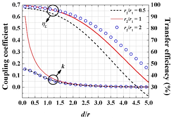
Fig. 7 shows the coupling coefficients and transfer efficiencies as a function of d/r for the cases of r2/r1 = 0.5, 1, and 2. The radius of the primary loop (r1) is fixed at 10 cm. The coupling coefficients for the case of r2/r1 = 1 are shown to be larger than those of the other cases. The higher efficiency for the case of r2/r1 = 2 compared to the case of r2/r1 = 0.5 is due to the larger Q factor, because the coupling coefficients remain the same.
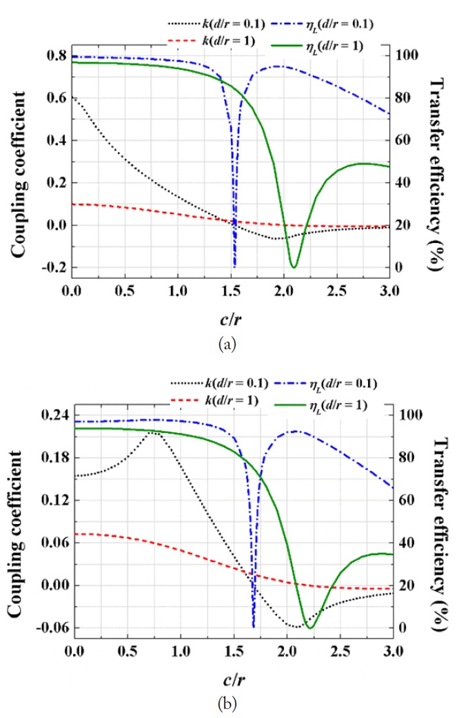
Fig. 8(a) and (b) show the coupling coefficients and transfer efficiencies as a function of c/r with different d/r’s of 0.1 and 1 for the cases of r2/r1 = 1 and 0.5. For the case of r2/r1 = 1 and d/r = 0.1, the coupling coefficient changes sign from positive to negative when c/r is about 1.5. Near this position, the 80% efficiency is shown to drop abruptly to zero but then to quickly recover to a value above 70%. A similar phenomenon is observed for the case of r2/r1 = 1 and d/r = 1 but the efficiency recovers to about 50%. For the case of r2/r1 = 0.5, similar effects are demonstrated, but the levels of the results are smaller than those for the case of r2/r1 = 1.
This paper presents alternative analytic expressions for the mutual inductance and coupling coefficient between circular loops. The mutual inductance and coupling coefficient have been expressed in more familiar forms and explicitly written in terms of structure ratios and the placement of loops. Various aspects of the coupling coefficients, including the regions of positive k, zero k, and negative k, have been examined respect to with their impacts on WPT transfer efficiency.