Since Pendry et al. [1] introduced the split ring resonator (SRR) to construct an effective medium with negative permeability, a variety of research activities has been conducted. In [2], the electromagnetic fields generated from a source can be focused to a point using a fat lens characterized by an effective μr = –1 (realized by SRR) and εr = –1 (realized by thin wires [3]) medium. In the magnetostatic and electrostatic limits, the μr = –1 slab and the εr = –1 slab can do the same, respectively. Specifically, quasi-static longitudinal magnetic fields from a magnetic point source can be focused by a μr = –1 slab, and quasi-static longitudinal electric fields from an electric point source can be focused by an εr = –1 slab. The artificial periodic structure consisting of SRRs and thin wires was experimentally verified to have the property of negative refraction among others [4]. Isotropic bulk metamaterials were introduced [5] and developed [6]. A review paper [7] on bulk metamaterials made of resonant rings was also published. Although many applications have been made on transmission line-based metamaterials [8–10], bulk metamaterials have been only applied in cloaking [11], magnetic resonance imaging (MRI) [12–14], and wireless power transfer [15]. The usefulness of the metamaterial slab was demonstrated experimentally by comparing the MRI images with and without it [13]. Despite the many promising features of bulk metamaterials, their narrow band and relatively high loss inherent in SRRs prevent their rapid progress. As presented in [2], although considerable focusing is achieved, the imaginary part of the dielectric function prevents an ideal reconstruction.
In this work, we investigate the degree of these limitations in a systematic and quantitative manner. In particular, the capacitively loaded ring resonators (RRs) initially introduced by Schelkunoff and Friis [16] are analyzed in terms of their bandwidth and loss. First, the effective permeability is expressed as a function of structural factors of the resonator relative to the used wavelength. Using this expression, the characteristics of the medium are examined over a wide frequency range, especially in terms of the newly defined mu-negative bandwidth and losses on RRs. Simple and convenient design equations are then derived by inverting the analysis equations. Some examples are also provided to demonstrate the effectiveness of the formulation.
A natural magnetic material such as ferrite has long been modeled as a bulk structure consisting of many magnetic dipole moments (ms) [17], which are defined as a product of a spin current and a spin area on an atomic or a molecular scale. Magnetization (M) is then defined as their vector sum divided by a volume containing them. The effective medium concept, which replaces the particle behaviors on a microscopic scale with a simple effective permeability on a macroscopic scale, is a useful and reliable model when the wavelength is much larger than the particle dimensions. This conventional and familiar procedure can be extended to the problem of artificial effective medium consisting of magnetic particle-like RRs.
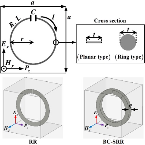
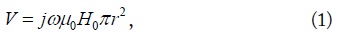
Fig. 1 shows the unit of the artificial effective medium composed of many RRs. The RR is chosen instead of the SRR for its simple modeling. Similar effects are expected for SRRs. The details of the RR and its orientations with respect to an incident TEM wave are depicted in Fig. 1. The wave travels in the z direction with the electric and magnetic fields oriented in the x and y directions, respectively. In this work, only the coupling of the magnetic field Hy leading to a relative effective permeability is considered. The side length of the unit cell is a. The radius of the RR is r, and t is the width of the planar-type RR and the diameter of the ring-type RR. The chip capacitor is represented by C. It is inserted for the resonance of the RR, which has an inductance (L) roughly proportional to r. The total resistance (R) of the RR is the sum of the ohmic resistance and the radiation resistance. The radiation resistance is negligible when r is much smaller than the wavelength. The modeling of RRs was already developed in [6,17], but it is briefly outlined here. Let Hy = H0 be the incident (or applied) magnetic field. Then, the induced phasor voltage to let the current (I) flow in the reference direction (Fig. 1) is given by
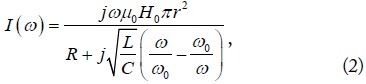
where μ0 is the free space permeability, and ω is the angular frequency of the incident fields. The induced current (I) in Fig. 1 is determined by
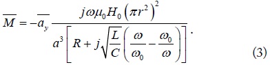
where ω0 is the resonant angular frequency given by is the reactance slope parameter related to the bandwidth of the induced magnetism. The definition of magnetization (M) [18], which has long been used for natural magnetic materials, can still be applicable to artificial bulk metamaterials made of RRs when the side length of the unit cell (a) is much smaller than the wavelength. It is expressed as
When R = 0, the magnetization (3) due to the current (2) is in the same direction (paramagnetism) as that of the incident magnetic field when ω < ω0, and the opposite (diamagnetism) is true when ω > ω0. A well-established constitutive relation is given by
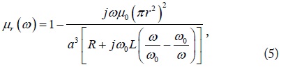
where B is the magnetic flux density and χm is the magnetic susceptibility. The relative effective permeability (μr) is obtained as
where ω0L is also the reactance slope parameter.
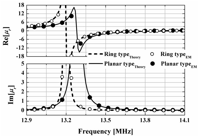
Fig. 2 shows the real and imaginary parts of the relative effective permeability for the RRs presented in Fig. 1 obtained using (5) and an extraction method [19] based on EM-simulated S-parameters. Two types (planar type and ring type shown in Fig. 1) of typical RRs with a = 12 cm, r = 3.5 cm, and t = 1 cm are considered. They have been designed to have μ′ = –1 at 13.56 MHz by a trial and error method. The EM-based extracted [19] effective permeability is shown to be in excellent agreement with (5), thus validating the derived expression (5). At the same frequency of 13.56 MHz, μ′′ = 0.2 for the planar type and μ′′ = 0.04 for the ring type.
Here, we intend to analyze the bulk metamaterials made of RRs in terms of the effective medium in a more systematic manner. The ring-type RR is considered first. When a < 0.1λ0, the radiation resistance is much smaller than the ohmic resistance, and R can be approximated as [18].
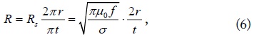
where σ is the conductivity, Rs is the surface resistance per square, and 2r/t is the aspect ratio of the ring-type RR (Fig. 1). The only difference in the planar-type RR is that its aspect ratio is π times larger than that of the ring-type RR. The inductance of the ring-type RR is expresses as [18].
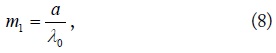
The implication here is that if t becomes relatively large for a fixed r, L and the slope parameter ω0L in (5) decrease and result in a larger bandwidth. To analyze (5) in detail, define
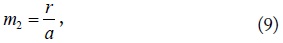
where λ0 is the free space wavelength at the resonant frequency (f0),
which must be reasonably greater than 0 to have the effect of diamagnetism and less than 0.5 to prevent a contact with an adjacent RR unit, and
where t must be smaller than 2(a/2 – r) but is not recommended to be very small because it increases losses of the medium. The may be called structural reduction factors, and m1m2m3 = t/λ0. m1 must be very small, i.e., less than 0.1, to apply an effective medium concept.
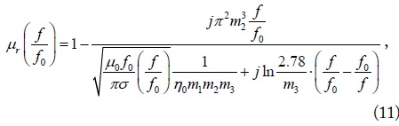
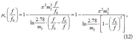
Using (6)–(10), (5) may be, as a function of a normalized frequency f/f0, expressed as
where η0 is the intrinsic impedance in free space given by The first term in the denominator may be understood as a loss-perturbing factor in a lossless effective medium. As an initial observation, for a medium with lossless RRs (σ→∞), the relative effective permeability μr is reduced to
which is purely real and independent of m1 (=a/λ0). Moreover, the functional behavior of (12) is the same irrespective of f0 once m2 (= r/a) and m3 (= t/r) are chosen.
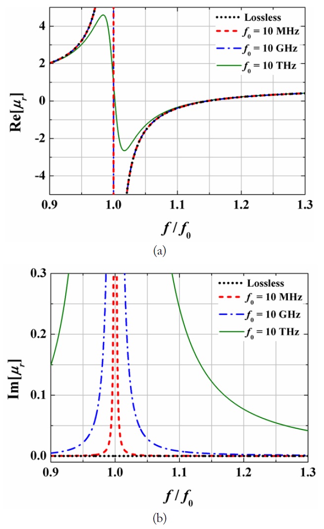
In Fig. 3, we plot the real (a) and imaginary (b) parts of (11) and (12) as a function of the normalized frequency f/f0 for the cases of different resonant frequencies f0 = 10 MHz, 10 GHz, and 10 THz, assuming that m1 = 0.1, m2 = 0.4, and m3 = 0.2. Note that Re[μr] = –1 when f/f0 is roughly 1.06 irrespective of the resonant frequency (f0). However, the imaginary parts (b) are shown to become large as the frequency increases as the loss-perturbing factor increases depending on
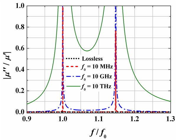
In Fig. 4, we plot the loss tangent |μ′′/μ′| of bulk metamaterials made of RRs based on the same assumption as in Fig. 3, where μ′ is the real part of the relative effective permeability and μ′′ is its imaginary part. The loss tangent is observed to have two peaks. The first one is at the resonant frequency (f0), and the second one is at the magnetic plasma frequency (fmp), where Re[μr] = 0. The loss tangent in the frequency region between f0 and fmp is shown to be relatively larger than that in other regions. Especially in the case of f0 = 10 THz, the loss tangent is approximately greater than 0.017.
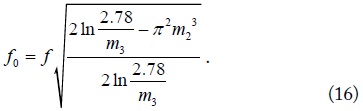
If we want to find the resonant frequency (f0) with which we have a specific relative permeability (μr) at f, by inverting (12), we obtain
This formula can be used as a design equation for a bulk metamaterial to have a negative μr at any frequency f.
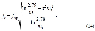
For a desired plasma frequency at fmp, f0 is obtained by
In the frequency range of f0 to fmp, μr is negative. We define the mu-negative (MNG) fractional bandwidth given by
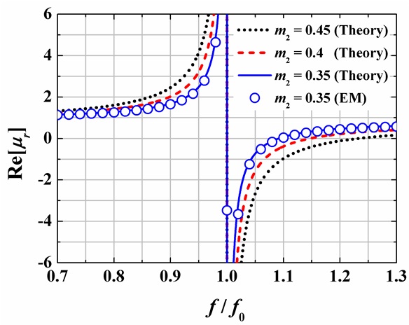
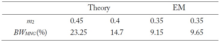
Fig. 5 presents the theoretical and EM-simulated real parts of μr as a function of f/f0 for some different values of m2 when m1 = 0.1 and m3 = 0.2. The resonant frequency (f0) of 10 GHz is used. As m2 increases, BWMNG also increases as expected in (15). The results in Fig. 5 are summarized in Table 1. When the m2’s are 0.35, 0.4, and 0.45, the theoretical BWMNG are 9.15%, 14.7%, and 23.25%, respectively. The EM-simulated BWMNG is 9.65% when m2 = 0.35. The theoretical and EM-simulated BWMNG are shown to be in good agreement.
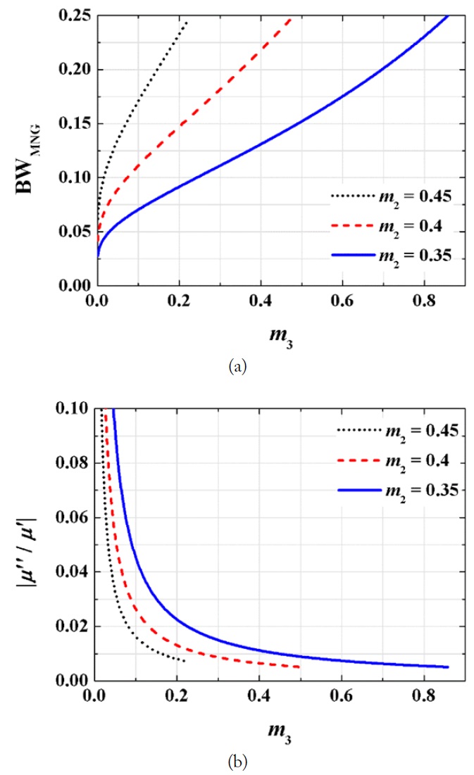
Fig. 6(a) and (b) show the MNG fractional bandwidth (BWMNG) and the magnetic loss tangent (|μ′′/μ′|) of the medium made of ring-type RRs (Fig. 1) as a function of m3 (= t/r) for different m2 (= r/a) values when f0 = 60 MHz (used for MRI) and m1 = 0.01. When the m2’s are 0.35, 0.4, and 0.45, m3 must be less than 6/7, 1/2, and 2/9, respectively, to prevent contact among the resonators. The BWMNG for each m2 is shown to considerably increase from 5% to 25% as m3 increases in the allowable range. m3 (= t/r) is shown to play an important role in the enhancement of BWMNG. The reason for this finding is that as m3 increases, the inductance (7) and reactance slope parameter in (5) substantially decrease. The loss tangent (|μ′′/μ′|) of the medium when Re[μr] = –1 also decreases because the aspect ratio in (6) decreases as m3 increases. When m2 is 0.35 or 0.4, the loss tangent is shown to be as small as 0.005.
The design Eq. (11) is used for a practical example. When an effective medium characterized by μr = –1 at f is desired, f0 is given by
If a μr = –1 medium is required at f (63.87 MHz) for MRI applications with a reasonable choice of m1 = 0.0064, m2 = 0.4, and m3 = 0.4, (16) and (7) give f0 = 58.44 MHz and L = 3.17 nH, respectively. Then, the capacitance of the chip capacitor is determined as 2.34 nF.
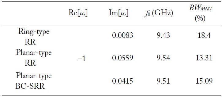
Let us take more design examples at another resonant frequency. In Table 2, we summarize the characteristics of the media composed of ring-type RR, planar-type RR, and broadsidecoupled SRR with their dimensions. The relative effective permeability is –1 at 10 GHz. The m1, m2, and m3 are 0.1, 0.4, and 0.4 at 10 GHz, respectively. Using (16), we obtained the resonant frequencies for each case. The BWMNG of the ring-type RR is wider than that of the others. In addition, the loss of the ring-type RR is smaller than the others. The presented design procedures are scalable to other frequencies.
Through the provided simple expressions of effective permeability for bulk metamaterials consisting of RRs, their characteristics have been systematically investigated by introducing some convenient geometrical factors. The MNG bandwidth and losses in the medium can be engineered for the best possible performance. The MNG bandwidth has been shown to be enhanced up to 25% by decreasing the reactance slope parameter with the possible widest width of the used RR. The loss tangent when Re[μr] = –1 has been shown to be as small as 0.005. Some convenient synthesis equations have also been derived to obtain a systematic design process with some examples.


![(a) Mu-negative fractional bandwidth (BWMNG) and (b) magnetic loss tangent of the ring-type ring resonators (|μ′′/μ′| when Re[μr] = ?1). Fixed f0 = 60 MHz and m1 = 0.01.](http://oak.go.kr/repository/journal/20406/E1ELAT_2016_v16n2_67_f006.jpg)