Since the US Federal Communications Commission allocated the frequency band from 3.1 GHz to 10.6 GHz for ultra-wide band (UWB) systems, UWB technology has attracted a great deal of interest due to its low cost, low complexity, and extremely high data rate transmission capabilities for short range communication. In addition, UWB systems are resistant to severe multipath and jamming environments [1]. However, UWB systems potentially cause interference with coexisting wireless communication systems, such as the WiMAX (3.3–3.6 GHz), WLAN (5.15–5.82 GHz), and X-band (7.9–8.7 GHz) signal bands. Therefore, UWB antennas should ideally have band notch functions.
To avoid potential interference, UWB antennas with single [2–6], dual [7–11], or triple [12–15] band rejection functions have been presented. Recently, UWB antennas with quadruple notch bands [16,17] have also been reported. However, these antennas do not have good rejection levels of peak gains in all desired notch bands. Selectively creating a narrow stop band and a wide stop band for different notch bands is challenging. For example, the WiMAX band has a relatively narrow band (300 MHz), whereas the WLAN (675 MHz), X-band (500 MHz), and ITU 8 GHz (800 MHz) bands have relatively wider bands. Therefore, establishing different ways of achieving the band rejection characteristic for each notch band is preferable.
To resolve the task of selectively obtaining the different notch band bandwidths, a trapezoidal UWB antenna with quadruple notch slots, filters, and a complementary split ring resonator (CSRR) to design the proposed band-notched characteristic considering the space limitation imposed on the antenna and band rejection elements. The proposed antenna structure is simulated using the ANSYS High-frequency Structure Simulator (HFSS), which is a commercial 3-D full-wave electromagnetic simulation program. The simulation and measurements both indicate quadruple band rejection with central frequencies of 3.5 GHz (WiMAX), 5.5 GHz (WLAN), 7.4 GHz (X-band), and 8.4 GHz (ITU 8 GHz band) with excellent quadruple band-notched characteristics.
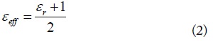
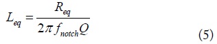
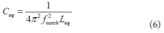
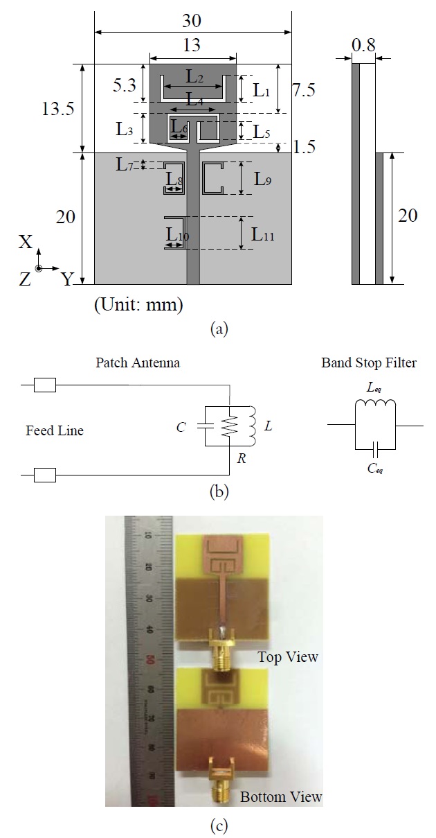
Fig. 1(a) depicts the geometry of the proposed trapezoid UWB antenna. The dimensions of the optimized antenna are shown in Table 1. The antenna is designed on an FR-4 substrate with a thickness of 0.8 mm, relative permittivity of 4.4, and a loss tangent of 0.02. The proposed antenna is fed by a 50-Ω microstrip line. The equivalent circuit of the patch antenna and the band-stop element is shown in Fig. 1(b). The proposed design is optimized by considering several aspects, such as the size of the band-stop elements, bandwidth of the antenna, bandwidth of the notch bands, level of band rejection, and radiation patterns. Considering the relatively sharp and narrow bandwidth of the notched WiMAX band, a CSRR structure is used as a band rejection element in the proposed antenna because CSRRs are electrically small RLC resonant elements with a high quality factor at microwave frequency. The length of the CSRR is
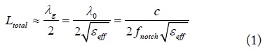

where λ0 is the free space wavelength,


[Table 1.] Optimized antenna parameters
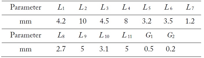
Optimized antenna parameters
where
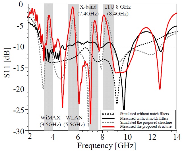
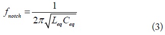
Fig. 1(c) shows a photograph of the fabricated antenna, and Fig. 2 depicts the measured and simulated
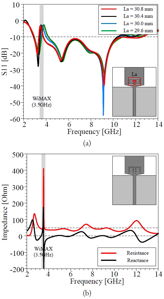
To avoid interference with the WiMAX band, a single band-notched design with a CSRR structure is presented and analyzed in this section. The band-notched characteristic at the desired frequency can be obtained by adjusting the length of the CSRR to approximately half of a wavelength. The effects of four different lengths of the CSRR
Fig. 3(b) illustrates the input impedance of the desired single band-notched structure for the WiMAX band. At a central frequency of 3.5 GHz, the imaginary component curve exhibits a parallel resonance characteristic, and the real part has a peak of around 400 Ω. The parallel resonant phenomenon opens the input terminal, so that the antenna cannot radiate efficiently at this frequency.
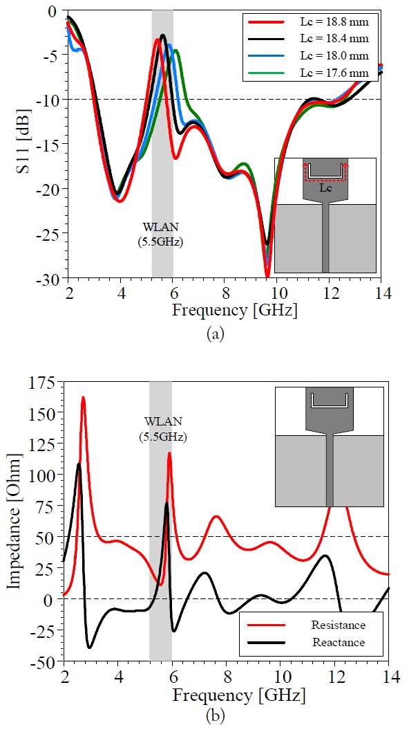
To suppress the unwanted WLAN band, a single band-notched structure with a U-shaped slot is presented and analyzed in this section. The band-notched characteristics at the desired frequency can be obtained by adjusting the length of the U-shaped slot to be approximately half of a wavelength. The effects of the key parameter corresponding to the four different lengths of the U-shaped slot
Fig. 4(b) shows the input impedance of the required single band-notched design for the WLAN band. When the frequency is 5.3 GHz, the imaginary component approaches 10 Ω. When the frequency is 5.8 GHz, the imaginary part exhibits a parallel resonance, but the real part peaks at around 120 Ω. The series and parallel resonances at 5.3 and 5.8 GHz have minor effects on the impedance matching performance. Thus, radiation performance suffers in the WLAN band because of impedance mismatching.
>
Single Notch Band for X-band Satellite Communication
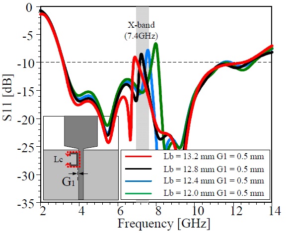
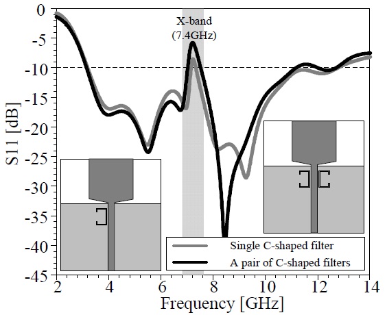
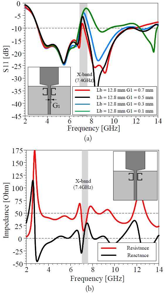
To minimize the potential interference with X-band satellite communication, a single band-notched design with a single C-shaped filter and a pair of C-shaped filters is presented and analyzed in this section. The band-notched characteristic at the desired frequency can be obtained by adjusting the length of the filter
The input impedance of the antenna with a single notch band for the X-band downlink is shown in Fig. 7(b). At 7.2 GHz, the imaginary component curve exhibits a series resonance characteristic, and the real part is close to 10 Ω. Therefore, the radiation performance deteriorates at this frequency because of impedance matching.
>
Single Notch Band for ITU 8 GHz Signal Band
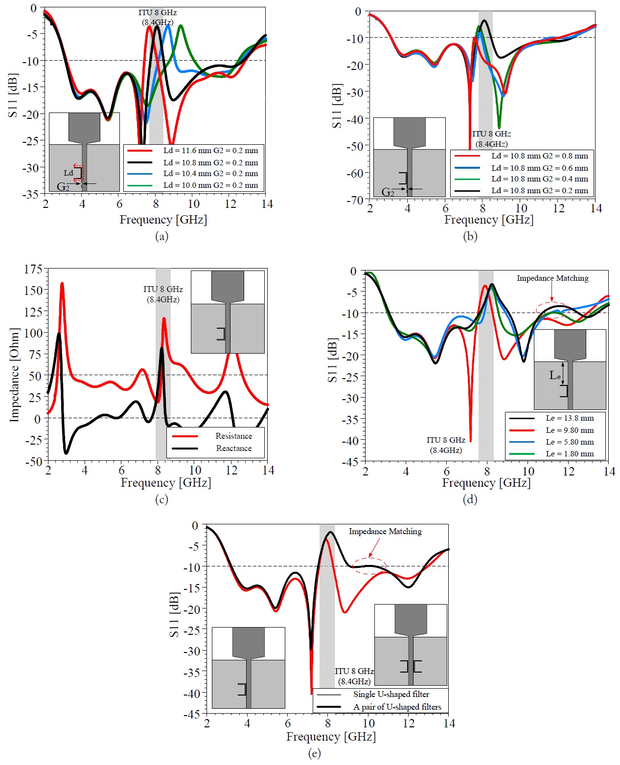
To reduce the unwanted ITU 8 GHz signal level, a singlenotched band structure with a U-shaped band stop filter is applied to a trapezoid UWB antenna. The band-notchedcharacteristic at the desired frequency can be obtained by adjusting the length of the filter
Fig. 8(e) shows the
Fig. 8(c) shows the input impedance of the single band-notched antenna. At the central frequency of 8.4 GHz, the imaginary component curve exhibits a parallel resonant characteristic, and the real part peaks at around 120 Ω. The antenna cannot radiate efficiently at this frequency because of impedance mismatching.
>
Performance of the Proposed Antenna
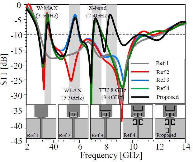
The reflection coefficient characteristics in the previous subsections show that each notch band scheme generates a notch function in the designated frequency band only, and it does not affect the reflection coefficient characteristics in other notch bands. Thus, the quadruple notch band characteristic can be realized by combining the four notch structures mentioned in the previous subsections.
Fig. 9 presents the
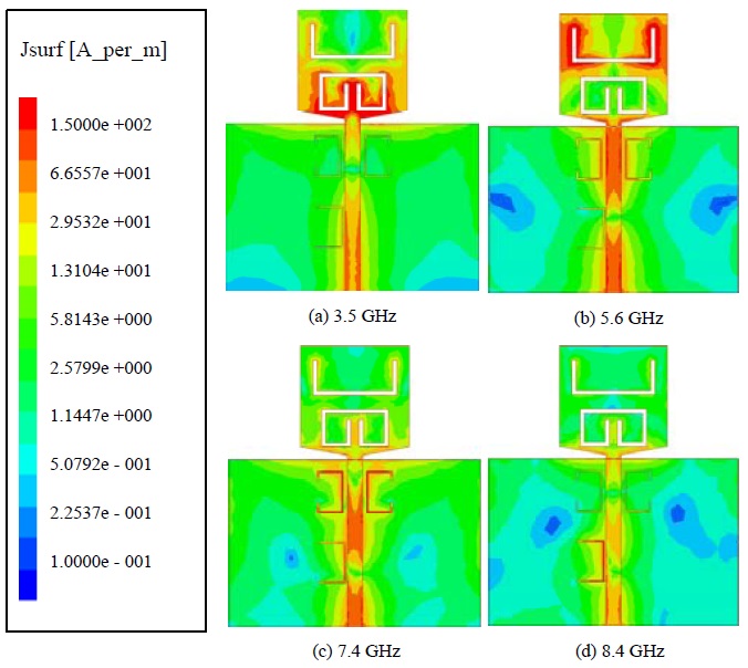
To further understand the operating principle behind this quadruple band-notched performance, the current distributions at four different notched frequencies are depicted in Fig. 10(a)–(d). The surface currents are highly concentrated near the edges of the slots and in the band rejection filters at thenotch band frequencies. At these notch frequencies, energy is stored around the band-stop elements rather than being radiated into free space.
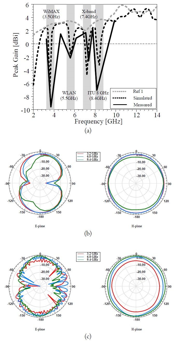
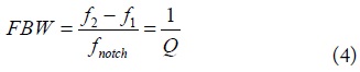
The measured and simulated peak gains of the proposed antenna are shown in Fig. 11(a). The peak gains at four different notch bands are all smaller than 0 dBi. The peak gain performance of the proposed antenna is better than that found in previous research [16,17]. One of the means to reduce the gains in a notch band is to improve the
Fig. 11(b) and (c) show the simulated and measured radiation patterns, respectively, of the proposed antenna in the E-plane and H-plane at 3.2, 6.8, and 9.4 GHz. The antenna shows omnidirectional radiation patterns in the H-plane.
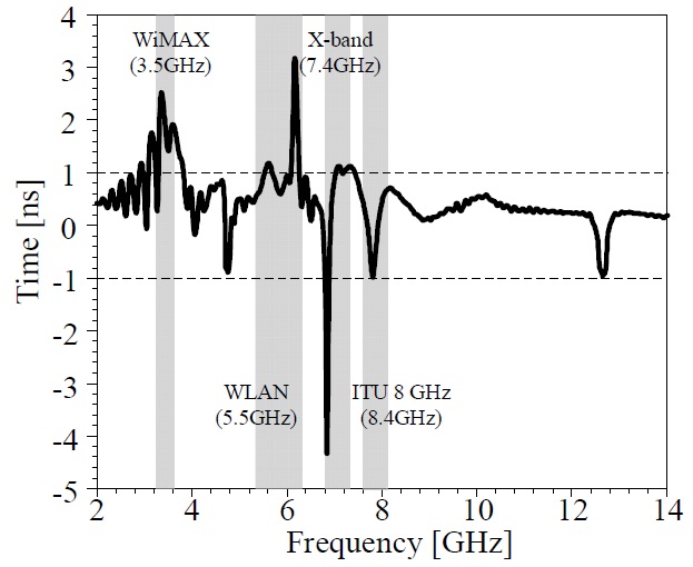
The measured group delay of the fabricated antenna is illustrated in Fig. 12. If the group delay variation exceeds 1 ns, the phases will not be linear in the far-field region. This condition causes pulse distortion bands, while the group delay variation exceeds 1 ns in the four desired notch bands. Based on the reflection coefficient, peak gain, and group delay characteristic results, the band-notched characteristic of the proposed antenna is well designed for UWB systems.
In this paper, a trapezoid UWB antenna with a quadruple band-notched characteristic is proposed to avoid possible interference with the WiMAX, WLAN, X-band downlink, and ITU 8 GHz signal bands. The simulated reflection coefficient shows that the proposed antenna realizes a band-notched characteristic in the WiMAX (3.44–3.85 GHz), WLAN (5.26–6.01 GHz), X-band downlink (7.05–7.68 GHz), and ITU 8 GHz signal bands (8.08–8.87 GHz) by properly selecting the band rejection elements. The proposed antenna attains omnidirectional radiation patterns in the Hplane and has good peak gain performance at the notch bands. Therefore, the proposed antenna is a good candidate for UWB communication with band-notched applications.