As a frequency continues to increase, the scattering parameter (
Both in analog and digital applications, many passive structures of interest are embedded between microstrip or strip lines. If one desires to characterize such structures by
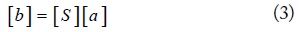
In this paper, we propose a de-embedding method for multiport networks, especially for coupled odd interconnection lines, based on the scattering matrix (
II. MULTIPORT DE-EMBEDDING TECHNIQUES FOR UNCOUPLED INTERCONNECTION LINES
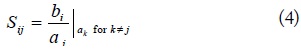
The
1. Lossless and Uncoupled Lines with Matched Load
When the load is matched to the generator,

Based on the equation obtained above, we can conclude that
2. Unmatched Load Condition Solved by Generalized S-Parameters
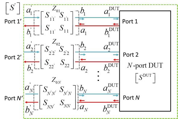
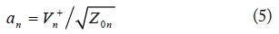
Practically, the characteristic impedances of a multiport network may be different, where the solution for the matched case is no longer applicable. Herein, a generalization of the
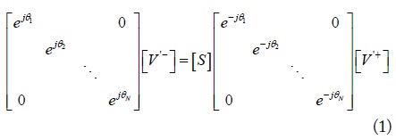
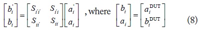
The relationship between the incident and reflected waves for an arbitrary load condition can be expressed by a generalized
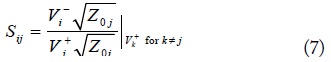
As the characteristic impedance of the interconnection lines does not equal the load, a new set of wave amplitudes is demanded, as in (5) and (6).

In the unmatched load case, a modification has been added to (4) to obtain (7), which is the
3. De-Embedding Techniques for Uncoupled Interconnection Lines
An
The transfer
In the equation above, the unprimed
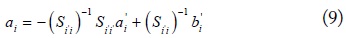
In the same way, the element
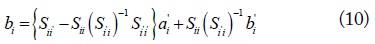
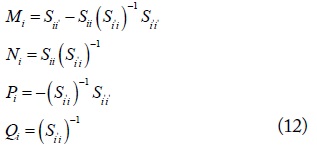
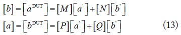
As a combination of (9) and (10), the incident and reflected waves only for the DUT are obtained as expressed in (11),
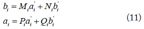
where the coefficients
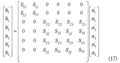
The derivations of the mentioned equations are based on a two-port network system, and calculated equations can also be represented as a matrix form, as expressed in (13), to extract the intrinsic
In this uncoupled interconnection lines case, matrices [
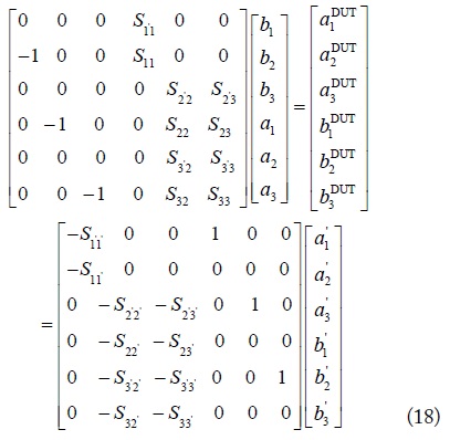
As the incident and reflected waves are difficult to measure directly, a modification has been made to (13). The
The coefficients in (14) can be both even-order and oddorder matrices, so the proposed method is appropriate for the de-embedding techniques of odd-number uncoupled ports.

The method developed in [8] is another approach for providing a solution in an odd-number case. In that reference, a general three-port de-embedding method using shield-based test structures for a microwave on-wafer characterization is presented. The surrounding parasitic of a DUT has been shielded to realize the uncoupled de-embedding techniques.
III. MULTIPORT DE-EMBEDDING TECHNIQUES FOR COUPLED INTERCONNECTION LINES
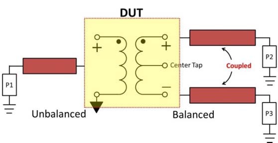
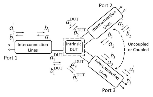
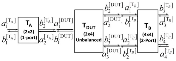
In the real modern electronic system, the interconnectors in the input and output terminals are usually multi-port, and there are inevitable coupling effects generated among the closed interconnection lines. As the coupled phenomenon for a multiport is so complicated that it requires a separate analysis for a detailed explanation, in this step, we only consider the most common case for a three-port network with two ports coupled, as illustrated in Fig. 2. In the three-port network with two ports coupled, the non-diagonal entries in the coefficient matrices
The proposed method has a derivation similar to the approach method in Section II, and the difference in the nondiagonal entries of the coefficient matrices in the conversion of
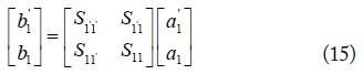
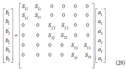
Herein, the derivation started with a three-port model, where port 2 and port 3 are coupled with each other. The characteristic of interconnection for port 1 is described as (15), which is the same as the uncoupled situation. Changes happened in (16), where the non-diagonal entries indicate the coupling effect but are not null, as in the uncoupled case.
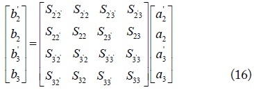
Each incident and reflected wave of the DUT is easily obtained by the equations constituted by the four rows of (16), and the relationship represented by the [
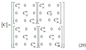
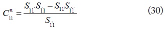
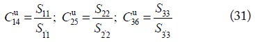
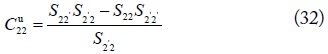
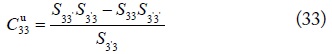
A matrix expression of the
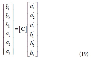
where the [
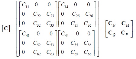
Each term of the new [
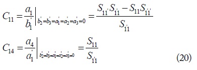
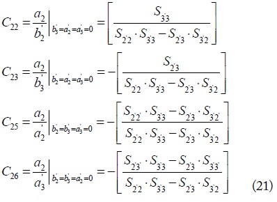
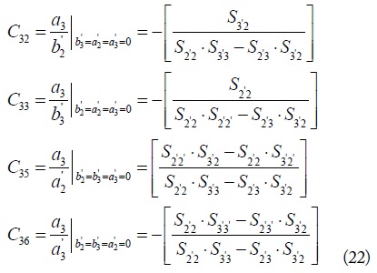
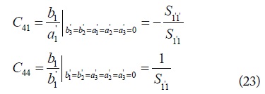
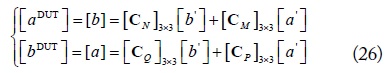
Thus, a new expression of (16) is achieved in (26) for deriving the final


Ultimately, the proposed de-embedding method for both uncoupled and coupled interconnection lines is demonstrated in detail. The merits of our method are easily observed in Table 1, with a comparison of existing de-embedding methods and ours.
[Table 1.] A performance comparison of the existing de-embedding methods and our proposed approach
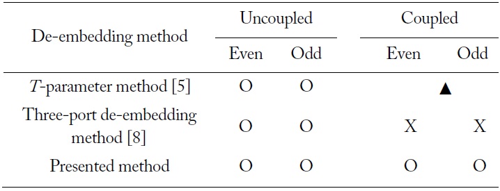
A performance comparison of the existing de-embedding methods and our proposed approach
In the uncoupled case, when the non-diagonal of the [

It is interesting to see that the introduction of coupling for just two lines makes the formula extremely complicated in the de-embedding derivation.
IV. CASE STUDY FOR COUPLED INTERCONNECTION LINES
The validation of the proposed method was performed based on the Agilent commercial circuit simulator—the Advanced Design System (ADS). In the circuit simulator, the microstrip line model is easily defined and the
The de-embedding method proposed for analyzing the characteristics of on-wafer metal–oxide–semiconductor field-effect transistor (MOSFETS) in [8] can no longer be effective for the coupled interconnection lines, as the non-diagonal elements in the
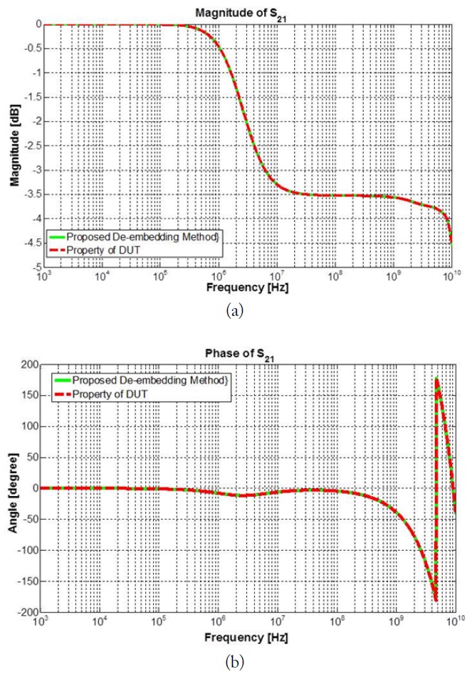
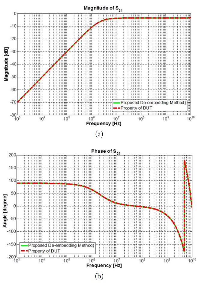
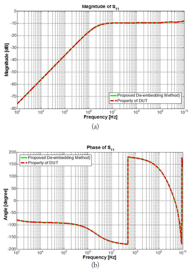
Although the result cannot be obtained by the method in [8], our proposed method worked well, and the extracted result matched the result from the simulation in a wide frequency range, as illustrated in Figs. 5–7. It validated the accuracy of our proposed de-embedding approach for coupled lines from a low frequency (1 kHz) to a high frequency (10 GHz). To shorten the calculating time, a code is made based on the mathematics language and is realized in MATLAB, which is a technical computing language used in engineering. The touchstone file constituting the property of the
This paper proposed a de-embedding method for uncoupled and coupled interconnection lines based on the conversion of the