검색 전체 메뉴
PDF
맨 위로
OA 학술지
Miniaturized Radio Frequency Choke Using Modified Stubs for High Isolation in MIMO Systems
  • 비영리 CC BY-NC
  • 비영리 CC BY-NC
ABSTRACT
Miniaturized Radio Frequency Choke Using Modified Stubs for High Isolation in MIMO Systems
KEYWORD
Isolation Technique , MIMO System , Radio Frequency Choke (RFC)
  • I. INTRODUCTION

    Recently, as wireless mobile communication techniques have grown rapidly, mobile devices have become light-weight, thin, and highly integrated. Because of these trends, mutual interference among the small components is getting worse. In multiple-input-multiple-output (MIMO) antenna systems, which share a common ground plane, antenna performances can be degraded. The problems include impedance of matching characteristics, return loss (S11), radiation patterns; also, undesired noise can occur by the electromagnetic coupling, which is brought on by the inflow of ground edge current. Therefore, the isolation techniques among the integrated small components are regarded as one of the mos important considerations. To prevent these drawbacks, several studies have been conducted with the goal of improving isolation. An inverted-Y-shaped stub structure [1], a parasitic element with a T-shape [2], and two parasitic monopole elements [3] have been used to enhance the isolation between multiple-antennas. These types of techniques can achieve high isolation between antenna elements.

    However, these structures are too big to implement in small devices. In [4, 5], mushroom-like electromagnetic band-gap (EBG) structures and defected ground-plane structures (DGS) are presented as isolation techniques. However, even though those modified ground structures are designed with high isolation characteristic, the negative effects, such as degradation of diversity gain, decreased efficiency, and impedance mismatch can accompany them, and they also have structurally large designs.

    In this paper, a miniaturized radio frequency choke (RFC) consisting of modified stubs in MIMO antenna configuration is proposed to prevent ground edge current. The proposed RFC is composed of a bent open stub and slit structure on the ground plane that provides LC resonance in the LTE 2300 band.

    The RFC using the slit structure is proposed for not only decreasing the size but also maintaining the antenna performances.

    II. DESIGN OF THE PROPOSED RFC

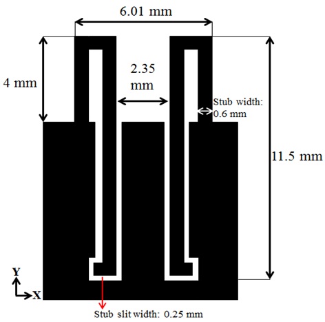
    The configuration of the RFC is shown in Fig. 1. The proposed RFC consists of two bent stubs that are implemented on the top of the ground plane and a single layer structure printed on FR-4 substrate (εr = 4.3, tan δ = 0.025) with a thickness of 0.6 mm. The isolation characteristic is based on the LC resonance by the structure of the RFC. The inductive and capacitive components can be changed by modifying the length of the stub and the gap between the stub and ground plane, respectively. The proposed RF choke is based on the microstrip filter theory. Therefore, the proposed structure acts as an LC band-stop filter.

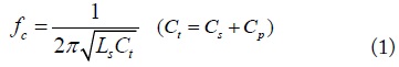
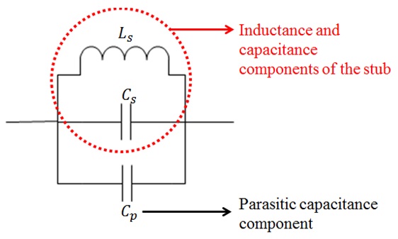
    The equivalent model for the proposed RFC is shown in Fig. 2. As previously mentioned, the proposed RF choke is based on the microstrip filter theory, and the bent stub has inductance and capacitance, which leads to the LC resonance characteristic. In the red circle, inductance and capacitance components, which vary according to the length of the stub, are represented, and the parasitic capacitance component (Cp), is a capacitor from the gap between the stub and the ground plane. The operating frequency of the RFC can be calculated with following equation.

    image

    The proposed RFC can be miniaturized by adjusting the gap-width, which provides additional capacitance in the RFC structure. As a result, the total electrical length of the stub (conventional λ/4 open stub at 2,350 MHz is 32 mm) is 14.3 mm (= 0.11 λ), which is shortened by around 40% as compared with conventional length of the open stub. Finally, the RFC has compact dimensions of 6.01 mm × 11.5 mm (0.047 λ × 0.09 λ).

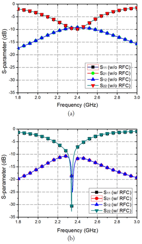
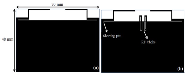
    The overall MIMO configuration (overall dimensions are 70 mm × 48 mm) is shown in Fig. 3. Fig. 3(a) is the configuration without the RFC and Fig. 3(b) is when the RFC is placed in the middle of two IFAs. Each IFA is designed to verify the isolation performance in LTE 2300 band (2,300– 2,400 MHz) and to have a return loss under -6 dB (VSWR < 3) in the whole frequency range, as will be shown in Fig. 4.
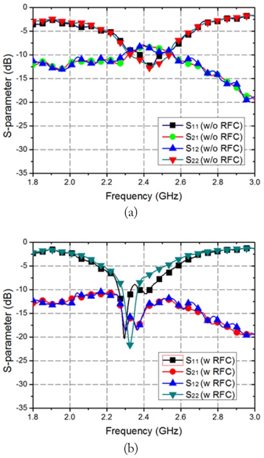
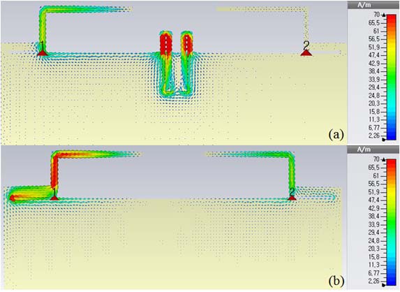
    The simulated S-parameter characteristics and current distribution with and without the RFC are shown in Figs. 4 and 5, respectively. Originally, the IFAs were designed at 2.35 GHz. However, because of the induced ground edge current as shown in Fig. 5(b), the operating frequency of return loss (S11) is slightly shifted to the higher band, which causes the degradation of the antenna performance. In Fig. 5(a), most of the ground edge current is induced in the RFC. As a result, the isolation characteristic is improved in the whole frequency range, as shown in Fig. 4(b).

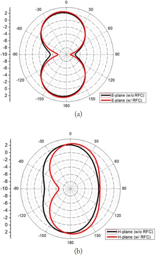
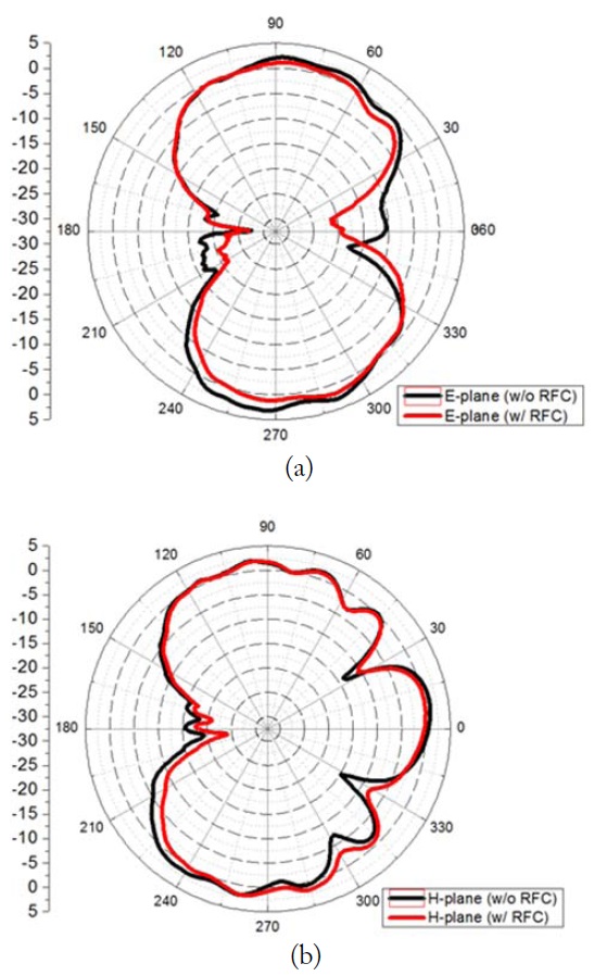
    Fig. 6(a) and (b) represent the simulated radiation patterns on E- and H-planes with and without the RFC. On each plane, irrespective of the presence of the RFC, the radiation pattern is almost the same especially in the maximum radiation direction.

    III. MEASUREMENT RESULT

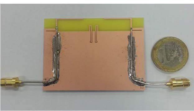
    The fabricated RFC, which is located in the MIMO antenna configuration, is shown in Fig. 7. The measured S-parameter characteristics with and without the RFC are represented in Fig. 8. As shown in Fig. 8(a), the transmission coefficients are relatively high. In other words, the ground edge current is induced to another antenna element, and it can degrade the antenna performance.

    On the other hand, the isolation performance can be improved by adding the proposed RFC. The transmission coefficient is under -15 dB in the whole LTE 2,300 band (2,300–2,400 MHz) without degradation of antenna performance.

    Fig. 9 depicts the measured radiation pattern on E- and H-planes. The measured radiation pattern is similar to the simulation result. The realized gain in the desired direction is 2.6 dBi.

    In a MIMO antenna system, the correlation between the signals received from two antennas is an important factor for evaluating diversity performance. The concept of envelope correlation coefficient (ECC) is using in this paper to evaluate the diversity capability in a multi-antenna system.

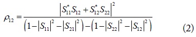
    The ECC should be computed using the 3D patterns from the full-sphere radiation patterns or directly in a representative scattering environment and can also be calculated with scattering parameters [6, 7]. The calculation of the ECC between the two antennas is given by following equation.

    image

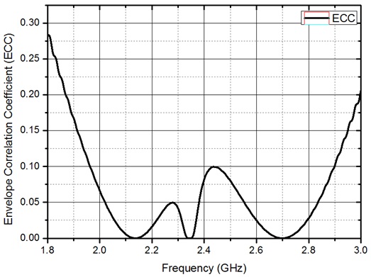
    In Fig. 10, the achieved ECC is under 0.08 in the LTE 2300 band. It allows for low ECC in the frequency range of 2,300–2,400 MHz. The diversity performance in MIMO antenna configuration can be improved by implementing the proposed RFC.

    IV. CONCLUSION

    In this paper, a miniaturized RFC using a modified stub has been proposed to improve isolation characteristics in MIMO antenna configuration. The proposed RFC consists of an open stub that is bent and a slit structure on the ground plane. The electrical length of the proposed RFC is shortened by around 40% (0.25 λ → 0.11 λ) as compared with conventional open stub. Thus, the proposed RFC has miniaturized dimensions of 6.01 mm × 11.5 mm. By implementing the proposed RFC into the MIMO antenna configuration, the antenna performances are maintained and isolation characteristics are improved in the whole LTE 2300 band (2,300–2,400 MHz). The high isolation performance is also evaluated by analyzing the ECC and S-parameter characteristics. The proposed RFC is expected to improve diversity performance so that it can be practically used in the MIMO system.

참고문헌
  • 1. Najam A. I., Duroc Y., Tedjni S. 2011 "UWB-MIMO antenna with novel stub structure," [Progress in Electromagnetics Research C] Vol.19 P.245-257 google cross ref
  • 2. Li Z., Du Z., Gong K. 2009 "A dual-slot diversity antenna with isolation enhancement using parasitic ele-ments for mobile handsets," [in Proceedings of Asia Pacific Microwave Conference (APMC)] P.1821-1824 google
  • 3. Toktas A., Akdagli A. 2014 "Wideband MIMO antenna with enhanced isolation for LTE, WiMAX and WLAN mobile handsets," [IEEE Electronics Letters] Vol.50 P.723-724 google cross ref
  • 4. Yang F., Rahmat-Samii Y. 2003 "Microstrip antennas integrated with electromagnetic band-gap (EBG) structures: a low mutual coupling design for array applications," [IEEE Transactions on Antennas and Propagation] Vol.51 P.2936-2946 google cross ref
  • 5. Ahn D., Park J. S., Kim C. S., Kim J., Quan Y., Itoh T. 2001 "A design of the low-pass filter using the novel microstrip defected ground structure," [IEEE Transactions on Microwave Theory and Technology] Vol.49 P.86-93 google cross ref
  • 6. Hallbjorner P. 2005 "The significance of radiation efficiencies when using S-parameters to calculate the received signal correlation from two antennas," [IEEE Antenna and Wireless Propagation Letters] Vol.4 P.97-99 google cross ref
  • 7. Blanch S., Romeu J., Corbella I. 2003 "Exact representtation of antenna system diversity performance from input parameter description," [Electronics Letter] Vol.39 P.705-707 google cross ref
OAK XML 통계
이미지 / 테이블
  • [ Fig. 1. ]  Configuration of the proposed radio frequency choke.
    Configuration of the proposed radio frequency choke.
  • [ ] 
  • [ Fig. 2. ]  Equivalent model of stub structure.
    Equivalent model of stub structure.
  • [ Fig. 3. ]  Overall MIMO configuration: (a) without the radio frequency choke and (b) with the radio frequency choke.
    Overall MIMO configuration: (a) without the radio frequency choke and (b) with the radio frequency choke.
  • [ Fig. 4. ]  Simulated S-parameter characteristics (a) without the radio frequency choke (RFC) and (b) with the RFC.
    Simulated S-parameter characteristics (a) without the radio frequency choke (RFC) and (b) with the RFC.
  • [ Fig. 5. ]  Simulated current distribution (a) with the radio frequency choke (RFC) and (b) without the RFC.
    Simulated current distribution (a) with the radio frequency choke (RFC) and (b) without the RFC.
  • [ Fig. 6. ]  Comparison of simulated radiation patterns with and without the radio frequency choke (RFC). (a) E-plane and (b) H-plane.
    Comparison of simulated radiation patterns with and without the radio frequency choke (RFC). (a) E-plane and (b) H-plane.
  • [ Fig. 7. ]  Configuration of the fabricated radio frequency choke (RFC) in MIMO antenna configuration.
    Configuration of the fabricated radio frequency choke (RFC) in MIMO antenna configuration.
  • [ Fig. 8. ]  Measured S-parameter characteristics (a) without the radio frequency choke (RFC) and (b) with the RFC.
    Measured S-parameter characteristics (a) without the radio frequency choke (RFC) and (b) with the RFC.
  • [ Fig. 9. ]  Comparison of measured radiation patterns with and without the radio frequency choke (RFC). (a) E-plane and (b) H-plane.
    Comparison of measured radiation patterns with and without the radio frequency choke (RFC). (a) E-plane and (b) H-plane.
  • [ ] 
  • [ Fig. 10. ]  Calculated envelope correlation coefficient (ECC).
    Calculated envelope correlation coefficient (ECC).
(우)06579 서울시 서초구 반포대로 201(반포동)
Tel. 02-537-6389 | Fax. 02-590-0571 | 문의 : oak2014@korea.kr
Copyright(c) National Library of Korea. All rights reserved.