Body-worn antenna research for body-centric communication has increased over the last decade. Ever smaller electronics have enabled a wide range of new applications where wireless communication can be implemented. Many of these new applications have been developed for medical devices, such as hearing instruments (HIs). There is considerable interest within the HI industry in obtaining Ear-to-Ear (E2E) communication between HIs. An E2E link improves the acoustic performance of HIs as well as the usability. Besides E2E communication there is an interest in communication with both on- and offbody accessories, for example smartphones, smart watches, or TVs. By the use of the license-free and worldwide industrial, scientific, and medical (ISM) band between 2.40 GHz and 2.48 GHz both E2E and accessory communication can be obtained. At the same time it will enable communication with electronics with Bluetooth. Antennas suitable for Behind-the-Ear (BTE) HIs have been presented in the literature with an E2E path gain of -52 dB [1]. BTE HIs are located behind the ear and are mass produced whereas In-the-Ear (ITE) HIs are placed in or right outside the ear canal and are custom-made to fit the user’s ear and ear canal. This makes it harder to achieve a high E2E path gain for ITE HIs. The ITE antennas that have been presented in the literature have not yielded E2E path gains significantly above -90 dB [2, 3]. In the following a novel ITE antenna, which is the first to make E2E communication feasible between ITE HIs is presented. The antenna was first presented briefly in [4]. This is an augmentation of the article presented in [5].
At 2.45 GHz, the human body is very lossy [6]. Therefore, the electromagnetic energy cannot propagate through the body. It has been shown that the electromagnetic energy propagates around the human body as creeping waves instead [7]. Models for the E2E propagation channel have been presented in [8, 9]. These models estimate the E2E path gain by the use of a number of elliptic paths around the head. For each of these paths, an estimate of the magnitude of the creeping wave launched in each path is made. The attenuation along each path is calculated by a closed-form expression. Finally, the contributions of each of the paths are added to give the path gain. In [9], the on-body gain is used to estimate the magnitude of the launched creeping waves. The on-body gain will be used to evaluate the radiation pattern of the antenna presented here. The phase of the electric field has been included in the on-body gain to account for the initial phase differences in the launched creeping waves. This means that the on-body gain is an untraditional gain that has both a magnitude and a phase, which can be expressed as:

where
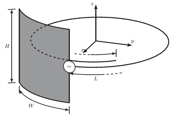
The antenna consists of a ground plane connected to a monopole with radius
[Table 1.] Optimized antenna design parameters

Optimized antenna design parameters
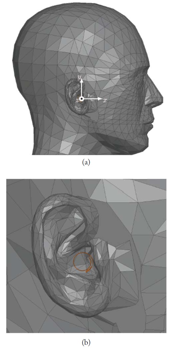
Simulations were done in ANSYS HFSS 2014. The specific anthropomorphic mannequin (SAM) fitted with realistic ears was used. The head and ears were given homogeneous electrical parameters of
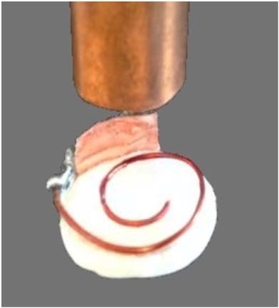
The prototype used for the measurements can be seen in Fig. 3. ROHACELL HF (
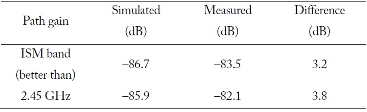
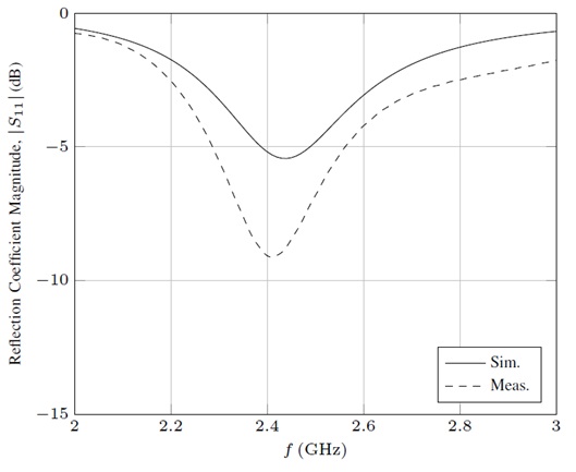
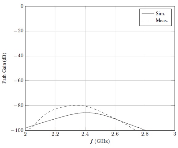
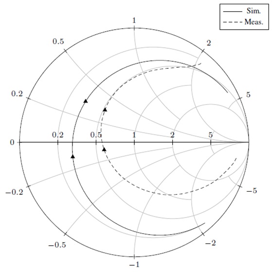
The simulated and measured E2E path gain is shown in Fig. 4. In the entire ISM band, the simulated and measured path gains are better than -86.7 dB and -83.5 dB, respectively. The measured and simulated E2E path gains in the ISM band and at 2.45 GHz are given in Table 2. It is noted that this is within the dynamic range of many standard Bluetooth ICs. Since the antenna is completely
[Table 2.] Measured and simulated Ear-to-Ear path gain

Measured and simulated Ear-to-Ear path gain
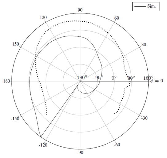
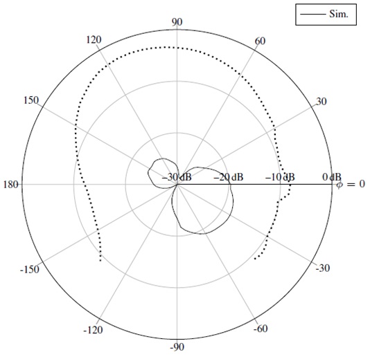
The magnitude and phase of the simulated on-body gain calculated from Eq. (1) can be seen in Figs. 7 and 8, respectively. From Fig. 7 it is seen that the radiation pattern has two lobes, which are in opposite directions. The radiation patterns for other ITE antennas found in [8, 12] exhibit the same characteristic, which might indicate that this is a general trend for ITE antennas and is caused by the ear. Furthermore, it is seen that the lobe in the forward direction has the highest gain. The BTE antennas presented in the literature have had their main lobe in the backward direction; see for example [9]. Therefore, contrary to BTE antennas, it is important to understand how the creeping wave propagates across the face. The previously mentioned E2E on-body path gain models in [8, 9], which model the head with elliptic curves, have been tested with antennas where the main path is behind the head. Since the face is not as well modeled with elliptic curves as the back of the head, it is suggested that these models be tested with the main path around the front of the head. The phase of the on-body gain seen in Fig. 8 has a spiral characteristic corresponding to the shape of the antenna. This is different from the phase pattern in [12] and indicates that the phase is not only determined by the presence of the ear. Furthermore, it is noted that the two lobes are out of phase.
A novel ITE antenna has been designed, simulated, prototyped, and measured. It is the first ITE antenna that is feasible to implement and yields a high enough path gain to be used with standard Bluetooth ICs. The measured and simulated E2E path gain at 2.45 GHz was –82.1 dB and –85.9 dB, respectively. The antenna was well matched in the entire ISM band. The on-body radiation pattern was presented and discussed. The radiation pattern showed two lobes. The main lobe was toward the front of the head and thus opposite to what has been observed for BTE antennas. Therefore, it is suggested that it is investigated whether the existing models of the E2E path gain can be improved. Furthermore, it was found that it is possible to modify the phase of the on-body gain for ITE antennas through the antenna design.