In this paper, in order to solve the problems of a narrow viewing angle and the flip effect in a three-dimensional (3D) integral imaging display, we propose an improved system by using an eye tracking method based on the Kinect sensor. In the proposed method, we introduce two types of calibration processes. First process is to perform the calibration between two cameras within Kinect sensor to collect specific 3D information. Second process is to use a space calibration for the coordinate conversion between the Kinect sensor and the coordinate system of the display panel. Our calibration processes can provide the improved performance of estimation for 3D position of the observer’s eyes and generate elemental images in real-time speed based on the estimated position. To show the usefulness of the proposed method, we implement an integral imaging display system using the eye tracking process based on our calibration processes and carry out the preliminary experiments by measuring the viewing angle and flipping effect for the reconstructed 3D images. The experimental results reveal that the proposed method extended the viewing angles and removed the flipping images compared with the conventional system.
Recently, integral imaging (InIm) has been considered one of the effective technologies for next-generation threedimensional (3D) displays [1-10]. In general, the pickup part of InIm is composed of a lenslet array and a twodimensional (2D) image sensor. Here, the optical rays coming from a 3D object are picked up by the lenslet array and recorded with the 2D image sensor as elemental images, which have their own perspective of the 3D object. On the other hand, the display part of InIm is a reverse of the pickup process. The elemental images are displayed in front of the lenslet array for the reconstruction of 3D images. InIm has several merits and can provide both horizontal and vertical parallaxes, color images, and quasi-continuous views to observers [1-4]. However, it also has the drawbacks of a low-resolution 3D image, a narrow viewing angle, and a small depth range. Many researchers have been working towards solving these problems [5-10]. Among them, as a solution to the abovementioned limitation of the viewing angle, the computer vision technology of eye tracking has been applied to the InIm display system [5]. Here, the researchers proposed a tracking InIm system with an infrared (IR) camera and IR light-emitting diodes, which can track the viewers’ exact positions. However, since the user has to wear headgear with IR diodes on his/her head to check his/her position, this system is not suitable for practical applications. In this paper, we propose an improved InIm system with an eye tracking method based on the Kinect sensor [11,12]. To do so, we need a tracking system to change the elemental images dynamically when the viewer’s position is changed. In the proposed method, we newly introduce a 3D space calibration process for obtaining a more exact 3D position of the observer’s eyes. The use of the eye tracking technology in InIm can provide a wider viewing angle for 3D image observations.
II. PROPOSED INIM DISPLAY SYSTEM WITH THE KINECT SENSOR
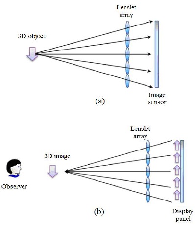
Fig. 1 shows the principle of the InIm method. An InIm system is composed of two processes: a pickup process and a display process, as shown in Fig. 1(a) and (b), respectively. In InIm, the lenslet array is used in both processes to capture 3D objects and reconstruct 3D images. In the pickup process, the light rays coming from 3D objects pass through the lenslet array and record a set of different perspective images by using an image sensor. These recorded images are referred to as elemental images (EIs). In the reconstruction process, a lenslet array similar to that in the pickup process is used. The 3D images are formed at the location where the image was picked up by backpropagating light rays of the EIs through the lenslet array.
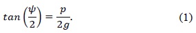
In general, the viewing angle

From Eq. (1), we can see that the viewing angle is dependent on the diameter of each lens and the gap between the lens array and the display panel. In general, the viewing angle is small because of the use of the lens array with a large f-number. For example, when p = 1 mm and g = 3 mm, the viewing angle becomes 18.925°.
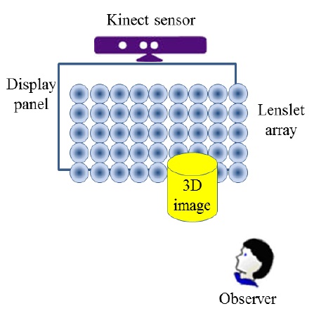
In this study, we want to improve the viewing angle by using the eye tracking technology based on the Kinect sensor. The structure of the proposed system is shown in Fig. 2. The Kinect sensor is placed on top of the display panel to detect the eye position of the observer. In this system, the proposed tracking method is as follows: for the given InIm system, firstly, we calibrate the 3D space to calculate the exact 3D location of the observer’s eyes. Secondly, we find 3D location of the observer’s eyes by using the tracking technology. Thirdly, we generate elemental images to display 3D images after considering the abovementioned eye location at a real-time speed.
>
B. 3D Space Calibration and the Coordinate Conversion Matrix
In general, a tracked object is oriented by the image’s coordinate system and displayed on the 2D coordinate display system. In the real world, however, the coordinate system is represented by the 3D space. Therefore, we need to calibrate the 3D space and perform a coordinate conversion between the image plane and the real 3D space. To calibrate between the image plane and the real 3D space, we need the position information of the observer and the target object. To solve this problem, we choose a 3D camera and use it as a tracking system.
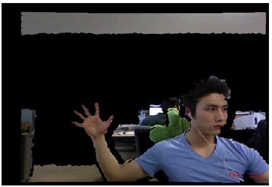
Various 3D cameras and different types of methods have been developed to obtain 3D information in a real 3D space [11-14]. One of the widely used sensors is Kinect from Microsoft, which is a pattern structured IR-light type sensor. This device can provide color and depth information simultaneously [11]. However, it faces a problem due to the physical separation between the color and the depth cameras. To overcome this problem, we reference its software development kit (SDK) from Microsoft and develop a simple solution. We can use references in the function ‘NuiImageGet-ColorPixelCoordinateFrameFromDepth PixelFrameAtResolution()’ [11]. Fig. 3 shows the processing result. Thus, we obtain the color and depth information, which is simultaneously mapped to one another in real time.
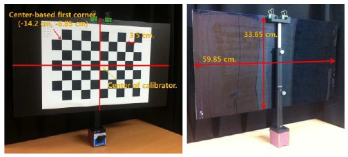
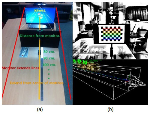
Then, we calibrate the 3D space. To do so, we use the calibrator to detect feature points and regular pattern influences in order to increase accuracy [14]. In the proposed system, we use the calibrator with the same size of the monitor display, as shown in Fig. 4. This figure shows the specific information of the calibrator. Next, we extend the monitor’s coordinate system by using the calibrator. We mount Kinect on top of the monitor and move in steps of 10 cm while capturing the calibrator. The initial distance is 80 cm due to the shortest possible capturing depth distance from the Kinect sensor. Further, the maximum distance is 150 cm. This distance is chosen because it is a reliable distance to accurately find the corner points. After capturing the points at each distance, we need a parallel listing of the corner points, i.e., the calibrator’s corner points (based on the image coordinates) and the calibrator’s physical corner positions (based on the world coordinates). Fig. 5 shows the corresponding processing result obtained by using OpenGL.
[Fig. 5.] (a) Extending the monitor’s coordinate system and (b) the corresponding processing result.
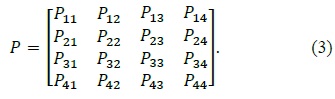
Using the listing of the corner points, we can calculate the least squares through projective transformation, for various 3D feature points. For the given
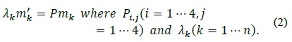
In this case, normally,

These equations can be simplified as follows:

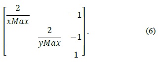
However, the difference between the columns of the data which is inside of the matrix has quite different magnitude. Thus, we need to normalize the values. When we find the least squares for various values, we prefer to normalize the values because doing so yields good results with respect to the least squares for the projective transformation matrix [16]. In our system, we set the center coordinates of the image as (0, 0). If we follow equation 6, the normalization result is from (−1.0, −1.0) to (1.0, 1.0). Further,

By following the normalization process, we can obtain a stable and correct projective transformation matrix
>
C. Estimating 3D Eye Position and Its Coordinate Conversion
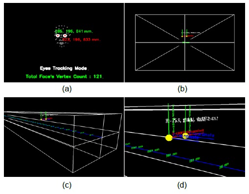
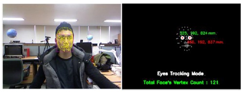
The Kinect SDK includes a face tracking library called ‘FaceTrackLib.’ It can detect a face with 121 vertices. Furthermore, it can provide the translate, rotate, and scale factors [11]. Among them, we just need the eye position. The Kinect SDK can detect the eye’s position with 18 vertices. In fact, the Kinect SDK can provide the coordinate position of only 2D vertices from the tracked face information. Therefore, we mapped the color and the depth information processes and consequently, obtained the eye’s correct depth distance from the Kinect sensor on the basis of the mapped depth information. Fig. 6 illustrates our process to detect the 3D position of the observer’s eye.
However, detected eye’s coordinate system is still oriented by Kinect’s own coordinate system. Therefore, we need to convert the coordinates system from the Kinect to the monitor. We already calculated the projective transformation matrix
>
D. Computational Generation of Elemental Integral Image for InIm Display
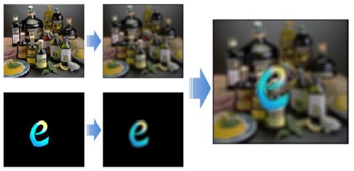
To display 3D images in the InIm system, we need elemental images. These images can be obtained by using either optical pickup or computational pickup. In this study, we use computational pickup, which is suitable for real-time generation of elemental images. For the sake of simplicity, we use two different images, namely a background image and a foreground image, as shown in Fig. 8. Each image is converted into the corresponding elemental images. Then, they are merged into the final elemental images and displayed through the InIm display system. Fig. 8 shows the concept of the generation process of elemental images, and the final generated elemental image for the InIm display is shown on the right side of Fig. 8.
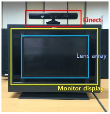
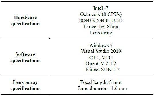
To show the usefulness of our system, we performed preliminary experiments. We used an ultra-high-definition (UHD) monitor as the display panel and placed the lens array in front of this panel. Kinect was placed at the top of the monitor. Fig. 9 shows an overview of our system environment. The specifications of this system are presented in Table 1.
[Table 1.] Specifications of the proposed implementation system

Specifications of the proposed implementation system
For the given system, we calibrated a 3D space by using the calibrator shown in Fig. 4. Then, we built a Kinect sensor to track the observer and find the 3D position of the observer’s eyes. Based on the 3D position of the tracked eyes, elemental images with two different image planes (background and foreground images) were generated and merged at a real-time speed.
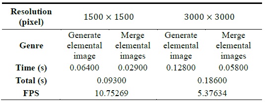
We checked the computational speed of the elemental image generation process for the real-time display system. Table 2 presents the measured results of the generation speed. The measurement process consisted of two steps. First, we measured the generation speed of each single elemental image, and then, we calculated the generation speed of merge two elemental images. We obtained generation speeds of 10 frames per second (FPS) for an image resolution size of 1500 × 1500 and 5 FPS for an image resolution size of 3000 × 3000.
[Table 2.] Evaluation of the generation speed of elemental images
Evaluation of the generation speed of elemental images
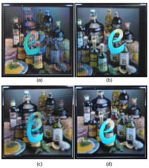
Next, we experimentally measured the viewing angle of the display system. Fig. 10 shows the results of a comparison of the conventional InIm display system and the proposed method. The observer is placed at a distance of 1 m from the display panel. When the observer moves to the left by 10 cm from the center position of the monitor with parallel, the conventional method causes the flip effect, as shown in Fig. 10(a). In contrast, the proposed method results in a more enhanced viewing angle and there is no flip effect at the displayed image, as shown in Fig. 10(b). Furthermore, there is no flip effect when we move in other directions in the case of the proposed method, as shown in Fig. 10(d). From the results shown in Fig. 10, we infer that the proposed system can improve the viewing angle compared with the conventional method.
The proposed system is a combination of an InIm display with a tracking system to overcome the InIm display’s limitations of the viewing angle and the flipped image. We conducted two rounds of calibrations to calibrate the 3D space. Further, we demonstrated the enhancement of the viewing angle of the InIm display for a dynamic user’s eye position by using a face tracking system based on Kinect. In the experimental result, we could see the 3D displayed image clearly in various positions. Further, the experimental results revealed that the implemented system effectively overcame the limitations of the conventional InIm system.