Implantable antennas provide better communication between the human body and the external environment. They promise better improvements in Patient Care Systems and quality of life, which has motivated their close examination by researchers. The research results have generated various innovations in the field of biomedical engineering such as glucose and blood pressure monitoring, pacemaker communication, insulin pumps, endoscopy, retinal prosthesis, etc. [1].
The proposed system may be a better replacement for patients who are under close observation for a period of time, so that they need not visit the hospital or stay there for several days. In this system, we install a Home Care Unit at the patient’s residence [2] and this unit, along with the accessory networking devices, regularly sends the required data regarding the patient’s condition to the medical examiner at the hospital [3]. The Medical implant devices are magnetically coupled to external equipment so that they can be in close proximity to the external monitoring device [4].
The medical implant devices require more time for data transfer, since they are operated with slow data rates. This is due to inductive communication the data rates have thus been improved by implementing Medical Implant Communication Services (MICS) [5].The antenna required for data transfer is designed in either air or the dielectric of the body. If designed in air, it performs well when air surrounds the implant, and if designed using the dielectric of the body, it performs best when the implant is inside the body cavity [6].
Therefore, while constructing an implantable antenna, it is critical to place the implant in the medium in which it operates. In this paper, an implantable antenna is proposed for industrial, scientific, and medical (ISM) applications. The proposed antenna is found to be compact in size and has a reasonable return loss of -10 dB to cover the ISM band, which is insensitive to the variation of the electrical properties of the human body. To reduce wave attenuation in a complex human environment, we choose the MICS band which operates electrically with very small antennas [7,8].The Microstrip and PIFA covered with dielectric materials with a frequency band of 402 MHz ~ 405 MHz have been proposed for implantable devices [9,10] &[11]. Only a few implantable antennas have been evaluated under the ISM band and the proposed system is mainly tested for ISM band applications. Since large implants are used to reduce the transmission range, we are forced to construct compact antennas for adequate use in the ISM band since human skin and body fluids are strong attenuatorsof signals. These issues continue with the use of the repeater units; the radiation characteristics are thus obtained while we simulate the tissue implant antenna using IE3D software.
This paper is organized as follows. In Section II, the geometrical details of the proposed antenna are discussed. Section III gives details on the operating principle of the implantable CPW fed antenna. This section also verifies through simulation and measured results that the proposed antenna is very suitable for ISM band medical applications. This is followed by a conclusion in Section IV.
2. GEOMETRICAL VIEW OF PROPOSED ANTENNA
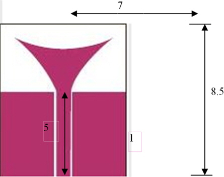
The CPW feeding transition structure used in this paper is investigated in detail and is shown in Fig. 1. For theoretical modeling, the proposed structure is divided into two symmetric parts. The symmetry of this device implies that the two fundamental quasi-TEM modes will be propagated in the out coming waveguide. The parts are described by homogeneous transmission lines for which the characteristic impedance (Z0), effective dielectric constant, and attenuation constant (dB/cm) are determined from the quasi static formulas based on the conformal mapping technique [13].
The basis of the antenna structure is a rectangular patch element with dimensions of 7 × 8.5 × 0.65 mm3 . The insertion of the appolian shaped patch results in the formation of an antenna fed by a CPW feeding structure. Based on the design dimensions shown in Fig. 1 and the prototype proposed, an implanted antenna was designed and tested.
Figure 1 shows the examined geometrical configuration of the implantable CPW fed appolian shaped antenna for ISM band biomedical applications. The antenna was constructed on a dielectric ceramic substrate with a thickness of 0.65 mm and dielectric constant εr of 9.8 and implanted into the muscle, skin, and fat with permittivity and conductivity [12].
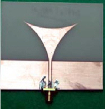
Experimental investigations are necessary in order to validate the numerical simulations for implantable CPW fed antennas. Since it is not possible to carry out measurements inside the human body, investigations are performed by measuring laboratory [CUSAT, Cochin]-fabricated prototypes [Fig. 3] inside one of the tissue-equivalent mediums (phantoms). Due to the unavailability of biocompatible materials in some laboratories, we purchased alumina ceramic material from Alibaba Manufacturers, China. The prototype fabrication of implantable antennas resolves all the classical difficulties of miniature antennas. The proposed antenna is fabricated with a biocompatible alumina ceramic substrate (εr=9.8, h=0.65 mm) as shown in Fig. 2.
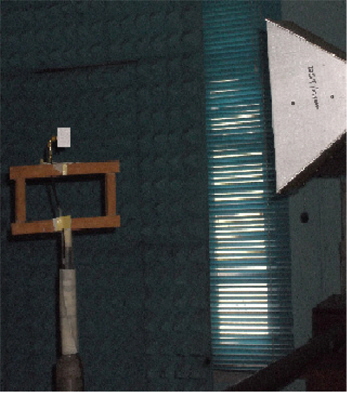
The proposed appolian shaped implantable antenna is connected to an Agilent Vector Network Analyzerinside the phantom, as shown in Fig. 4. S11 measurements were performed when the antenna was immersed in the human body phantom liquid.
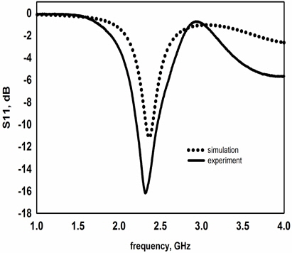
The simulations are performed using the IE3D simulator mentor graphics. Since the IE3D simulator is a 3D simulator, the finite size typically results in a shift of the resonance frequency to lower frequencies; thus, for the initial design in momentum, to cover the ISM Band, the antenna is designed to resonate at 2.45 GHz. Once fabricated and measured, this design ensures that our antenna will cover the complete requested bandwidth. The required -10 dB impedance bandwidth of the antenna is 320 MHz in the 2.45 GHz ISM band.
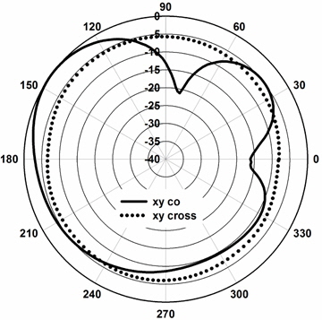
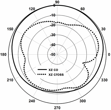
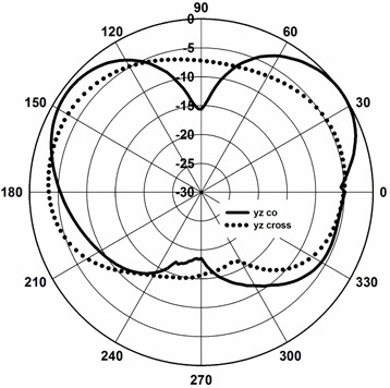
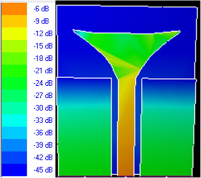
Figure 4 shows a comparison between the measured and simulated return loss of the antenna in planar state. The radiation characteristics of the antenna inside the liquid, simulating muscle, fat, skin,and tissue are determined in terms of radiation patterns and gain. The antenna is directed towards the surface of the gel (muscle, fat,and skin). Along the z-direction, the distance to the surface of the gel is set to the xy-plane, and the antenna is placed in the center of the surface of the human body phantom liquid.
The computed radiation patterns in the xy, xz and yz plane are measured and plotted in Fig. 5, Fig. 6, and Fig. 7, respectively. The 3D current distribution of the proposed antenna is shown in Fig. 8. The patterns are computed at 2.45 GHz, at a reference distance of 1m using an input power of 1.1W. The maximum gain is equal to-8dBi for θ=0 and φ=0 and the radiation efficiency is 0.32%. These values are comparable to other results in the literature [14]. The radiation efficiency is very low because the antenna is not in free space, but immersed into human tissue, simulated as a very lossy tissue medium.
In this paper, a novel implantable CPW fed appolian shaped antenna at 2.45 GHz ISM band for biomedical applications is presented with a compact size of (7 mm × 8.5 mm × 0.65 mm).In addition, solutions are suggested regarding the design, numerical simulations, and experimental investigations of the implantable CPW fed appolian shaped antenna for biomedical telemetry. The design of implantable antennas mainly emphasizes miniaturization and biocompatibility. The ISM band antennas that are currently being designed are limited to purposes for “coma patient treatment”, where the implantable medical device is only used when there is a need for information exchange. While a homogenous model is sufficient for antenna design, a more sensible model is needed to refine the antenna design and provide the best results. Due to the better dielectric constant of the alumina ceramic substrates, implantable antenna exhibit miniaturization, lower return loss, good VSWR, better impedance matching, and high gain compared to the conventional implanted antennas. Therefore, the proposed antenna is a suitable device for the ISM band frequency of 2.45 GHz in the field of Biomedical Engineering.