For several decades, underwater acoustic communications (UWAC) have been studied by many researchers. Recently UWAC has focused on various areas of interest including pollution monitoring of environmental systems, remote control in the marine oil industry, collecting deep-sea scientific data, and localization of submarines. In many application areas such as commercial or military fields, the requirement for real-time communication with submarines and deep-sea unmanned systems is increasing. The main restriction for using the underwater transmission medium is that the characteristics of the sea are very complicated and undergo continuous variation. The channel environment of UWAC in the shallow sea affects the propagation velocity of a signal according to the depth of the water, the distribution of water temperature, and the salt concentration.
There are many reasons such as multipath propagation, Doppler effects, noise, and attenuation as to decrease the communication performance in the underwater system. These elements caused from reflection, scattering, dispersion, and absorption of communication characteristics. These elements offers errors in performance and distance of communication. In particular, the propagation phenomena of multipath propagation appear because of the reflection of wave in the sea level and ocean floor. The Doppler effects varied very quickly for time, it is also affected by the season or the weather condition.
UWAC has much more restrictive conditions than terrestrial radio communication. It is difficult for UWAC to increase its communication capacity while the signal bandwidth is restricted because UWAC uses a very low carrier frequency in the ultrasonic band compared with terrestrial radio communication due to media characteristics. Nevertheless, underwater channels mostly use UWAC. To do this, a sound wave or acoustic communication is the most generally used mode and has been used widely.
Direct-sequence code division multiple access (DS-CDMA) [1, 2], orthogonal frequency-division multiplexing (OFDM) [1, 3-5], and multi-input multi-output (MIMO) [1, 6], modulation and error correction [7], and others [8-11] techniques that can transmit high-speed data are mostly available in UWAC. However, none of these methods can guarantee good communication performance underwater. Therefore, we need to find the best technique for UWAC in the underwater environment.
In this paper, we propose a novel method for underwater acoustically wireless transmission of data with high transmission rate. Our method uses DS-CDMA based on direct-sequence spread spectrum (DSSS). The method is physical layer and a multiple-access technique (i.e., the code division multiple channel access technique) to divide the channel into subchannels, and transmits data through these subchannels. The codes used are pseudo-random noise (PN) sequences. In a spread-spectrum technique, a signal (electrical, electromagnetic, or acoustic) generated in a particular bandwidth is deliberately spread in the frequency domain, resulting in a signal with a wider bandwidth. In this paper, we determine whether we can apply the DS-CDMA technique to an underwater system using MATLAB. As a result of our review, we recognize that DS-CDMA technique can be applied to an underwater system.
Because there is a single carrier frequency in the underwater system, we cannot use the frequency division multiple access (FDMA) channel access technique. In addition, we cannot apply the frequency-hopping spread spectrum (FHSS) technique to increase the bandwidth.
There are many multiple-channel access techniques, including time division multiple access (TDMA), FDMA, and CDMA. There are also some techniques that spread the spectrum of the transmitted signal in the frequency domain. These techniques include DSSS, FHSS, chirp spread spectrum (CSS), and timehopping spread spectrum (THSS).
In this paper, we consider DS-CDMA, which is a multiple-channel scheme based on DSSS that spreads the signal from different users with different codes in the underwater system.
DS-CDMA has various features and benefits. First, DS-CDMA is robust to frequency-selective fading. Second, DS-CDMA compensates for the effect of a multipath propagation at the receiver by exploiting rake filters, which can collect the transmitted energy spread over multiple rays. Third, DS-CDMA also allows receivers to distinguish among signals simultaneously transmitted by multiple devices. Because of these reasons, CDMA increases the number of to reuse channel and decrease the number of the packet retransmission. Therefore CDMA results in decreased energy consumption and increased network throughputs. Finally, DS-CDMA have an excellent security, noise/jamming immunity.
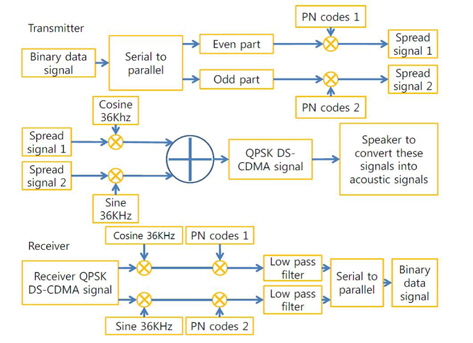
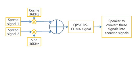
We considered that we had to transmit some data (text message, image, or video) in the underwater environment wirelessly and acoustically. We propose a novel method for underwater acoustically wireless transmission of data with a high transmission rate. Figure 1 shows the proposed block diagram for DS-CDMA based on DSSS in the underwater system.
In order to implement DS-CDMA based on DSSS in the underwater system, we need to accomplish three steps for the transmitter: quadrature phase shift keying (QPSK), a PN sequence, and an m-sequence. In addition, the receiver requires four steps: QPSK, a PN sequence, an m-sequence, and reverse filtering for the processing of the transmitter.
2.1.1 QPSK
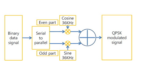
To build the QPSK modulated signal, we have to send the binary data signal as an input. In this paper we apply d(t), which is input binary data divided into two bipolar non-return-to-zero (NRZ) signals, to the serial-to-parallel converter. One part of the binary data at the serial-to-parallel converter is the even part, and another binary data is the odd part. These are called in-phase bit streams I(t) and quadrature-bit streams Q(t), for channels I and Q, respectively. Figure 2 shows the QPSK processing.
To make the two bipolar NRZ signals, we use Eqs. (1) and (2) for I(t) and Q(t), respectively.


where
Because we have determined that the sensitivities of our pinger (transmitter) and hydrophone (receiver) have a maximum 36-kHz frequency, we apply 36 kHz as a carrier frequency.
Eqs. (1) and (2) are the basis functions of two bipolar NRZ signals. These basis functions must have orthogonal characteristics. To determine the orthogonal basis signal between Eqs. (1) and (2), we consider the case of orthogonal basis signals that are shifted 45° from the original signal of Eqs. (1) and (2). We can describe the transformed orthogonal-basis signals using the following equations, respectively:


2.1.2 PN sequence
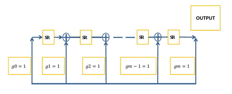
The next step is a synthesis of the PN sequence. We synthesize the PN sequence in the even part and odd part. The PN sequence can be realized by two types of Fibonacci and Galois. Figure 3 shows the block diagram of the synthesis process for the PN sequence.
In the PN sequence, Ci(t) and Cq(t) are needed for both channels. These can often be generated separately using two independent sequence generators. The product of the PN sequence and data signal, which is the output of the multiplier, is the baseband direct sequence spread signal.
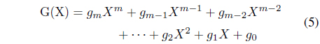
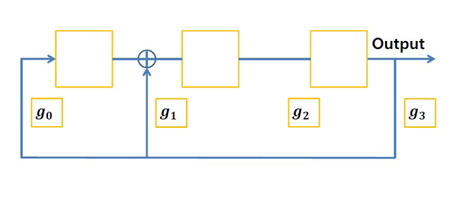
For the PN sequence we use two modulo which are linear feedback shift register (LSFR) and generalized generator polynomials. An LFSR is a shift register whose input bit is a linear function of its previous state. Generalized generator polynomial can be represented by Eq. (5).

For example, G(X) =
The constant 1 in the generator polynomial represents the input connection of the shift register,
2.1.3 m-sequence
Properties of m-sequences include an m-bit register that produces an m-sequence of period N = 2m - 1, and an m-sequence that contains exactly 2(m - 1) ones and 2(m -1 ) - 1 zeros. The modulo-2 sum of an m-sequence and another phase (i.e., time-delayed version) of the same sequence yields yet a third phase of the sequence.
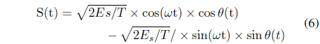
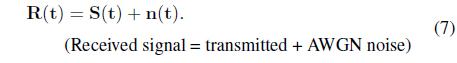
Therefore, we obtain the following equation for S(t):

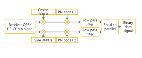
Figure 6 shows block diagram of demodulation processing in the receiver.
The receiver requires the demodulation process. Figure 6 shows the demodulation processing in the receiver.
The received signal is applied to the local multipliers, which are supplied with the locally generated coherent carriers. Subsequent to coherent down-conversion, the signal in each channel is dispread by correlating with the corresponding spreading waveforms. This results in two quadrature terms, Zi and Zq. The two bit streams are then multiplexed to obtain the final output bit stream using a generalized from serial-to-parallel converter, which incorporates a decision block as well.
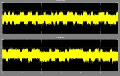
In this paper, Eq. (7) determines the received signal that is degraded by the noise. We can use white and Gaussian noise. We chose additive white Gaussian noise (AWGN) with a zero mean and two-sided power spectral density N0/2 with Ts, symbol time period.
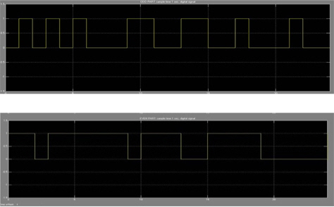
We performs a computer simulation for the modulation and demodulation of DS-CDMA with DSSS from Eq. (1) through (7) by using MATLAB. Figure 7 shows the converted into digital by sampling time with 1 seconds.
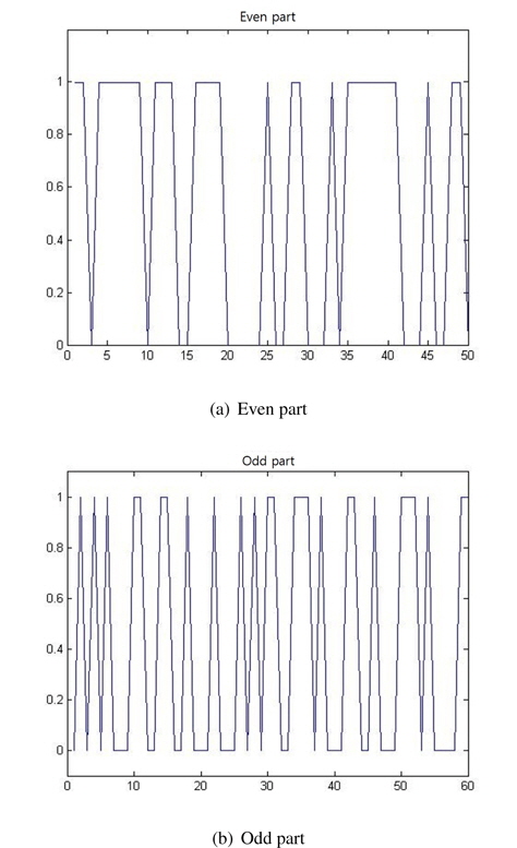
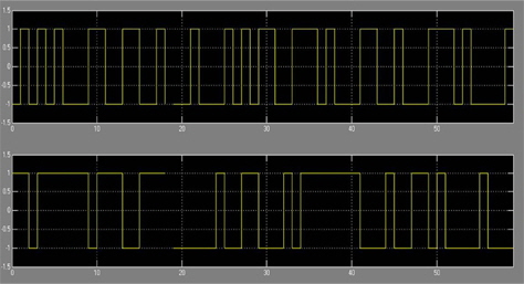
Figure 8 show the even and odd parts of the signal, respectively.
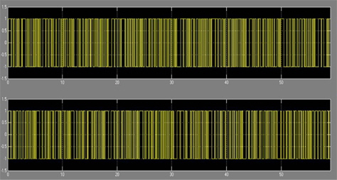
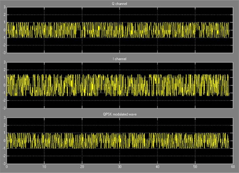
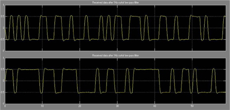
Figure 9 shows the signal after it is digitally converted into bipolar data. Figure 10 shows the PN sequence signal, which is the product of data with PN sequences I and Q from Eqs. (3) and (4), respectively. Figure 11 shows the modulated signal with the PN sequence for the Q-, I-, and QPSK-modulated signal, respectively. Figure 12 shows the recovered PN sequence signal in the receiver. Figure 13 shows the recovered signal in the receiver. Figures 7 and 13, we can compare transmitter signals and receiver signals. We recognize that the transmitter signals and recovered signals are the same. Hence, we know that DS-CDMA based on the DSSS technique can be applied to underwater communication systems.
This paper proposed a novel DS-CDMA based on DSSS in the underwater system. We determined whether we could apply the DS-CDMA technique in the underwater system by using MATLAB. As a result, we recognized that the DS-CDMA technique can be applied in the underwater system. We did not consider underwater conditions such as attenuation, noise, multipath propagation, or Doppler effects. However, we know that the DS-CDMA communication technique can be applied effectively in the underwater system. We compared DS-CDMA with other communication methods such as OFDM and MIMO. In the future, we need to study the application of our propose method to a real underwater communication environment that includes attenuation, noise, multipath propagation, and Doppler effects.