To improve the control performance of the IPMSM, a novel nonlinear disturbance observer is proposed by using the T-S fuzzy model. A T-S fuzzy model is the combination of local linear models considered at each operating point. Usually the inverse model is easy to obtain in linear systems but not in nonlinear systems. To design a nonlinear disturbance observer, a nonlinear inverse model is obtained based on nonlinear inverse model which is the fuzzy combination of the local linear inverse models. The proposed DOB is used with a PDC controller which is one of the T-S fuzzy controller, and its performance improvement is shown from the simulation results.
본 논문에서는 부하외란이 존재하는 경우에 T-S 퍼지모델을 이용한 비선형 외란 관측기를 제안함으로써 IPMSM(Interior Permanent Magnet Motor)의 제어성능 향상을 도모하였다. T-S퍼지모델은 국부선형모델들의 퍼지 결합으로 비선형계통을 T-S퍼지모델을 구한 다음, 각 국부선형모델의 역함수에 대한 T-S퍼지모델을 구함으로써 비선형 역함수를 구하는 방법을 제안하였다. 역함수를 이용한 외란관측기의 구성은 선형계통에서와는 달리 비선형 계통에서는 용이하지 않으나 T-S퍼지 모델을 사용함으로써 이 문제를 해결한 것이다. 제안된 비선형 외란관측기는 T-S퍼지제어기의 대표 격인 PDC 제어기와 함께 사용되었고 시뮬레이션을 통해서 그 유용성을 입증하였다.
Permanent magnet synchronous motors(PMSM) are widely used in various applications, such as electric vehicles and spindle motors under the field oriented control technique, with many advantages such as maintenance-free operation, high controllability, robustness against the environment, high efficiency and high power factor operation. There are Surface PMSM(SPMSM) and Interior PMSM(IPMSM)[1].
A SPMSM can be considered as a linear system with the zero d-axis current. However in the case of IPMSM, to obtain the maximum torque per ampere (MTPA)[2], its d-axis current must be controlled as nonzero reference, and this makes it difficult to control[3-6]. With the nonzero d-axis current, the dynamic of IPMSM is nonlinear and nonlinear control methods are required.
One of the effective nonlinear control method is T-S fuzzy control [7-11]. And to improve the robustness by eliminating the effect of disturbances, the use of disturbance observer(DOB) is desirable. The DOB based on the inverse model of the controlled plant have many research results and applications [12-15,18,19]. Usually, this kind of DOBs are designed for linear systems since the inverse models are obtained easily from transfer functions[20]. In nonlinear systems, the inverse system can be obtained under the very limited condition.
In this paper, for the robust control of IPMSM, a novel DOB is proposed based on the T-S fuzzy model, which is the convex combination of local linear models in the state space [11]. An inverse system of IPMSM is obtained as a convex combination of the local linear inverse systems[16,20]. The existence condition of an inverse system in the state space is to have a input direct through matrix D, however most systems including IPMSM have no such a matrix. To overcome this difficulty, a filter, which has a derivative and a low pass filter, is proposed in this paper[19]. A basic T-S fuzzy PDC controller is used with nonlinear DOB and simulation results shows the disturbance decoupling using the proposed DOB[13,17].
Ⅱ. BACKGROUND OF INTERIOR PERMANENT MAGNET SYNCHRONOUS MOTORS
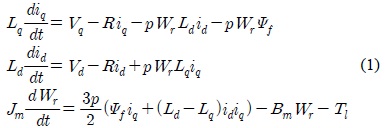
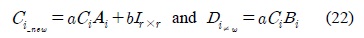
The following IPMSM model is considered.

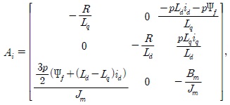
where Vd and Vq are d-q axis stator voltages, id and iq are d-q axis stator currents, Ld and Lq are d-q axis stator inductances, R is a stator resistance, Ψf is the rotor magnetic flux, T1 is a load torques, Jm is the moment of inertia, Bm is friction coefficient, and p is the number of poles.
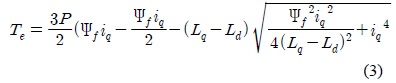
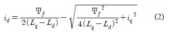
The MTPA can be achieved by differentiating Eq.(1) with respect to q-axis current iq and setting the resulting equation to zero, which gives in [6]:
Substituting Eq.(2) into Eq.(1), one can get a nonlinear relationship between iq and Te as:

In real time, the implementation of the drive system becomes potentially undefined and computationally burdensome with expressions Eq.(2) and Eq.(3).
To address this, the d-axis and q-axis currents are obtained by expanding the square root term of Eq.(2) via a Taylor series expansion about zero.
Ⅲ. TAKAGI-SUGENO FUZZY CONTROLLER FOR IPMSM
The design procedure described in this paper begins with the so-called Takagi-Sugeno fuzzy model, in which local linear models of a nonlinear system are combined by fuzzy IF-THEN rules [7].
The i-th rules of the T-S fuzzy models are of the following form.
Model rule i:
IF
THEN
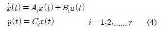
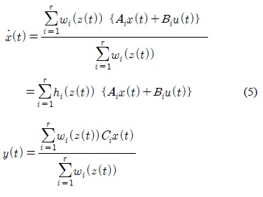
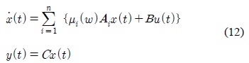
where Mij is the fuzzy set and r is the number of rules; x(t)∈Rn is the state vector, u(t)∈Rm is the input vector, y(t)∈Rq is the output vector, Ai ∈Rnxn, Bi ∈ Rnxm, and Ci ∈Rqxn are the parameters of local linear models, z1(t), … , zp(t). are known premise variables that may be functions of the state variables. We will use z(t) to denote the vector containing all the individual elements z1(t), … , zp(t). It is assumed in this paper that the premise variables are not functions of the input variables u(t). This assumption is needed to avoid a complicated defuzzification process of fuzzy controllers.
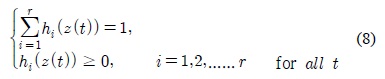
Given a pair of (x(t),u(t)), the final T-S fuzzy model is inferred as follows:

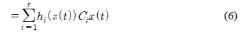
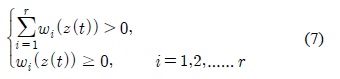
for all t. The term Mij(zj(t)) is the grade of membership of zj(t) in Mij. Since

We have

The stability of T-S fuzzy controller is determined based on the Lyapunov stability which can be applicable for a regulator problem.
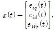
To change the tracking problem into a regulator problem, an error model is derived as follows. The reference input is determined from the following steady state equation:
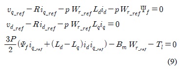
Note that variable id and iq are still shown in Eq.(1) and they are also included in the reference voltages.
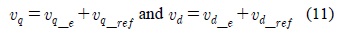
With the reference input currents, the d-axis and q-axis voltages of error model are determined as: By substituting the above Eq.(9) into Eq.(1) the error model is obtained as:
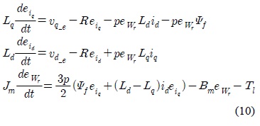
where
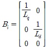
The above dynamics have simple nonlinear terms but difficult to be used for the design of DOB without T-S fuzzy approximation. For some constant values of iq(t), id(t), the system can be linear. If iq(t), id(t) are chosen as the premise variables, the following T-S fuzzy model of IPMSM is obtained:

where


Note that the parameter C can be determined as the desired value since the all states of IPMSM are usually measurable for the field oriented control.
Various type of T-S fuzzy controller can be used with the proposed DOB, however, in this paper, the most basic T-S fuzzy PDC controller, which does not consider any robustness, is used to show the disturbance decoupling of the proposed DOB.
A PDC controller has the following form:
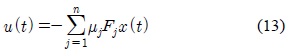
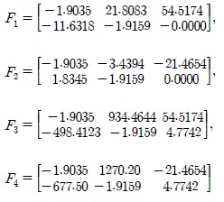
where Fj are calculated from the LMI.
The known load disturbances can be considered in the reference input, however unknown disturbance must considered by using disturbance observer. In the next section, a novel nonlinear DOB based on T-S fuzzy inverse system is proposed.
Ⅳ. T-S FUZZY DISTURBANCE OBSERVER FOR IPMSM
In this chapter, an inverse nonlinear system is derived and used for the design of a nonlinear DOB. The inverse systems have been studied by using transfer functions only for linear systems but seldom for the nonlinear systems[14,17].
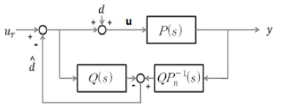
The following figure shows the basic concept of DOB in linear system using the transfer function.
In the Fig. 1, ur is the input of controller, u is the input after compensation, d is the unknown external disturbance, P(s) is the original plant, Pn-1 (s) is the useful inverse system of it.
The inverse system is obtained very easily from the transfer function and the problem is solved using the low pass filter under the condition of low frequency input and disturbances. However this approach is impossible in nonlinear systems. so, the following inverse T-S fuzzy model in the state space is proposed in this paper.
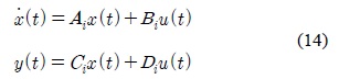
The i-th local linear system is described in the state space as follows:
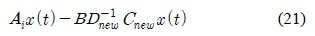
Under the assumption of existence of nonsingular D, its inverse system is obtained as follows:
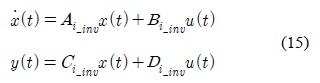
where and
For the above local inverse systems, a T-S fuzzy inverse exists if B=Bi, C=Ci and D=Di. In IPMSM, Bi and Ci are constant but D does not exist, then the inverse systems cannot be derived.
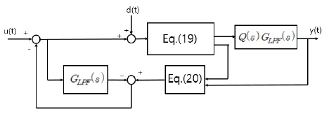
In this paper, to make an inverse system available, a special filter is proposed for the output.

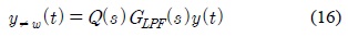
where Q(s) is the polynomial function of s and its output has the D matrix, and GLPF(s) is a low pass filter.
Suppose inputs and disturbances are low frequency signals and their outputs are not depend on the low-pass filter and the filtered output is considered as follows.
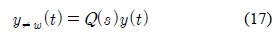
The role of Q(s) is to make
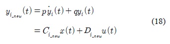
In this paper, Q(s) is given as (ps+q) for the IPMSM and its usage is explained as follows: for the inputs and disturbances which are not high frequencies, the low pass filter can be neglected and the yi-new(t) can be described as follows:

where The filter must be designed to give nonsingular Di-new.
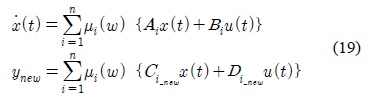
Through the convex combination, the overall T-S fuzzy model is obtained as follows:

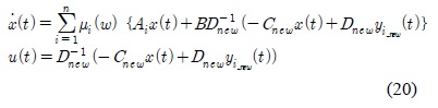
As a result, the inverse system of the IPMSM can be derived as follows:

Now the inverse system is the convex combination of local linear inverse systems and the overall stability is guaranteed by the stability of each local inverse system.
The stability of i-th local inverse system is described as a Hurwitz matrix as follows:
Note that the IPMSM has simple T-S fuzzy model and its inverse system easy to obtain, however, without T-S fuzzy model this kind approach is impossible.

Combining the DOB system with error system we built, we can get the overall system as a nonlinear DOB using T-S fuzzy model for IPMSM.
In next chapter, we will introduce a simulation to illustrate the performance of DOB applied to IPMSM.
In the previous chapters, we mainly proposed a T-S fuzzy control method with the disturbance observer (DOB) based on the inverse system for IPMSM. Simulation results for IPMSM will be shown with the proposed method.
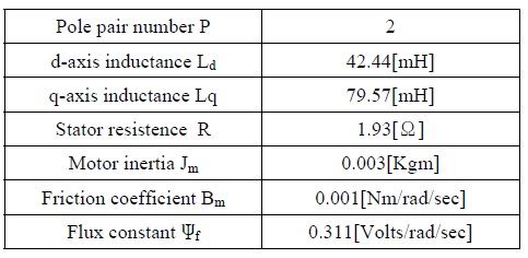
The parameters of the IPMSM, used in the simulation, are given in the following table.

IPMSM의 파라미터
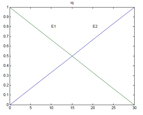
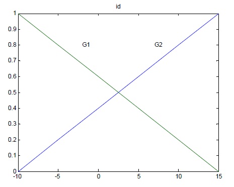
The membership functions are described in the following figures:
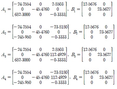
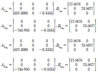
The parameters of the local linear models:

The PDC controller gains F:

The parameters of the inverse system models:
Two cases will be considered. The first one is control plant without DOB, and The second is with DOB. Through the comparation between the above two cases, the performance of DOB can be checked apparently.
The simulation results of the first are shown in the following figure.
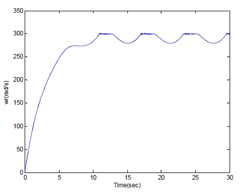
In the speed control, the reference speed is wr-ref = 300rad/sec and some sinusoidal signals will be applied on the plant as the unmeasured disturbance. Due to the disturbance, the output w fluctuates at 280 rad/sec and can not achieve the desired tracking performance.
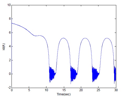
With the reference speed wr-ref = 300 rad/sec and some sinusoidal disturbance. As the d-axis current id in Fig. 5 shows, we can tell that disturbance will have a bad effect on id, and id could not tend to the desired steady state value.
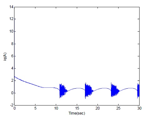
With the reference speed wr-ref = 300 rad/sec and some sinusoidal disturbance, the q-axis current iq behaves as the above figure. In the Fig. 7, iq fluctuates periodicly with the period of sinusoidal disturbance.
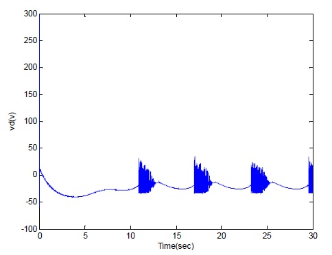
With the reference speed wr-ref = 300 rad/sec and some sinusoidal disturbance, the d-axis voltage vd is changed from 300V to 0V and at 11s the response fluctuates because of the disturbance.
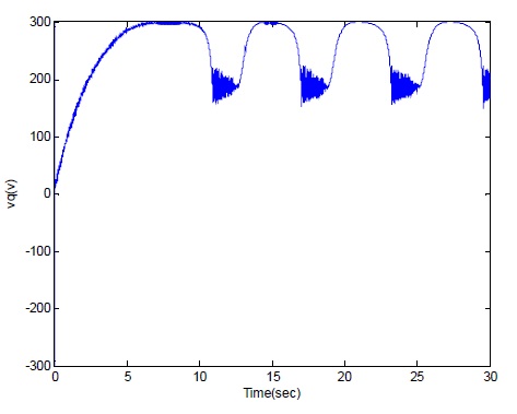
With the reference speed wr-ref = 300 rad/sec and some sinusoidal disturbance, the q-axis current vq is changed from 0V to 200V, but at 11s the waveform fluctuates periodicly with the disturbance.
From the above simulation results, without the DOB, the plant can not have a good performance to against the disturbance and shows the deteriorated stability and control performances.
The simulation results of the case 2 are shown in the following figure.
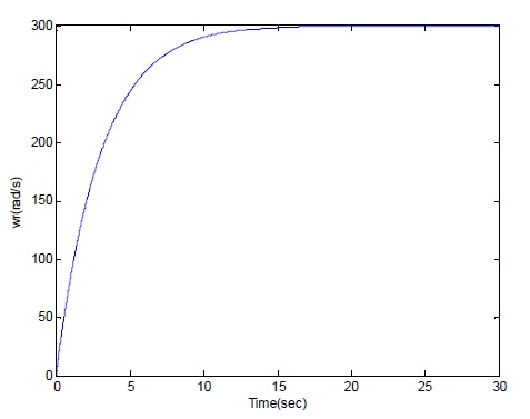
In order to make a comparation, here we still set the reference speed wr-ref = 300 rad/sec and the same desired sinusoidal signals. We can see even there exists a disturbance, after applying a DOB to the system, the system can realize the tracking performance, the value of w will tend to be steady to 300 rad/sec without any fluctuation as simulation time goes.
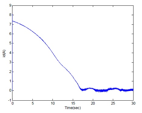
With the reference speed wr-ref = 300 rad/sec and some sinusoidal disturbance, the d-axis current id is as the above Fig. 11. We can tell that id tends to be the desired value.
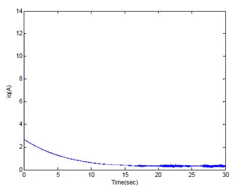
With the reference speed wr-ref = 300 rad/sec and some sinusoidal disturbance, the q-axis current iq tends to be desired value.
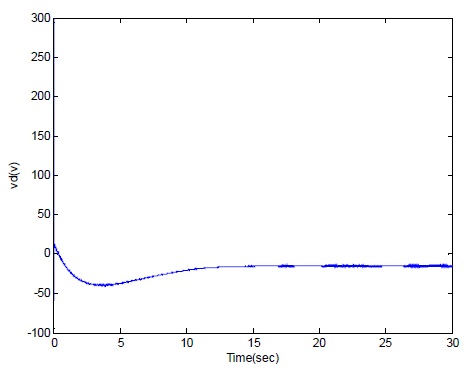
With the reference speed wr-ref = 300 rad/sec and some sinusoidal disturbance, even there still exists disturbance, after we build a DOB, it can make a compensation to deteriorate the negative effect of disturbance. And the waveform will range from 300 to 0 and finally tend to be a steady state.
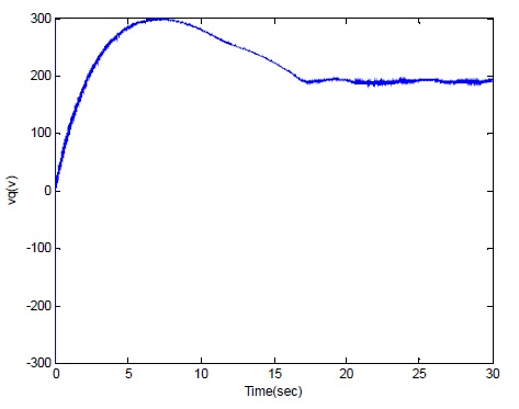
With the reference speed wr-ref = 300 rad/sec and sinusoidal disturbance, the q-axis voltage vq tends to be steady at 200V shown as the above Fig. 14.
Through the comparisons, the effectiveness of the proposed DOB is shown clearly.
The T-S fuzzy inverse model of IPMSM is derived by using the T-S fuzzy model, which is the convex combination of local linear inverse system in the state space. Using the inverse model, the nonlinear DOB is proposed and used with the PDC controller. The effectiveness of the proposed DOB has been shown through the computer simulation comparing the IPMSM system with DOB to the one without DOB.