Given the popularity of wireless communications, various industry standards have undergone significant development, including the Bluetooth, WLAN, GSM, GPS, UMTS, and CDMA. Of these wireless communication systems, the WLAN system, designed to serve as the backbone of shortrange wireless communication systems supporting the IEEE 802.11b/a/g (2.4–2.484 GHz, 5.1–5.35 GHz, and 5.725– 5.825 GHz) standards, has been developed for use on mobile phones and other handheld devices. Today, WLAN technology is one of the most successful and fastestgrowing wireless communication technologies in the world.
On the other hand, the Worldwide Interoperability of Microwave Access (WiMAX) technology has recently been adapted for mobile broadband wireless Internet supporting the IEEE 802.16e (2.5–2.69 GHz, 3.3–3.7 GHz, and 5.25– 5.85 GHz) standards. WiMAX technology can reach a theoretical 30-mile coverage radius and achieve a data rate of up to 75 Mbps, or throughput closer to the 1.5-Mbps performance of typical broadband services. WiMAX has been deployed to provide mobile broadband Internet services with large coverage areas in many countries [1, 2]. Thus, for short- and long-range applications in modern wireless communication systems, we need multiband and broadband antennas that simultaneously meet the WLAN and WiMAX standards.
Coplanar waveguide (CPW)-fed antennas for wireless communications have been discussed by many authors for a wideband or dual bands because of their many attractive features, such as bandwidth, a simple single metallic layer, and easy integration with active devices or MMICs. Thus, to develop multiband and wideband WLAN/WiMAX antennas, researchers have studied CPW-fed monopole antennas for WLAN/WiMAX band operations [3-19]. In particular, studies on the circular-ring monopole antenna have been conducted [20-23]. The CPW-fed dual-ring loop antenna for dual-band operation [20], the CPW-fed ring monopole UWB antenna with a band notch [21], the CPWfed circular-ring monopole with an inverted T-strip line for dual-band operation [22], and the circular-ring monopole with a half circular ring and ground slot for triple-band operations [23] have been reported. However, a CPW-fed half circular-ring monopole for triple-band operations has not been studied.
In this paper, a novel compact CPW-fed planar monopole antenna designed for triple-band operations is proposed for WLAN and WiMAX applications. The proposed antenna consists of two half circular rings and a microstrip feed line. By appropriately selecting the dimensions of the proposed antenna, a good triple-band impedance bandwidth and radiation characteristics suitable for WLAN/WiMAX communication systems can be obtained. Details of the proposed antenna design, simulated results, and measured results are presented and discussed below.
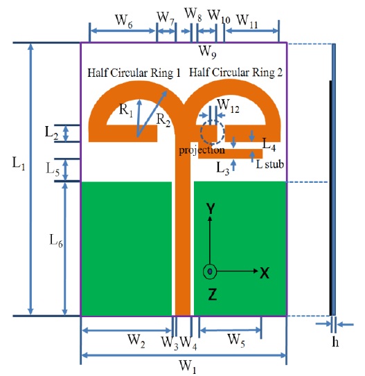
The schematic configuration of the proposed design of the WLAN/WiMAX-printed monopole antenna is shown in Fig. 1. The proposed antenna is based on two half circularring planar monopole designs. The total sizes of the substrate and the ground plane of the proposed antenna are 22.0 mm × 30.0 mm (W1 × L1) and 22.0 mm × 13.0 mm (W1 × L6), respectively. A 50-Ω CPW transmission line that consists of a single strip width of 2.0 mm and a gap distance of 0.7 mm between the single strip and the coplanar ground plane is used for feeding the antenna. With this design, the antenna is printed on a 1.0-mm-thick FR4 substrate with a relative permittivity of 4.4, is fabricated with the use of a conventional FR4 material that is often used for making printed circuit boards, and is easy to manufacture.
The proposed antenna has two modified half circular rings with a uniform width (L2 = W4 = 2.0 mm) for design convenience. In this design, half circular ring 2 consists of an open-ended half circular ring and an L-strip stub. Half circular ring 2 is a resonant dual band for the 2.4-GHz WLAN and 5-GHz WLAN bands. The resonance of the 2.4/2.5-GHz bands is produced by an open-ended part of half circular ring 2, and the resonance of the 5-GHz bands is produced by an L strip stub part of half circular ring 2. In addition, to satisfy the specifications for the 2.4/2.5-GHz WLAN/WiMAX bands, a projection, 0.5 mm × 2.0 mm (W12 × L2), is introduced in half circular ring 2. Along with half circular ring 2, to obtain the resonance of the 3.5-GHz bands for the WiMAX operation, another half-circular ring, half-circular ring 1, is introduced.
The design of the proposed antenna is in accordance with the described guidelines followed for optimization with the commercially available software Ansoft High Frequency Structure Simulator (HFSS) ver. 10, which is full-wave commercial EM software capable of simulating a finite substrate and a finite ground structure. Parametric studies are conducted to investigate the triple-band characteristics of the proposed antenna. The parametric study is important for the construction of a new design because it enables the antenna designer to understand the antenna characteristics. Thus, the effects of the design parameters for the radiators and the ground plane on the antenna characteristics are investigated.
>
A. Effect of Half Circular Ring 1
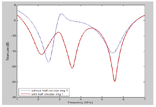
Fig. 2 illustrates the return loss of the antenna with and without half circular ring 1. It can be seen in the figure that half circular ring 1 is employed to generate the second resonant mode at the 3.5-GHz WiMAX band. In particular, the resonance of the 3.5-GHz band is not generated when there is no half circular ring 1. This implies that the length of half circular ring 1 is considerably affected by the characteristics of the return loss in the 3.5-GHz band. Thus, the length of half circular ring 1 should be taken into account while dete rmining the appropriate parameters for the proposed design, in order to achieve the 3.5-GHz operating band. For a good triple-band WLAN/WiMAX operation, half circular ring 1 is introduced.
>
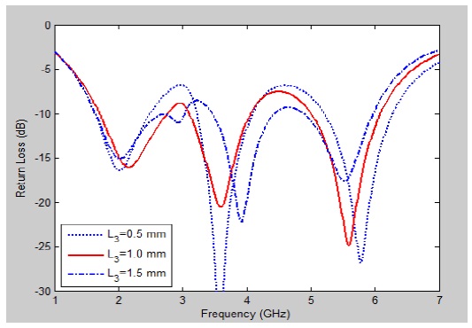
B. Effect of the Width of the L Stub in Half Circular Ring 2 (L3)
Fig. 3 illustrates the return loss for the different values of the L stub length in half circular ring 2. The figure shows that the impedance bandwidth and characteristics of the return loss change slightly when L3 changes from 0.5 mm to 1.5 mm in the required frequency bands. This implies that the L stub in half circular ring 2 is significantly affected by the characteristics of the return loss in all the WLAN/ WiMAX bands. In particular, the impedance bandwidth of the 3.5-GHz bands deviates from the desired frequency bands when L3 is 1.5 mm. Further, the impedance bandwidth of the 2.4/2.5-GHz bands deviates from the desired frequency bands when L3 is 0.5 mm. To design a triple-band WLAN/WiMAX operation, L3 is set at 1.0 mm. Therefore, the width of the L stub in half circular ring 2 should be taken into account while determining the appropriate parameters for the proposed design, in order to achieve the WLAN/WiMAX operating band.
>
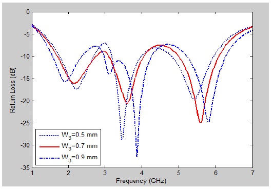
C. Effect of the Gap Width between the Feed Line and the Ground Plane (W3)
Fig. 4 illustrates the return loss for the different values of the gap width between the feed line and the ground plane. It can be seen in the figure that the impedance bandwidth and the characteristics of the return loss changed slightly when W3 changed from 0.5 to 0.9 mm in the required frequency bands. This implies that the gap width is significantly affected by the characteristics of the return loss in all the WLAN/WiMAX bands. To fully satisfy the specifications of the WLAN/WiMAX operation, W3 is set at 0.7 mm.
>
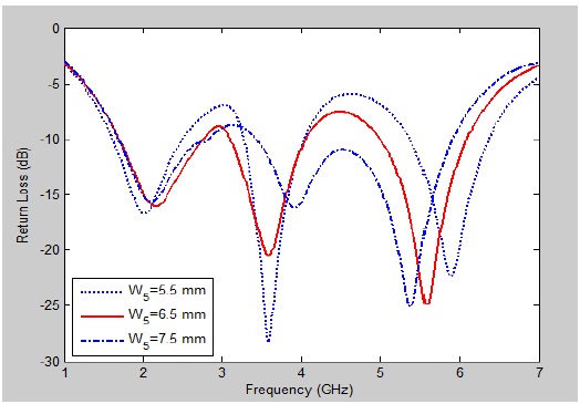
D. Effect of the Length of the L Stub in Half Circular Ring 2 (W5)
Fig. 5 illustrates the return loss for the different values of the L stub width in half circular ring 2. The figure shows that the impedance bandwidth and the characteristics of the return loss change slightly in the 5-GHz bands when L3 changes from 5.5 mm to 7.5 mm. This implies that the length of the L stub in half circular ring 2 is significantly affected by the characteristics of the return loss in the 5-GHz WLAN/WiMAX bands. In particular, the impedance bandwidth of the 5-GHz WLAN/WiMAX bands deviates from the desired frequency bands when W5 is 5.5 mm. Further, the impedance bandwidth of the 3.5-GHz WiMAX bands deviates from the desired frequency bands when W5 is 7.5 mm. To design a triple-band WLAN/WiMAX operation, W5 is set at 6.5 mm. This implies that the length of the L stub in half circular ring 2 is considerably affected by the characteristics of the return loss in the 3.5-GHz/5-GHz bands. Therefore, the length of the L stub in half circular ring 2 should be considered when determining the appropriate parameters for the proposed design, in order to achieve the WLAN/ WiMAX operating band.
>
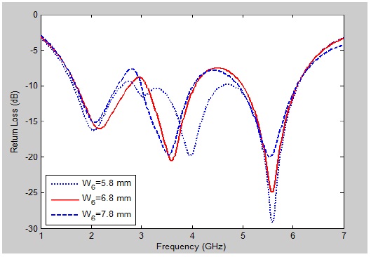
E. Effect of the Length of Half Circular Ring 1 (W6)
Fig. 6 illustrates the return loss for the different values of the length of half circular ring 1. It can be seen in the figure that the impedance bandwidth and the characteristics of the return loss change slightly when W6 changes from 5.8 mm to 7.8 mm in the required frequency bands. This implies that the length of half circular ring 1 is significantly affected by the characteristics of the return loss in the 3.5-GHz WiMAX band. To fully satisfy the specifications of the WLAN/ WiMAX operation, W6 is set at 6.8 mm.
>
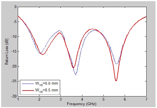
F. Effect of Projection in Half Circular Ring 2 (W12)
Fig. 7 illustrates the return loss with and without projection in half circular ring 2. It can be seen in the figure that the impedance bandwidth and the characteristics of the return loss change slightly when W12 changes from 0 mm to 0.5 mm in all the WLAN/WiMAX bands. This implies that the projection is significantly affected by the characteristics of the return loss in the 2.4/2.5- and 3.5-GHz bands. In particular, the simulation results show that the impedance bandwidth is 915 MHz (1.645–2.575 GHz) in the 2.4/2.5-GHz band when W12 is 0.0 mm. The impedance bandwidth of the 2.4-GHz bands deviates from the desired frequency bands (2.4–2.69 GHz). It should be noted that the impedance bandwidth of the 2.4/2.5-GHz bands is critical for the specifications of the WLAN/WiMAX operation. Thus, the impedance bandwidth of the 2.4/2.5-GHz bands is 1,050 MHz (1.705–2.755 GHz) in the 2.4/2.5-GHz band and satisfies the desired frequency bands when W12 is 0.5 mm. To fully satisfy the specifications of the WLAN/WiMAX operation, W12 was set at 0.5 mm.
The values of the design parameters shown in Fig. 1 were calculated using the optimized Ansoft HFSS software. Thus, the dimensions of the proposed antenna were set as follows: R1 = 4.0 mm, R2 = 6.0 mm, L1 = 30.0 mm, L2 = 2.0 mm, L3 = 1.0 mm, L4 = 1.0 mm, L5 = 2.0 mm, L6 = 13.0 mm, W1 = 22.0 mm, W2 = 9.3 mm, W3 = 0.7 mm, W4 = 2.0 mm, W5 = 6.5 mm, W6 = 6.8 mm, W7 = 3.0 mm, W8 = 1.0 mm, W9 = 2.0 mm, W10 = 0.5 mm, W11 = 5.8 mm, W12 = 0.5 mm, and h = 1.0 mm. From the simulation results, the following -10 dB impedance bandwidths were derived: 1,050 MHz for the 2.4/2.5-GHz band (from 1.705 GHz to 2.755 GHz), 930 MHz for the 3.115-GHz band (from 3.115 GHz to 4.045 GHz), and 1080 MHz for the 5-GHz band (from 5.005 GHz to 6.085 GHz).
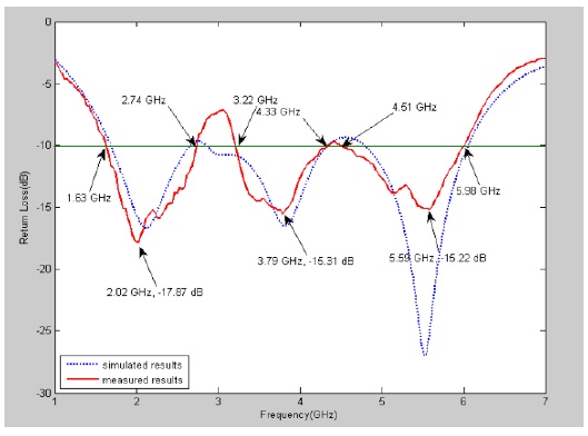
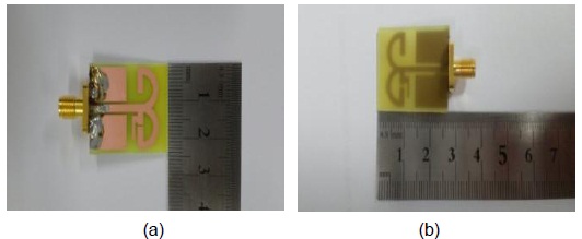
On the basis of the optimal dimensions, a prototype of the triple-band antenna was fabricated and experimentally investigated. Fig. 8 shows the photograph of the fabricated antenna. Fig. 8(a) and (b) show the front and back view of the fabricated antenna, respectively. The measured results were obtained by using the Anritsu MS4644A vector network analyzer at Silla University, Busan, South Korea. The far-field radiation patterns and gains were measured using a far-field anechoic absorber. Fig. 9 shows the simulated and measured
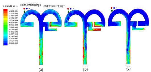
To enable a better understanding of the excitation behavior of the proposed antenna, the surface current density excitations along the three branch strips in the cases of the three resonant frequencies of 2.15, 3.60, and 5.60 GHz were studied and are displayed in Fig. 10(a)–(c), respectively. It can be clearly seen from these figures that the current distribution at these three frequencies is different. For the first resonant mode (Fig. 10(a)), a large surface current density was observed along the end of the openended half circular ring 2, whereas for the second mode (Fig. 10(b)), the current density distribution became more concentrated along the end of the open-ended half circular ring 1, the end of the open-ended half circular ring 2, and the L strip stub. Thus, it is implied that the excitation of the 2.4/2.5-GHz band was contributed by the open-ended half circular ring 2 and that the excitation of the 3.5-GHz band was contributed by the open-ended half circular ring 1, open-ended half circular ring 2, and the L strip stub. These results were verified by simulation results. From Figs. 2, 3, and 5, it can be noted that the 3.5-GHz WiMAX band was significantly affected by the L strip stub and open-ended half circular ring 1. For the third resonant mode (Fig. 10(c)), the current distribution became more concentrated along the L strip stub. Thus, it is implied that the excitation of the 5-GHz band was contributed by the L strip stub. However, three cases of current distribution had a common feature in that a large surface current density was concentrated along the microstrip feed line.
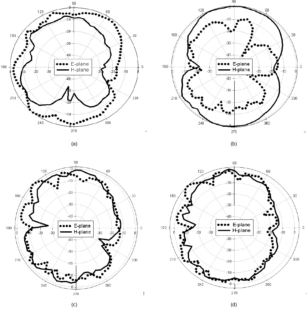
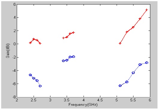
Fig. 11 shows the measured 2D far-field radiation patterns in the E-plane (x–z plane) and H-plane (y–z plane). Fig. 11(a), (b), (c), and (d) show the 2D radiation patterns at 2,400, 3,500, 5,300, and 5,700 MHz, respectively. On the basis of these radiation patterns, the proposed antenna displayed nearly omnidirectional radiation characteristics in the H-plane and monopole-like radiation pattern characteristics in the E-plane at the considered frequencies. Fig. 12 shows the 2D measured antenna peak and average gain for the frequencies across the 2.4/2.5-GHz, 3.5-GHz, and 5-GHz bands. The blue line represents the average gains, and the red line represents the average gains of the proposed antenna, respectively. The 2.4/2.5-GHz band had an antenna peak gain level of about 1.63–3.0 dBi, and the 3.5-GHz band, about 0.73–1.77 dBi. The measured antenna gain levels were about 2.37–4.39 dBi in the 5-GHz band.
The 2.4/2.5-GHz band had an antenna average gain level of about –2.73 to –2.26 dBi, and the 3.5-GHz band, about – 5.34 to –3.77 dBi. The measured antenna gain levels were about –2.92 to –1.16 dBi in the 5-GHz band.
A circular-ring planar monopole antenna with a half circular ring and a ground slot for WLAN/WiMAX applications was proposed. The antenna has a simple structure and a compact size of 22.0 mm × 30.0 mm × 1.6 mm. By adding the two half circular ring patches, the antenna can excite three resonant modes. The effects of varying dimensions of the key structure parameters on the proposed antenna’s performance were also studied herein. In particular, half circular ring 1 was significantly affected by the characteristics of the return loss in the 3.5-GHz band. The projection was also significantly affected by the characteristics of the return loss in the 2.4/2.5- and 3.5-GHz bands. Furthermore, the results of the studies on the surface current distributions of the operating frequency bands were discussed herein. The measured return loss characteristics showed that the obtained impedance bandwidths were 1110 MHz (1.63–2.74 GHz), 1110 MHz (3.22–4.33 GHz), and 1470 MHz (4.51–5.98 GHz), respectively, which are suitable for WLAN and WiMAX applications. In addition, this monopole antenna exhibited a nearly omnidirectional radiation pattern in the H-plane and a dipole-like radiation pattern in the E-plane. Further, measured gains were obtained in the operating bands.