This paper dealt with the condensing technology of an LED light source that uses a parabolic reflector to replace a searchlight equipped with a xenon lamp. A ray-tracing simulation was conducted to analyze the influence of the diameter of the reflector and the size of the light source on light condensing. The combination of a parabolic reflector with a diameter of 620 mm and a focal distance of 220 mm, and a 9 mm multi-chip package (MCP) with a luminous flux of 7,000 lm showed the narrowest beam angle. The luminous intensity at the center was measured at 7.7×10⁶ cd. The distance between the light source and the point where the illuminance was 1 lx was calculated to be 2.8 km. The power consumption of the system was 95 W, which is only 9.5% of that of the 1 kW xenon searchlight, and the beam angle was 1.03°. In a site experiment, it was confirmed that the light ray reflected from the LED searchlight proceeds forward without any diffusion because of the narrow beam angle.
Light emitting diode (LED) has been regarded as a light source with a higher efficiency and longer lifetime than the conventional incandescent and discharge lamps such as fluorescent lamps and metal halide lamps. Widespread applications have been found for LEDs in the lighting industry within a short period of time. The light efficacy of an LED is over 80%, while that of an incandescent lamp and a fluorescent lamp are 5% and 40%, respectively [1,2]. The size of the domestic market for LEDs is estimated to increase to 17.7 trillion won in 2018, with an average growth rate of 21% per year, from 2.1 trillion won in 2010. When the conventional light sources with a domestic market share of 30% are replaced by LEDs, the power consumption will be reduced by 16,021 GWh per year, amounting to savings of about 1.6 trillion won. This is consistent with the global environmental regulation policy to reduce carbon dioxide emission by 6.8 million tons [3]. A xenon lamp of between 1 kW and 3 kW is currently used as a high-power searchlight on land or on ships in the sea. However, its inherent purpose is difficult to meet because its light source life is quite short - 350 hours, and it takes about ten minutes for full-lighting and restart.
In this paper, the design method of a high condensing LED searchlight with a parabolic reflector is proposed as a basic study for replacing the xenon searchlights used in coastguard stations and ships.
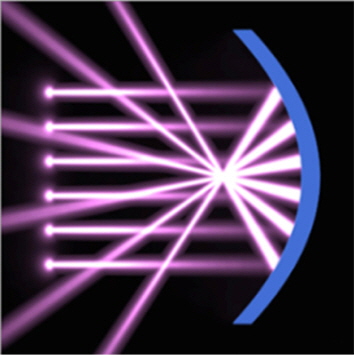
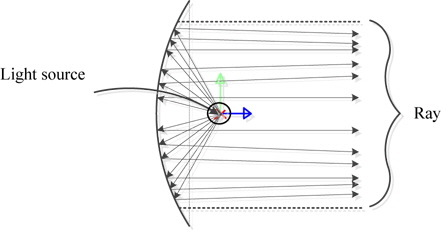
A parabolic reflector has been used to collect light or radio waves at a point in the solar concentrator and radio antenna [4]. The concept of condensation is shown in Fig. 1. If the function of a parabolic reflector is reversed, the light emitting from the point will be reflected in parallel, and the beam will acquire the maximum luminous intensity at the center of the LED searchlight [5,6].
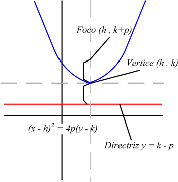
The parabolic reflection and focal distance are shown in Fig. 2 and defined by equation (1), where


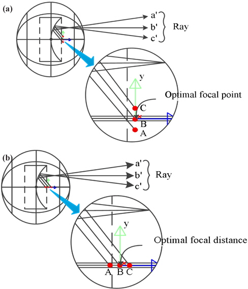
The optimal focal point is proposed by ray-tracing simulation as shown in Fig. 3(a), since an LED as a surface light source is depart from the focus of the parabolic reflector, while a point light source is satisfied with the function of a parabolic reflector as shown in Fig. 2 [7].
Point A is the ray coming above the focal point into the top of the parabolic reflector, point B is the ray coming in line with the focal point into the parabolic reflector, and point C is the ray coming below the focal point into the bottom of the parabolic reflector.
Ray b' is parallel with the horizontal line from the center of the parabolic reflector, while rays a' and c', above and below the focus respectively, are diffused or focused at a point on the parabolic reflector [8]. The simulation result shows that the diameter and the size of the light source should be reduced to reflect the rays in parallel.
Figure 3(b) shows the ray direction in accordance with the focal distance from the x-axis. Ray a', which is emitted from the point closer to the reflector is diffused and ray c', which is emitted from a point some distance from the reflector, is focused at a point. Since rays a' and c' are not suitable for searchlights, ray b', which is parallel, should be reflected by changing the focal distance.
2.2 Calculation of luminous intensity
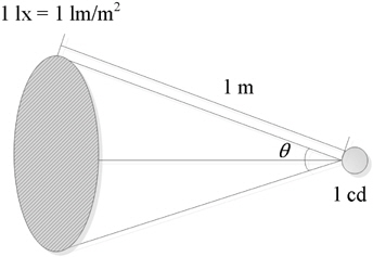
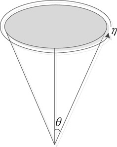
The performance of the searchlight is evaluated using the luminous intensity at the center. Luminous intensity is defined as the magnitude of luminous flux emitted inside a solid angle from a light source in a particular direction, as shown in Fig. 4. It is expressed in cd [candela]. In this paper, the luminous intensity was calculated with luminance, luminous flux, and solid angle to evaluate the performance of the searchlight.
Luminous flux is the measure of the perceived power of light in the range of 380 nm ~ 780 nm, and is expressed in lumen. Therefore, in the case of other light sources except for the point sources, luminous intensity could be calculated using equation (4). Where

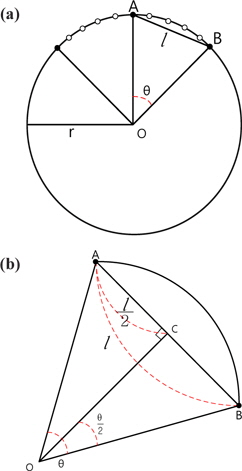
The solid angle

For circular rotation with angle

If equation (4) is substituted into equation (6), equation (7) is given by

Finally, the luminous intensity
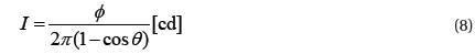
In equation (8), if the total luminous flux of a light source and the beam angle of 2
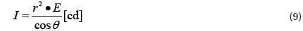
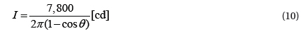
When the beam angle is not given, equation (9) is used to calculate the luminous intensity using the center illuminance. If
2.3 Experimental configuration
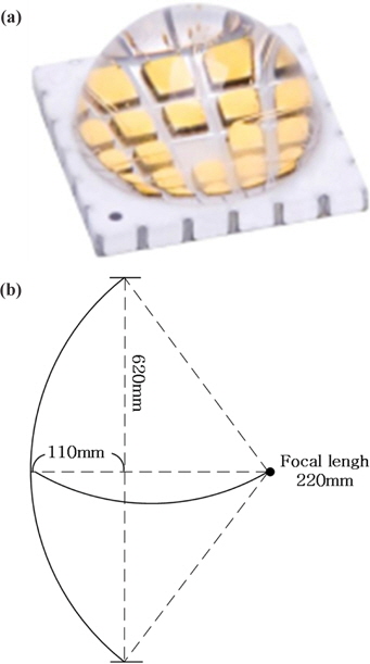
As a light source, a 9 mm in diameter and 95 W multi-chip package (MCP) was adopted to the system. Fig. 6 shows the MCP and the parabolic reflector of 620 mm in diameter, 110 mm in depth and 220 mm in focal distance.
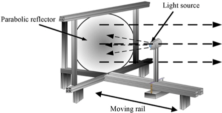
Figure 7 shows the configuration of the experimental system. The LED searchlight can collect light through the moving rails by changing the focal distance of the light source and fixing the parabolic reflector. The center height of the parabolic reflector and the MCP were designed to be 310 mm. The water-cooling device was designed to improve the effect of heat dissipation because the high-power LED of 95 W was attached to the aluminum plate.
Figure 8 presents the ray-tracing simulation result with the designed light source and parabolic reflector. The simulation result confirmed that the rays were reflected in parallel [10].
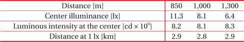
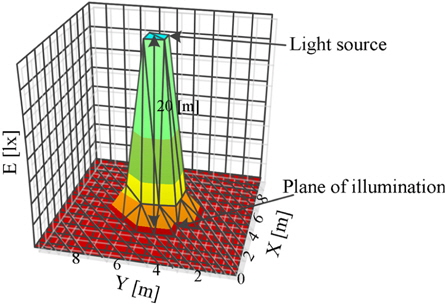
The maximum illuminance at the center was 40,110 lx in an area of 10 m2 and at a distance of 20 m from the light source as shown in Fig. 9 [11].
To obtain the beam angle and the luminous intensity at the center, an experiment was carried out as shown in Fig. 10. The searchlight was placed at the central O point and the maximum illuminance was measured at point A, which was located 20 m from the center. The distance
When the value of the beam angle
The luminous intensity at the center,

Using equation (11),
[Table 1.] Optical performance of the prototype LED searchlight.

Optical performance of the prototype LED searchlight.
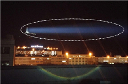
Figure 11 shows a photograph of the experiment where the light was reflected to the top of a mountain, which was about 800 m from the LED searchlight. As the beam angle of the searchlight calculated based on Fig. 10 reaches 1.03°, the light ray proceeds forward without any diffusion.
This paper described the development of a high condensing LED searchlight, using a parabolic reflector to replace a search-light with a 1 kW xenon lamp. The light condensing system was composed of an LED package, a parabolic reflector, and a water-cooling device. The luminous intensity at the center measured 20 m from the light source was 7.7×10⁶ cd. The distance between the light source and the point where the illumination intensity was 1 lx was calculated to be 2.8 km.
The power consumption of the system was 95 W, which is only 9.5% of the 1 kW xenon searchlight, and the beam angle was 1.03°. In a site experiment, it was confirmed that the light ray proceeds forward without any diffusion because of the narrow beam angle.
The diameter of the reflector is 620 mm, but this could be reduced to 280 mm by modifying the radius of curvature, depending on the diameter and the beam angle of the LED package. The well designed LED searchlights have advantages including an instantaneous turn-on, a low power consumption, and a light weight.