본 논문은 컬러 클러스터 MIMO 기술을 적용하여 육상과 해상 간의 저비용 고속 무선 데이터 전송이 가능한 해상 가시광 통신 시스템을 제안한다. 제안하는 시스템은 각 컬러 클러스터에 50개의 RGB LED 로 구성되며, 온-오프키잉을 사용하여 변조한다. 수신기에서는 선택적 합성기술을 수행하여 컬러 클러스터의 다이버시티 효과를 얻어 비트오율 개선을 제공한다. 성능 실험에서는 해상 채널 구성을 위해 대기 난류 조건에서 바다 상태 데이터 (파고, 풍속 등)를 Pierson-Moskowitz 및 JONSWAP 스펙트럼에 적용하여 구현하였으며 해상 링크 품질을 통신거리와 비트 오율을 통해 분석하였다. 시뮬레이션 결과를 통하여 제안한 시스템은 국제항로표지협회의 해상 부표식에 충족하고, 고출력 LED를 사용하기 때문에 충분한 조명을 동시에 제공할 수 있는 효율적인 해상 가시광통신 기술임을 보여주고 있다.
Recently, the growing shipping industry has been witnessed in terms of total trade volume. To some degree, advanced communication technologies have contributed to a significant reduction in maritime accidents over the past few years. Even so, the risk of maritime accidents always lies in the shipping industry and it grows steadily as larger and faster ships are more common. The maritime buoyage system defined by International Association of Lighthouse Authorities (IALA) is established all over the world [1]. The system standardizes the size, shape and usage policies of buoys, beacons and lights located along coasts and waterways to guide ships and boats. There are two international buoyage regions A and B defined by IALA, where lateral marks differ. The current geographical divisions of these two regions are shown in [1]. Lateral marks in region A use red and green colors to indicate port and starboard sides of channels, respectively. In region B, these colors are reversed with red to starboard and green to port.
The conventional maritime wireless communications at sea rely mainly on satellite links that are expensive and relatively slower than HF and VHF. Radio frequency (RF) based maritime communication systems satisfy communication and navigation needs at the expense of high cost and low transmission speed. Moreover, it suffers from insufficient dedicated operation spectra.
On the other hand, visible light communication (VLC) has recently attracted much attention from researchers and industry, due to its high potential for various applications. VLC uses light emitting diodes (LEDs) as transmitters and photo diodes (PD) as receivers, operating at a wavelength range of 380-780 nm [2,3]. The fast switching characteristics of LEDs are utilized for communication and illumination simultaneously. In maritime environments, this VLC technology can be applied to existing infrastructure such as lighthouses and beacons. Most of the lighthouses that use electric lamps are switched to LEDs nowadays as life span, efficacy and power consumption of an LED is far better than conventional electric lamp.
In order to overcome the limitations of conventional maritime communications, VLC has recently been considered. The Lighthouse Sub Project started activity from September 2007 for the realization of the long-distance VLC using an existing LED lighthouse [4]. The project was able to record a transmission rate of 1.2 kbps at distance of 1 km and a transmission rate of 1 kbps at a distance of 2 km by using image sensor based VLC. However, as this project was conducted in silent sea conditions, it failed to provide a comprehensive study on the feasibility of maritime VLC (MVLC) and thus further investigations under various ocean and atmospheric conditions are necessary.
A first realistic analysis of MVLC was reported using a spectrum model called Pierson-Moskowitz with sea state parameters applied [5]. Another spectrum model called JONSWAP was also investigated for its accuracy and efficiency and compared with the Pierson-Moskowitz model [6]. However, these studies do not consider atmospheric turbulence that is important and also common in maritime environments. Therefore, they are not comprehensive in terms of the analysis of the potential of MVLC.
With the motivation for providing an efficient VLC link under various atmospheric conditions and sea states in mind, we present a shore-to-sea VLC using color clustered multiple-input and multiple-output (MIMO). The proposed MVLC offers a low-cost, high-speed wireless link in shore-to-sea maritime environments. Each color cluster is comprised of 50 red, green and blue (RGB) LEDs and is modulated using on-off-keying (OOK) [7]. We employ sea states (wave height, wind speed, etc.) data from Pierson-Moskowitz spectrum model and JONSWAP spectrum model under atmospheric turbulence conditions to evaluate the performance of the proposed scheme in maritime environments. Selection combining is performed at the receiver, producing diversity effect within that color cluster, thereby giving us the MIMO diversity gain and improved bit error rate (BER) performance. Based on the simulation model, the maritime link quality is analyzed in terms of coverage distance and BER performance.
The rest of this paper is organized as follows. Section II introduces the proposed system together with channel model. Performance analysis and simulation results are presented in Section III. Finally, Section IV shows conclusions drawn from the investigations.
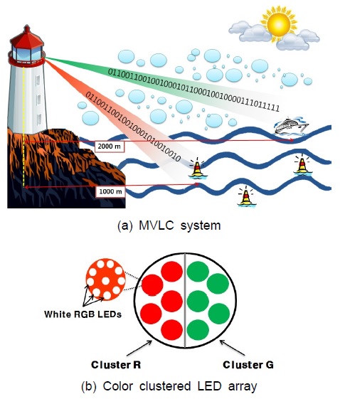
Fig. 1(a) depicts the MVLC system under consideration. The lighthouse (base station) shown in Fig. 1(a) consists of a power LED array that provides coverage to a very large area. The sea transceivers (beacons, ships) are composed of an LED array for transmission and photodiodes and filters for reception. A VLC link is established between the lighthouse and the beacon, considering sea state and atmospheric turbulence.
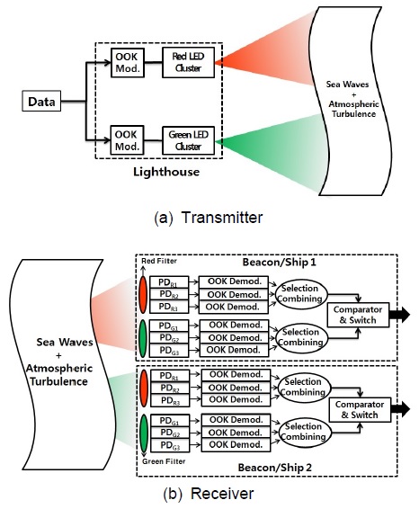
The maritime system comprises various marks such as lighthouses, beacons, laser markers etc., which act as visual aids for ships and boats. Providing illumination and direction to ships are another aid of lighthouse and beacons. For this purpose, we designed a power LED array that consists of two color clusters, i.e. red and green, of LEDs as shown in Fig. 1(b). Each color cluster consists of 50 RGB LEDs where data bits for communication are modulated and transmitted using individual color from LEDs. The red and green colors used in the proposed scheme for color clustered MIMO are in line with the maritime buoyage system defined by IALA. Fig. 2(a) shows the block diagram of the transmitter used in the proposed system. Input binary sequence is divided into two parallel streams, one for each color cluster. The data stream is modulated in each cluster by using the OOK modulation scheme, where each LED in a cluster transmits the same data stream, as shown in Fig. 2(a). At the receiver in Fig. 2(b), the three photodiodes in each color cluster are installed in addition to the color filter.
The received signal from each photodiode is compared with the signals received from the other photodiodes, i.e. selection combining [7]. Thus, the color clustered MIMO method increases diversity gain and contributes to a significant improvement in the performance of the proposed MVLC system.
2.2. Maritime Wireless Channel Modeling
The wireless channel properties are highly affected by the propagation environment. Hence, for designing a communication model in a maritime environment, it is essential to consider the parameters of the propagation environment. A maritime communication environment has different properties and challenges, compared with its terrestrial counterpart. The maritime environment is mainly characterized by sea waves and atmospheric turbulence (i.e. Maritime channel). These will affect the antenna gain, received signal power and different signal reflections from the sea surface [8].
2.2.1. Sea waves
Sea waves are generated by the effect of wind over the ocean surface. If the wind speed is faster and wind duration is longer, the generated waves will be bigger. The sea spectra are used to provide an insight into the movement of sea surface in oceanography and ocean engineering. The simplest is the one which is proposed by Pierson and Moskowitz [9]. They assumed that if the wind blew steadily for a long time over a large area, the waves would come into equilibrium with the wind. This is the concept of a fully developed sea. Another typical mathematical sea wave model is the renowned Joint North Sea Wave Observation Project (JONSWAP) power spectral density function [10]. This model is the product generated from analyzing the data collected during the JONSWAP. It continues to develop through non-linear, wave-wave interactions even for a very long time and distance.
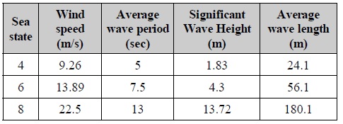
Since the real-time data is not available for the present simulations, we employ sea state data from Pierson-Moskowitz spectrum model and JONSWAP spectrum model as they were developed from measurements of various sea parameters. The sea state parameters applied in the present study are shown in Table 1. According to the Pierson-Moskowitz and JONSWAP spectrum models, these parameters were directly applied in the simulation to represent roughness of the sea states.
[Table. 1] Sea state Parameters

Sea state Parameters
2.2.2. Atmospheric turbulence
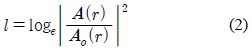
The atmospheric turbulence degrades the performance of a VLC link, because it causes the received signal to vary randomly according to signal fading. The fading strength depends on the link length, the wavelength of the optical radiation and the refractive index structure parameter, Cn2, of the channel. The log-normal distribution is generally used to model the fading associated with the weak atmospheric turbulence regime [11]. This model is mathematically tractable and it is characterized by the log irradiance variance σl2. The log irradiance variance σl2 can be calculated as [12]:
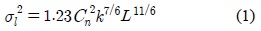
where
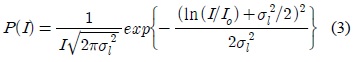
The log-normal model assumes the log intensity l of the light traversing the turbulent atmosphere to be normally distributed.

The intensity in the turbulent medium is
Hence,
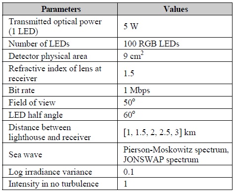
Simulations have been carried out to analyze the link performance of the proposed shore-to-sea MVLC using color clustered MIMO. Performance is evaluated in terms of BER with respect to distance between base station (Lighthouse) and receivers. We used the simulation parameters shown in Table 2 and obtained the BER performances for the proposed MVLC system. It should be noted in Table 2 that the transmitter, i.e. lighthouse, is employed in accordance with the general requirement of lighting for lighthouse by IALA. In addition, a large photodetector area of 9 cm2 is considered to improve the performance under various sea conditions and is also practical as a photodetector with a physical area of 2.8 x 2.8 cm2 is commercially available [13].
[Table. 2] Simulation Parameters

Simulation Parameters
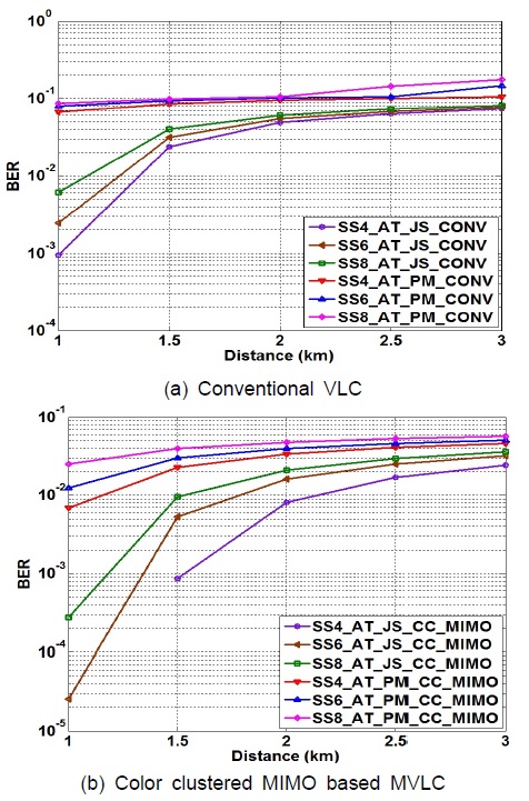
Fig. 3(a) shows the analysis of a conventional MVLC system under various sea states and atmospheric turbulence using the OOK modulation technique. It can be observed from the simulation results that the JONSWAP spectrum model with sea state 4 only appears appropriate for communication up to approximately 1 km using the underlying LED and photo detector combination, whereas the performance severely degrades in Pierson-Moskowitz spectrum model. It is also observed that at higher sea states the transmission channel condition becomes hostile from high wind speed, wave height, etc., resulting in degraded performance as shown in Fig. 3(a).
Fig. 3(b) shows the analysis of the MVLC link using the color clustered MIMO. It is apparent that the BER performance of the proposed scheme is significantly improved compared with the conventional MVLC based simple OOK transmission. In particular, the JONSWAP spectrum model offers a BER of 10-3 at a distance of 1.5 km for sea state 4. At this performance criterion, the conventional VLC achieves a distance of 1km. Therefore, the proposed color clustered MIMO scheme can increase the distance of transmission in MVLC environments without increasing the transmission power. As the distance increases, it is obvious that the BER performances degrade. This degradation can be compensated using a powerful error detection and correction coding.
The MVLC system with the color clustered MIMO is proposed and analyzed relative to distance based on Pierson-Moskowitz and JONSWAP sea spectrum models under atmospheric turbulence. The proposed system encompasses VLC using LEDs and photodiodes for the transmission between shore and sea. The performances relative to the sea states and atmospheric turbulence vary in terms of distance. It is found that at high sea states, a more rigorous transmission scheme needs to be employed. Recognizing the limitations of the existing maritime communication networks such as a lack of bandwidth and the installation of expensive network infrastructure, the proposed color clustered MIMO based MVLC can be an attractive candidate for an advanced maritime broadband communication system.