Mobile and wireless communications, including Bluetooth, wireless local area network (LAN), and 4G long-term evolution (LTE) mobile communication systems have become very popular. One objective of mobile and wireless communications is to increase the transmission rate and the reliability of end-to-end communication as much as those of wireline communications. However, a deep fading phenomenon caused by multi-path transmission frequently occurs in a wireless channel environment, and it adversely affects communication reliability. To overcome channel fading in wireless communication, a space diversity scheme is commonly used. Space diversity is configured using multiple antennas. However, it is very difficult to install multiple antennas in a tiny mobile terminal in a wireless or mobile communication system. To overcome this limitation, a cooperative communication scheme was introduced [1], and the concept of space diversity used in this scheme was called ‘cooperative diversity’ to differentiate it from the existing space diversity. When a sender node and a receiver node are somewhat distant from each other or a channel characteristic between the two communication nodes is not particularly good, a helper node, positioned between them, participates directly to improve the communication environment between the sender node and the receiver node. This is a typical concept in cooperative communication. In order to estimate how much cooperative communication can improve the system throughput performance, let us consider an example network with the IEEE 802.11b system [2], where receiving and sending transmission rates of only 2 Mbps are allowed when a sender node and a receiver node are communicating directly with each other. However, if any arbitrary node between them takes part in the communication as a helper node, two channel transmission rates between the sender node and the helper node, and between the helper node and the receiver node can be up to 11 Mbps, for example. In this exemplary environment, although twohop communication is performed, the effective transmission rate becomes (1/11 + 1/11)−1 = 5.5 Mbps, which is significantly better than the 2 Mbps in the direct communication.
In this paper, we propose a new medium access control (MAC) protocol for cooperative communication, including a method to select a helper node. We then conduct a performance evaluation to present the comparative performance results of the proposed protocol and three existing cooperative MAC protocol schemes. The rest of this paper is organized as follows: In Section II, we describe the research trends for the existing MAC protocols for cooperative communication that include helper node selection schemes. In Section III, we explain the new MAC protocol for cooperative communication proposed in this paper. The performance evaluation results achieved via a computer simulation experiment are presented in Section IV, followed by the conclusion in Section V.
In a cooperative communication scheme, it is vital to determine how to select a helper node. According to the time when a sender node selects a helper node for cooperative communication, helper node selection schemes can be classified into proactive and reactive schemes. If a helper node is already selected at the time of data packet generation at sender nodes, the selection scheme is a proactive selection scheme. On the other hand, if the process to find a helper node starts after the request-to-send (RTS) and clear-to-send (CTS) frame exchange process, the selection scheme is a reactive selection scheme. Early studies on cooperative communication typically used a proactive selection scheme. However, this scheme is complicated. It results in an increased network load because every communication node has to maintain its relay table by overhearing all control frames passing by and then, share the relay table information with its neighboring nodes by broadcasting extra control frames periodically. Furthermore, a helper node, selected in advance, might not be optimal when the sender node sends a data frame in a wireless channel because the wireless channel characteristic changes quickly. The relay distributed coordination function (rDCF) scheme proposed in [3] and the CoopMAC scheme proposed in [4] adopted a proactive selection scheme, in which a relay table was created to manage information about suitable helper nodes nearby.
Several MAC protocols with a reactive helper node selection scheme have also been proposed for cooperative communication [5-7]. The cross-layer triple busy tone multiple access (CTBTMA) scheme proposed in [5] used a utility function and three busy tones to determine an appropriate helper node. When an RTS and a CTS frame are exchanged between a sender node and a receiver node for data transmission, any candidate helper node can participate in the helper node selection procedure by calculating the utility function according to the allowable channel transmission rates between the candidate node, the sender node, and the receiver node. A utility function is the maximum effective transmission rate that can be used to send data frames via the current wireless communication channel. Any candidate helper node can send a busy signal when its utility function is larger than that calculated at the sender node for direct communication with the receiver node. The larger the utility value, the longer each candidate helper node transmits a busy signal, and thus, the candidate helper node that transmits the longest busy signal survives this helper node selection process and becomes the final helper node by transmitting a ready-to-help (RTH) frame.
In [6], a cooperative MAC protocol with a reactive helper node selection scheme was proposed, where a composite cooperative transmission rate (CCTR) was used to select an appropriate helper node. Candidate helper nodes calculate the CCTR value first and are then classified into several groups according to the CCTR. The first competition is carried out between the groups, and then, a competition between members of the chosen group follows. The competition uses a timer, and the timeout value of the timer held by a candidate node is assigned in inverse proportion to the CCTR value. When an activated timer expires, a corresponding candidate node transmits a group indication (GI) signal. However, if a corresponding node knows that other candidate nodes transmitted a GI signal before its timer expires, the corresponding node leaves this helper node selection competition. If more than one candidate node transmitted a GI signal to a GI slot, then these corresponding nodes continue their competition by using a member indication (MI) signal in a similar way as a GI signal. While a candidate helper node in [5] is chosen as a final helper node at the end of the competition by transmitting the longest busy signal, a candidate helper node in [6] is selected as a final helper node at the beginning of the competition by using a timer.
In [7], a cooperative relay-based auto rate (CRBAR) scheme was proposed as a cooperative MAC protocol with a reactive selection scheme. In this scheme, candidate helper nodes that could improve system performance via cooperative communication participate in the helper node selection competition by using a p-persistent carrier sense multiple access (CSMA) scheme. Although this scheme is simpler than the schemes proposed in [5,6], its weakness is that it cannot guarantee the selection of the helper node that has the best wireless channel environment.
In [8], the researchers (via a computer simulation experiment) compared the performance of three systems with reactive helper node selection schemes on a wireless channel without channel fading. The performance evaluation results showed that the three-step helper node selection scheme proposed in [6] has the best performance.
Finally, this paper is an extended version of the previous our work [9,10]. It presents a more concrete and precise explanation of the busy tone cooperative medium access control (BT-COMAC) protocol and provides more comprehensive performance comparison results with the other cooperative MAC protocols.
In this section, the BT-COMAC protocol that adopts a reactive helper node selection scheme is described in detail. The helper node selection process used in a BT-COMAC protocol consists of a three-step competition similar to that proposed in [6]. The three steps of this competition are as follows: busy indication (BI) slot competition, contention indication (CI) slot competition, and competition via
>
A. Overall Description of BT-COMAC
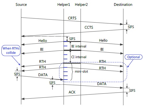
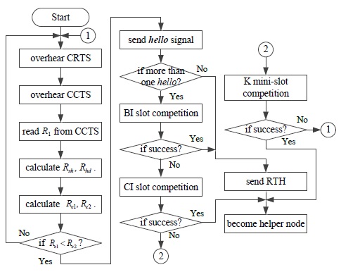
Fig. 1 shows the entire process of exchanging a DATA frame among a helper node, a source node, and a destination node. In this process, a source node sends a cooperative RTS (CRTS) frame to a destination node if it has a DATA frame to send. Once a destination node receives the CRTS frame successfully, it replies with a cooperative CTS (CCTS) frame. A destination node piggybacks the allowable transmission rate between the source node and the destination node in the CCTS frame, which can be calculated on the basis of the received power strength measured when receiving the CRTS frame.
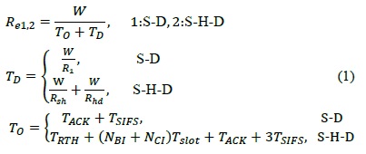
After receiving both the CRTS frame and the CCTS frame, the candidate helper nodes that are positioned between the source node and the destination node and that are ready to participate in cooperative communication calculate two allowable transmission rates,

In Eq. (1),
After one appropriate helper node is decided by using the helper node selection scheme, which is described in the following subsection, the source node will transmit its DATA frame to the newly selected helper node, and then, the helper node will forward the received DATA frame to the destination node. This entire data transmission procedure will end after the destination node sends the ACK frame to the source node directly.
>
B. Three-Step Helper Node Selection Procedure
Fig. 2 schematically illustrates the operation of the threestep helper node selection scheme. After receiving the CRTS frame and the CCTS frame, each candidate helper node compares two different effective transmission rates,
In the BT-COMAC scheme, a candidate helper node that has greater received power strength is assigned to a front slot to send a BI signal among other candidate helper nodes. If more than one candidate helper node sends a BI signal to a specific BI slot, the corresponding candidate helper nodes re-compete during the following CI slot competition. During a CI slot re-competition, a helper node selection competition is carried out using an RTH frame. If a final helper node is not decided in this step (e.g., when more than one candidate helper node sends an RTH frame), the final competition will be performed during the
>
C. Selection of BI and CI Slots
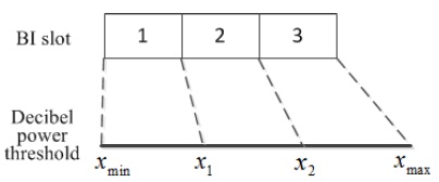
To explain how to select the BI and CI slots, let us define a new metric called decibel power, as expressed in Eq. (2). Because of the large fluctuation property of the received power strength values depending on the distance between two nodes, a logarithm is used.

In the above equation, is the received power strength measured at the
Fig. 3 shows the relationship between BI slots and reference decibel power values when
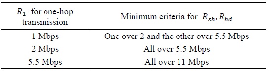
[Table 1.] An example of minimum participation criteria for cooperative communication

An example of minimum participation criteria for cooperative communication
[Table 2.] Transmission rates and ranges
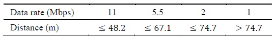
Transmission rates and ranges
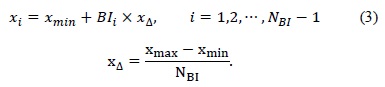
The slot boundary values

Each candidate helper node chooses a suitable BI slot by comparing the decibel power value calculated by it and the slot boundary values shown in Fig. 3. For example, if the decibel power value of a corresponding candidate helper node lies between
If the number of candidate helper nodes that sent a BI signal to a specific BI slot is only one, subsequent CI slot and
IV. PERFORMANCE EVALUATION AND RESULTS
>
A. Network Topology and Channel Modeling
The example network topology used for the performance evaluation consists of a communication service area with a 100 m × 100 m square and
The relationship between transmission distance and path loss in a slow fading wireless channel environment is represented by Eq. (4) [12]:

where
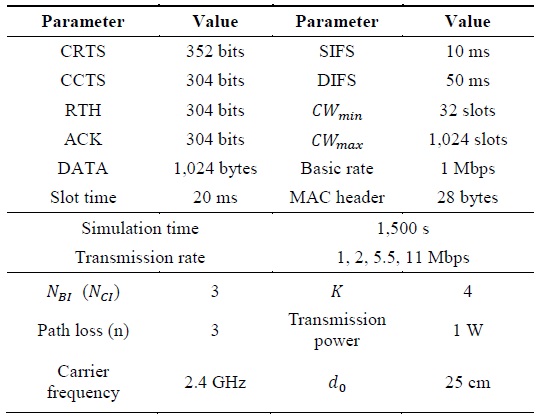
Helper nodes that satisfy the minimum participation criteria in Table 1 were assumed to always participate in cooperative communication. A saturated traffic model, where a source node always has DATA frames to send in its buffer, was adopted as our traffic model to calculate the maximum system throughput. Two performance measures, system throughput and average channel access delay time, were used for the performance comparison. The system throughput is defined as a value of the total length of DATA frames in bits that are sent successfully during the computer simulation experiment divided by the computer simulation experiment duration. The channel access delay time is defined as the average delay time between the time of starting a channel competition to send a DATA frame and the time of receiving an ACK frame successfully from a destination node. We compare the new BT-COMAC protocol with the three cooperative MAC protocols proposed in [5-7] and a wireless LAN without cooperation, which will be called the DCF in the following paragraphs. Table 3 shows the system parameters used for the performance evaluation, which have the same values as those used in [4].

System parameters
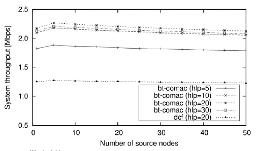
Fig. 4 shows the system throughput changes of the BT-COMAC scheme due to changes in the number of source nodes when the number of helper nodes is 5, 10, 20, and 30. This figure also shows how much the new BT-COMAC scheme can enhance its system throughput performance as compared to the traditional DCF scheme. Because the traditional DCF scheme does not use cooperative communication, its system throughput performance is not dependent on the number of helper nodes. Since a saturated traffic model is used, this scheme has the best system throughput performance when there are not many source nodes in the communication range (that is, five source nodes in this example). As the number of helper nodes increases, the system throughput also tends to increase until the number of helper nodes approaches 20, and then, it tends to decrease as the number of helper nodes increases to more than 20.
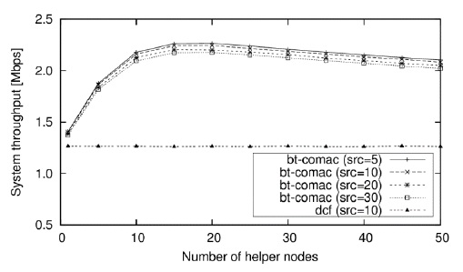
Fig. 5 shows the system throughput changes of the BT-COMAC scheme due to changes in the number of helper nodes when the number of source nodes is 5, 10, 20, and 30. This figure shows that the BT-COMAC scheme enhances its system throughput performance by about 80% as compared to the traditional DCF scheme.
It is clear from this result that this scheme has the maximum system throughput when the number of helper nodes is approximately 20, which we already know from Fig. 4. When the number of helper nodes becomes more than 20, the probability of failure in the helper node selection process increases because the number of helper nodes with a similar size decibel power as the other nodes is likely to be more than one.
Fig. 6 shows the channel access delay changes of the BT-COMAC scheme due to changes in the number of helper nodes when the number of source nodes is 5, 10, 20, and 30. It is also shown that the BT-COMAC scheme enhances the channel access delay performance as compared to the traditional DCF scheme because of cooperative communication. As the number of helper nodes increases, the channel access delay of the BT-COMAC scheme tends to decrease until the number of helper nodes is approximately 20. When the number of helper nodes is greater than 20, the probability of the helper node selection failure tends to increase, and then, source nodes return to the beginning to send an RTS frame for direct communication with their destination nodes, which increases the channel access delay.
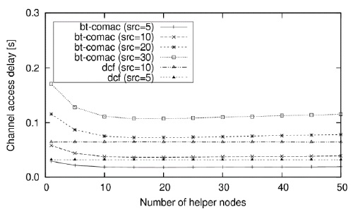
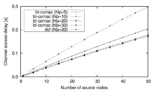
Fig. 7 shows the channel access delay changes of the BT-COMAC scheme due to changes in the number of source nodes when the number of helper nodes is 5, 10, 20, and 30. The BT-COMAC scheme is also compared with the traditional DCF scheme, and it is shown that the BT-COMAC scheme has a significantly enhanced channel access delay performance as compared to the DCF scheme. As the number of source nodes increases, the channel access delay increases continuously because the increased number of source nodes results in an increased probability of channel access collisions.
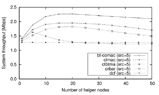
Fig. 8 shows the comparative results of the system throughput of the BT-COMAC scheme proposed in this paper, the cross-layer MAC scheme proposed in [6] (referred to as‘CLMAC’), the CTBTMA scheme proposed in [5], and the CRBAR scheme proposed in [7]. According to the performance evaluation results, the BT-COMAC scheme proposed in this paper shows an approximately 15% improvement in system throughput as compared to the cross-layer MAC scheme [6] that previously had the best performance. The BT-COMAC scheme has the best performance results because the well-processed helper node selection competition using the received power strength and a direct competition using an RTH frame, rather than a busy signal, results in reduced overheads. Further, the CTBTMA scheme has good system throughput performance when the number of helper nodes is small, for instance, less than 10.
However, as the number of helper nodes becomes greater than 10, the system throughput tends to decrease abruptly, as this scheme cannot select one helper node when there is more than one candidate helper node with the same utility value.
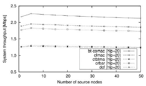
Fig. 9 shows a comparison of the system throughputs of the BT-COMAC scheme according to changes in the number of source nodes, with those of three cooperative MAC schemes and the DCF scheme when the number of helper nodes is 20. According to the results, the BT-COMAC scheme has the best system throughput performance among the five different schemes. The system throughput of the CTBTMA scheme is as large as the traditional DCF scheme because the CTBTMA scheme has difficulty in choosing one appropriate helper node among 20 candidate helper nodes, some of which may have the same utility value.
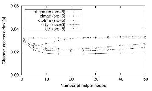
Fig. 10 shows a comparison of the channel access delay performance of the BT-COMAC scheme according to changes in the number of helper nodes, with that of three cooperative MAC schemes and the DCF scheme when the number of source nodes is 5. This result has the appearance of the system throughput performance (presented in Fig. 8) flipped upside down because channel access delay has an inverse relationship to system throughput. Fig. 10 shows that BT-COMAC has the best channel access delay performance among the five different MAC schemes.
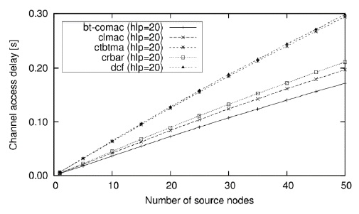
Fig. 11 shows a comparison of the channel access delay performance of the BT-COMAC scheme according to changes in the number of source nodes, with that of three cooperative MAC schemes and the DCF scheme when the number of helper nodes is 20. Fig. 11 shows that the BT-COMAC scheme has the best channel access delay performance among the five different MAC schemes.
In this paper, we proposed a novel cooperative MAC protocol, including a scheme for the selection of a helper node, in order to utilize cooperative diversity. This new cooperative MAC protocol used the received power strength when choosing an appropriate helper node for cooperative communication. The saturated traffic model and a slow fading wireless channel model were used for traffic and channel modeling, respectively. We then conducted a performance evaluation by using a computer simulation. System throughput and channel access delay time were used as the performance measures. Numerical results showed that the system throughput performance of the proposed BT-COMAC protocol improved by approximately 15% when compared with the cooperative MAC protocol [6] that previously had the best performance. In future research, the scheme proposed in this paper will be expanded to an environment where multiple helper nodes can be supported.