The success of the film Avatar in 2009 and the remarkable advances in digital broadcasting technology during recent years have changed the movie industry; in addition, these advances have shown that the three-dimensional (3D) industry, whose profitability has been questioned, can be a new driving force in the market. Furthermore, the 3D industry has been recognized as a next-generation growth engine that can lead the Korean economy. Broadcasters are increasingly promoting the 3D industry; e.g., the digital satellite broadcasting service Skylife began 3D channel broadcasting for the first time in 2013; this was followed by terrestrial broadcasting transmissions [1,2].
Because 3D data contain more information and higher added value than two-dimensional (2D) data, we need to develop copyright and security solutions for 3D content before 3D data become more universally available, which they are not currently. The additional information contained in 3D data, such as depth and stereoscopic images, makes it necessary to protect 3D content information and security as well as recognize 3D-related information. Thus, it is important to provide protection and security solutions according to the characteristics of 3D data. Recently, digital watermarking and content encryption have been studied widely for protecting image and video information. Watermarking is a technology used for authenticating copyright ownership to determine the real owners if illegal contents or theft is suspected. A watermark is not visible when the image or video is displayed, but it is robust against attacks to remove or modify it in images or video contents.
Because of the increase in the popularity of 3D stereoscopic images, several studies have investigated the protection of stereo images [2-5]. Thus, we provide a brief review of the related studies in this area. Kim et al. [2] applied a dual-tree complex wavelet transform and selected sub-bands that are less sensitive to viewpoint changes after transformation by considering the characteristics of depth-image-based rendering (DIBR), which was followed by watermarking based on the quantization results. To combat various attacks, Kim et al. [3] applied a discrete cosine transform (DCT) to regions that changed rarely by using the scale-invariant feature transform and inserted a watermark with a spread spectrum technique based on the coefficients. Wang et al. [4] proposed a watermark insertion method in frontal views by using depth information to avoid damaging the inserted watermarks in arbitrary images created using DIBR, where transformed sub-bands with less sensitivity to viewpoint changes were used to insert the watermark. Lee et al. [5] proposed a method for finding the viewpoint image most similar to an arbitrary viewpoint by using normalized cross-correlation (NCC), before applying the same watermarking methods as those currently used for 2D images.
Watermarking is a digital content copyright protection technique for preventing the illegal copying of multimedia and for protecting the copyright. Digital watermarking can be divided into watermark generation, insertion, and extraction. Assuming that

Invisibility and robustness should be considered during watermarking. Invisibility means that the digital watermark should be inserted without degrading the quality of the original content and robustness means that the inserted watermark should be resistant to malicious or non-malicious attacks.
>
B. Creation of Intermediate Viewpoint Images
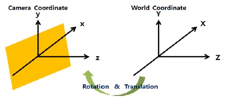
In the proposed method, intermediate viewpoint images are generated using DIBR. In the DIBR method, a texture image at a reference viewpoint is transformed into real-world coordinates by using intrinsic and extrinsic parameters obtained from the camera and depth information, before re-projecting the transformed image into 2D space by using the camera parameters at a virtual viewpoint, thereby transforming the image into the image coordinates at the preferred viewpoint. The real-world and camera coordinates are both 3D coordinates, and the transformation between the two systems of coordinates can be achieved by using rotation and translation operations, as shown in Fig. 1 [6].
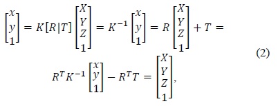
Eq. (2) describes the process used to calculate the 3D coordinates based on the camera parameters and image coordinate values:


where (
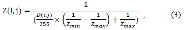
Eq. (3) calculates
To generate virtual viewpoints, the internal and external camera parameters should be defined at the virtual viewpoint locations. In general, the internal parameters are determined by the internal structure of the camera, whereas the external parameters are used because they can be transformed into locations at virtual viewpoints.
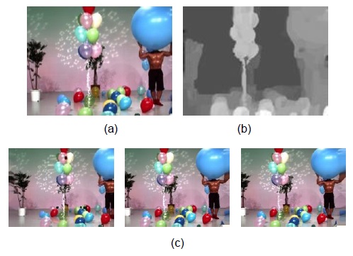
Fig. 2 shows multi-viewpoint images generated from the corresponding texture and depth images.
>
C. Proposed Watermarking Method
1) Watermark Insertion
Fig. 3 shows the watermark insertion algorithm. First, the reference viewpoint image is moved right and left in the depth map until the maximum viewpoint change is obtained, as described in [7], and the regions that are likely to disappear due to DIBR are detected by overlapping them.
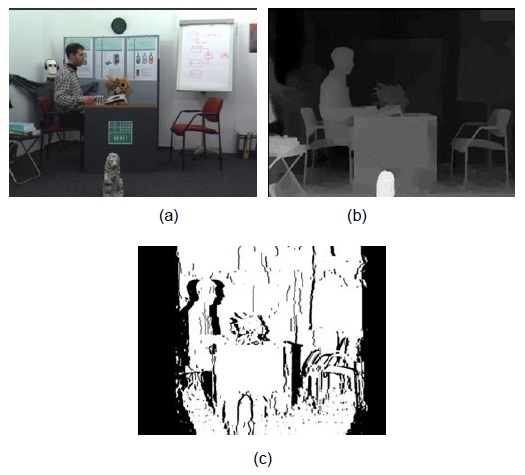
Fig. 4 shows an example of the regions generated by DIBR. Fig. 4(a) shows a texture image, and Fig. 4(b) shows a depth image. Fig. 4(c) shows a retained region (white) and a non-retained region (black) after overlapping the stereo images in the right and left viewpoints by DIBR, respectively.
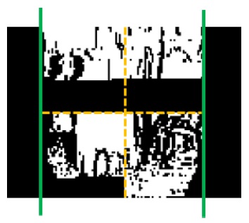
Next, the remaining part that contains the non-occluded region on the right and left sides is divided into four subparts. Four sub-regions are generated, and scanning is performed with the same block size,
For the selected block, a watermark is embedded in regions with intermediate frequency.
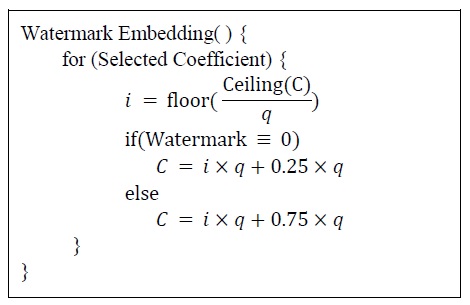
Fig. 6 shows how the watermarks are embedded. The process shown in Fig. 6 is a quantization process. Ceiling()/floor() is a function used to determine the closest large/small integer and q refers to the level of quantization. C denotes a coefficient that represents where the watermark is embedded.
2) Method for Viewpoint Restoration
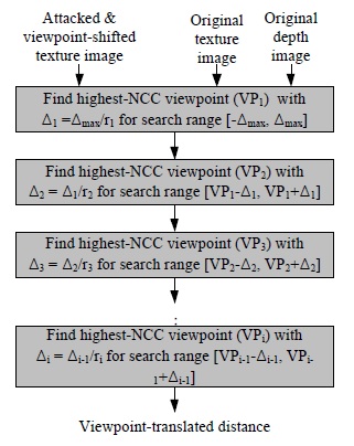
To extract a watermark, NCC is used to find an image with the most similar viewpoint after viewpoint image changes with respect to arbitrary viewpoints [7]. A relative value is used to find the viewpoints of images after they change to an arbitrary viewpoint based on the NCC value. Therefore, the absolute operation cannot find the viewpoint. Fig. 7 shows the viewpoint trace method using the NCC value. After finding the changed viewpoint, the reverse-viewpoint change is performed from the found viewpoint to the reference viewpoint.
Thus, a changed viewpoint is found by the viewpoint trace and the reverse viewpoint change is performed for the reference viewpoint by using the found viewpoint.
Because the images change according to the viewpoints selected by the user when the viewpoint is generated, the proposed method aims to find regions at an arbitrary viewpoint by using a depth map (non-blind watermarking) when extracting watermarks.
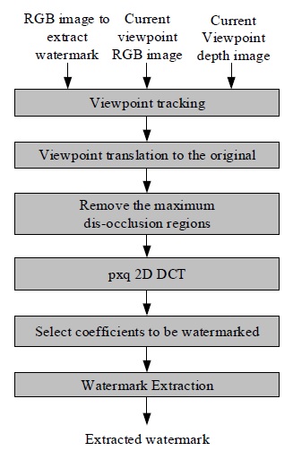
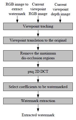
3) Watermark Extraction
The watermark extraction process is similar to the watermark insertion process.
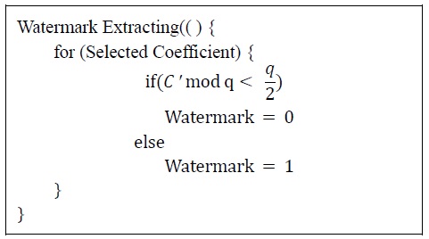
Fig. 8 shows the watermark extraction process, where the viewpoint is restored initially by using NCC, as described in [7]. Next, the watermark-embedded region is found and the watermark is extracted in the same manner as the insertion process. Fig. 9 shows the watermark extraction algorithm, in which the quantization size q plays an important role. As the value of q increases, the size of the quantization region also increases, thereby making the watermark more robust. Thus, the robustness of the watermarking algorithm can be controlled by the size of
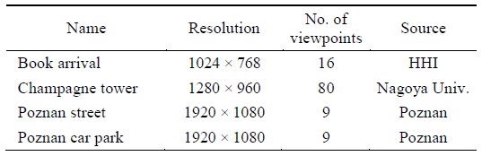
In this section, we describe the experimental results obtained using the proposed algorithm based on several images. Table 1 describes the images used in the experiment and their sources.
[Table 1.] Images used in the experiments

Images used in the experiments
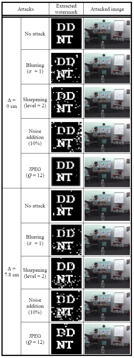
The insertion and extraction algorithms shown in Figs. 3 and 8 were tested before and after viewpoint changes. JPEG compression, blurring, sharpening, and salt-pepper noise attacks were applied to the images. The compression attack was performed before changing the viewpoint. The blurring and sharpening attacks were applied after changing the viewpoint on the basis of the actual conditions. JPEG compression used quality = 0 as the highest compression rate (12-point scale). The blurring and sharpening attacks were performed until the effect of the attack was visible in the image. The salt-pepper noise attack was applied to 10% of the overall image.
Table 2 shows the average experimental results for all of the images. After the viewpoint changed, only images that moved 7.8 cm to the right-hand side were usually seen, which corresponded to about 5% of the baseline distance (the ratio of the change in the viewpoint distance with respect to the width of the image) [2-4].
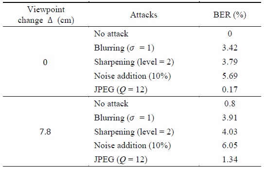
Average bit error rates (BERs) obtained in the experiments using the proposed method (5% viewpoint translation)
In Table 2, although viewpoint restoration was performed using NCC after the viewpoint changed, the bit error rate (BER) was somewhat higher than that without the viewpoint change. This is because non-occluded regions and occluded regions (regions that can be seen from the reference viewpoint, but which become invisible after the viewpoint changes) can be generated during viewpoint changes despite the restoration of the viewpoint. Thus, parts of the image that were present in the reference image could disappear, or parts of the image that were not present in the reference image could appear, which prevented the same watermark from being extracted at the reference viewpoint.
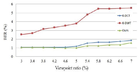
Fig. 10 shows the watermark extraction results before and after changing the viewpoint in one of the images described in Table 2. Fig. 11 compares the results obtained using the proposed method and the other methods described in previous studies, i.e., K-DCT refers to a method that uses 2D DCT [7] and K-DWT is a method that employs
2D DWT, while ‘Ours’ refers to the method proposed in the present paper. The reference line distance was set to that used in [4] and [5] for the three viewpoint changes shown in Fig. 11. The two methods proposed by Lin were set to 5% for the translated viewpoint as the reference image on the right-hand side.
Both the methods proposed by Seo et al. [7] and the proposed method increased the BER as the viewpoint moved. However, the proposed method obtained a lower overall BER than the two methods proposed by Seo et al. [7]. Thus, the proposed method was more robust against viewpoint translation.
In this study, we proposed a watermarking method for protecting the ownership of stereo and multiview images, where watermarks could be generated at arbitrary viewpoints by using depth data related to the target image and the texture image. In the proposed method, 3D warping was used to preserve the watermarks via DIBR, before selecting a region that would not disappear during the DIBR process because of overlapping regions. The selected region was then divided into four sub-regions to select regions that would not disappear again, before embedding the watermarks by 2D DCT. The embedded watermarks were invisible, and we verified their robustness; i.e., the error rate was 1.2%, whereas the existing methods had an average error rate of 3.2%.