In the near future, wireless communication systems will operate in the very high-frequency range such as the Wband (75–110 GHz) because most available microwave bands for commercial applications have already been exhausted. To realize various W-band applications [1-3], the antenna is one of the most critical components. The success of W-band applications depends on the integration of electronic and photonic components with antennas. A highperformance antenna can relax system requirements and improve the overall system performance.
In the case of a single-element antenna, the radiation pattern is usually broad and the directivity is low. These problems can be solved by enlarging the size of the radiating element or by assembling the radiating elements in a geometrical configuration, known as an array. Antenna arrays can be used to increase the overall gain, provide diversity reception, cancel out interference from a particular set of directions, and steer the array so that it is most sensitive in a particular direction. These arrays are attractive because of their light weight and the simple integration with other active devices.
In this work, we develop a compact, high-efficiency phased array antenna focused on the performance improvement of the directivity and wideband by using the log-periodic antenna (LPA). This antenna was fabricated using the microwave monolithic integrated circuit (MMIC) technology on a GaAs substrate; therefore, the antenna and the active components could be integrated on the same substrate.
II. W-BAND 1×4 PHASED ARRAY ANTENNA
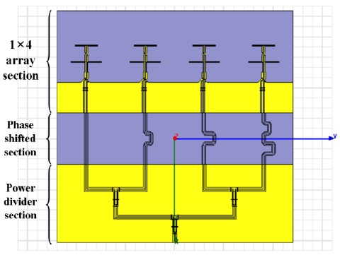
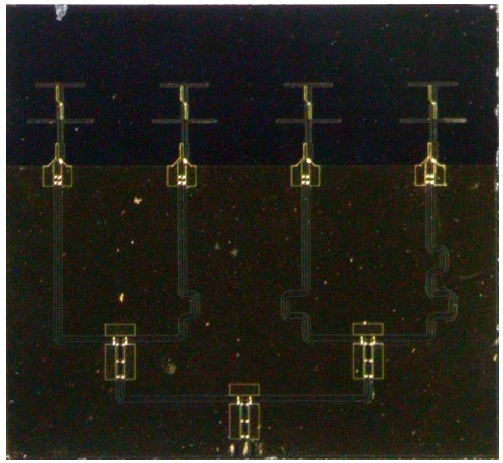
The configuration of the designed W-band phased array planar antenna is shown in Fig. 1. In advance of the development of the PAA, we designed a LPA as a singleelement antenna.
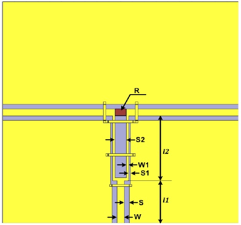
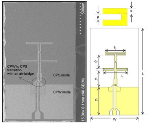
The LPA comprises two folded dipoles: crisscross connections connecting the adjacent folded dipole and a coplanar waveguide (CPW) feeding line. In order to excite the dipole array with a balanced mode, we used a transition with an air-bridge structure from the CPW mode to the coplanar stripline (CPS) mode, as shown in Fig. 2. The leftside ground of CPW is combined with the right-side ground at the terminal of the air bridge to form the CPS. The propagated signal will change 180° in phase after transmitting through a crisscross connection.
The mechanical phase reversal between dipoles produces a phase progression so that the signal is end-fired in the direction of the shorter dipole while the ground plays the role of a reflector. The geometrical parameters of the designed LPA are shown in Table 1. The antenna parameters were designed at a center frequency of 94 GHz and optimized using an electromagnetic simulation tool, Ansoft HFSS. The measurement results show that the fabricated LPA has a wide bandwidth of 26 GHz and a low peak gain of 4.43 dBi at 94 GHz.
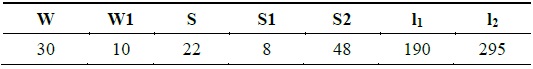
[Table 1.] Parameters of the designed 94-GHz log-periodic antenna (unit: μm)
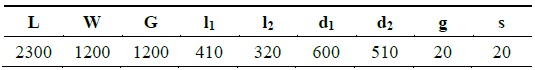
Parameters of the designed 94-GHz log-periodic antenna (unit: μm)
>
B. Power Divider and Phase Shifter
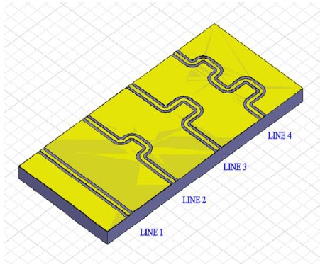
The power divider is a fundamental and important component widely used in feeding networks in antenna arrays. Each array utilizes simple corporate feeding with a uniplanar CPW Wilkinson power divider [4]. Figs. 3 and 4 show the physical configurations of the uniplanar power divider and the 45° phase shifter section, respectively. The power divider consists of a quarter-wavelength section of a coupled CPW, which has a characteristic impedance of 50 a resistor of R = 100 Ω, a CPW input port, and two CPW output ports with a characteristic impedance of 50 Ω. The input signal fed to port 1 can be divided into two components that arrive in-phase at port 2 and port 3, respectively. The relevant geometrical parameters of the designed Wilkinson power divider are listed in Table 2. A phase shifter can be made by bending the CPW line by about 1/8th the wavelength to get a 45° phase shift.
[Table 2.] Optimal parameters of the designed Wilkinson power divider (unit: μm)

Optimal parameters of the designed Wilkinson power divider (unit: μm)
>
C. Phased Array Antenna Fabrication
The designed phased array antenna was fabricated by using Millimeter-wave Innovation Technology Research Center (MINT) standard MMIC processes. The fabrication process for the phased array antenna was carried out in the following sequence: first, the metals Ti/Au (70/700 nm) were evaporated, and then, the rear portion of the GaAs substrate was thinned from an original thickness of 680 µm to the final thickness of 100 µm. After the rear side was metalized, the air-bridge process was performed to avoid the intersection between two branches of the cross and to connect the grounds at the front [5].
The fabricated phased array antenna can be integrated with active devices on the same GaAs substrate because it is fabricated using the standard MMIC process. Fig. 5 shows a secondary electron microscope photograph of the fabricated phased array antenna. The total chip size is 4.8 mm × 4.5 mm.
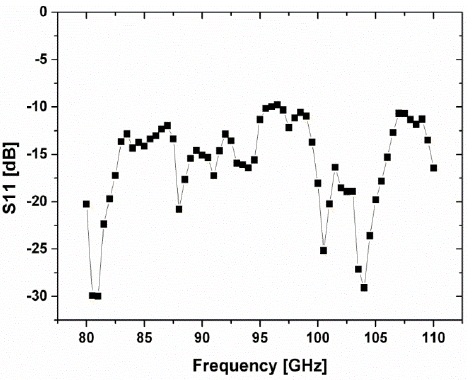
The scattering parameters of the fabricated LPA were measured on-wafer by using an Anritsu ME7808 broadband vector network analyzer. The measurement results of the return loss are shown in Fig. 6. This antenna operates in a wide frequency range from 80 GHz to 100 GHz with a return loss better than -10 dB. The measured return loss agrees well with the simulated one. The antenna gain versus frequency is shown in Fig. 6. At 94 GHz, it has a return loss of -16 dB and a gain of 4.43 dBi.
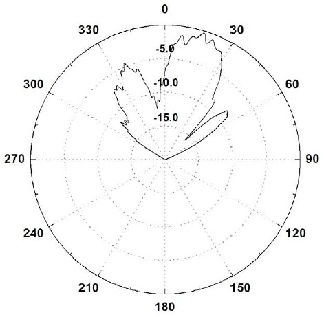
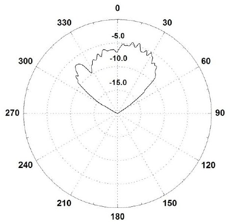
The measurement results of the radiation patterns are shown in Figs. 7 and 8. The radiation patterns were measured at the Korea Radio Promotion Agency.
In this work, the GaAs substrate is thinned in order to reduce the surface wave effect in a high-permittivity substrate, which can severely corrupt the performance of the printed antenna. Furthermore, because of the process compatibility with the active devices, we are convinced that the fabricated LPA can be integrated in a single front-end chip and applied in many applications at the W-band frequency, such as a transceiver and a sensing element.
We developed a 94-GHz PAA with a phase shifter and a Wilkinson power divider on a GaAs substrate. This antenna was fabricated using the MMIC technology for unipolar circuit implementations. The fabricated antenna showed a wide bandwidth from 80 GHz to 110 GHz with a return loss better than -10 dB. At the center frequency of 94 GHz, the fabricated phased array antenna showed a return loss of -16 dB and a gain of 4.43 dBi. The developed antenna is expected to be widely applied in many applications at the W-band frequency.