This paper proposes an RGB to RGBY color conversion algorithm for liquid crystal display (LCD) using RGW pixel structure with two-field (yellow and blue) sequential driving method. The proposed algorithm preserves the hue and saturation of the original color by maintaining the RGB ratio, and it increases the luminance. The performance of the proposed RGBY conversion algorithm is verified using the MATLAB simulation with 24 images of Kodak lossless true color image suite. The simulation results of average color difference CIEDE2000 (ΔE*00) and scaling factor are 0.99 and 1.89, respectively. These results indicate that the average brightness is increased 1.89 times compared to LCD using conventional RGB pixel structure, without increasing the power consumption and degrading the image quality.
A liquid crystal display (LCD) is most widely used in various applications such as mobile phones, tablets, monitors, televisions and public information displays due to the characteristics of high resolution, thinness and large size of the panel. Nowadays, achieving high brightness along with low-power consumption is one of the major issues of LCDs. The brightness of the LCD is closely correlated with the luminance of the backlight (BLU) and the transmittance of the panel [1-3]. The easiest way to increase the brightness of the LCD is to increase the BLU luminance, but this causes an increase of power consumption. Therefore, a method to reduce the power consumption of the LCD is required along with maintaining the high-brightness and without degrading the image quality.
The conventional thin film transistor LCD (TFT-LCD) has employed red (R), green (G) and blue (B) color filters (CFs) to represent a color. However, the optical loss is considerable because CFs only transmit light in accordance with the wavelength of their own colors, and they block other colors. To reduce the power consumption due to CFs, the method using RGB and white (W) sub-pixel structure has been proposed and widely used [4-8]. This method adds a W sub-pixel to not only improve the transmittance of TFT-LCDs, but also to reduce the power consumption under the condition having the same brightness. However, during the reproduction the saturated colors, such as R, G, B, and yellow (Y), are perceived darker because the transmittance of the RGB sub-pixel is decreased while that of the W sub-pixel is increased, which causes the simultaneous contrast problem [5, 9]. Especially, yellowish-green color looks much dimmer than other colors due to the spectral sensitivity of the human eye [10]. In addition to the RGBW display, various kinds of multi-primary color LCDs have been investigated by a lot of display manufacturers to increase the transmittance and color reproducibility of the panel. Especially, the display technology using RGBY primary color has been presented in several papers [11-15] and commercialized [16]. Most of RGBY LCDs [11-14, 16] use RGBY CF with W LED BLU and operate like conventional TFT-LCD. Whereas, a hybrid driving method using RGW sub-pixel structure with two-field (Y and B) sequential driving method [15] consists of a panel using RGW pixel and a BLU using Y and B light sources (YB-BLU), and has two driving periods according to the selected light source color of the BLU. The Y light source is made of yellow phosphor coated on the B LED, and the B light source uses the B LED. The Y light source has broad spectrum characteristics across the R and G spectrum. In the first driving period, the Y light source in YB-BLU and all pixels in the panel are turned on, and thereby R, G, and Y colors are represented on the panel. In the second driving period, B light source and W sub-pixels are turned on, and then only the B color is represented on the panel. The generated R, G, and Y colors in the first driving period and B color in the second driving period are mixed and seen as just one color by faster driving than the temporal resolution of the human eye. The hybrid driving method is operated like RGBY LCD because the W sub-pixel is operated like Y and B sub-pixels. The RGBY LCDs increase not only the brightness of the achromatic color but also the brightness of Y and B colors, and thereby a simultaneous contrast problem is alleviated. However, in order to use the RGBY LCD, an RGB to RGBY image signal conversion algorithm is required because most host-systems generate the image data using RGB color signals.
In this paper, we propose an RGB to RGBY image signal conversion algorithm for LCDs using RGW pixel structure with YB field sequential driving method. In Section II, an RGB to RGBY color conversion algorithm is described with its flowchart and data mapping example. In Section III, the proposed RGBY conversion algorithm is simulated using MATLAB and compared with the previously proposed RGBY conversion algorithm. The image quality and brightness are verified using the color difference CIEDE2000 (ΔE*00) [17] and brightness gain factor, respectively. Finally, conclusions are given in Section IV.
II. ALGORITHM FOR RGB TO RGBY COLOR CONVERSION
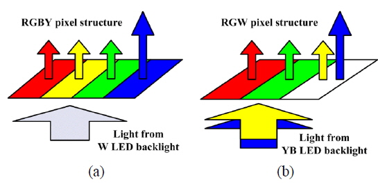
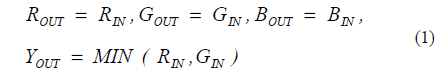
Figure 1 shows the pixel structure and operation principle of the RGBY LCD in [14, 15]. Due to the added Y, the luminance of B should be increased to maintain the white balance of the LCD. In Fig. 1 (a), the luminance of B sub-pixel is increased by controlling the illuminant spectrum of the BLU. In order to do this, the spectrum near to B of the BLU is increased and others are slightly decreased. On the other hand, in Fig. 1 (b), the luminance of B is doubled by increasing the luminance of the B LED in YB-BLU to maintain the white balance of the LCD. In addition, the LCD using RGBY requires an RGB to RGBY data conversion algorithm to display the image, and thereby most of display manufacturers have their own proprietary algorithms to improve the brightness and image quality. An RGB to RGBY conversion algorithm [14] is given by

where RIN, GIN, and BIN are the input image data from the host system, and ROUT, GOUT, BOUT, and YOUT are the output data for display images, and MIN(RIN, GIN) is the minimum value of RG input data.
The LCD with RGW pixel has the extended color space with the W sub-pixel using YB-BLU. In the Y field driving period, the extended color space on the RG space is diagonally extended by the luminance of RG sub-pixels and W sub-pixel. In the B field driving period, the blue color is determined by the W sub-pixel and the luminance of the B LED.
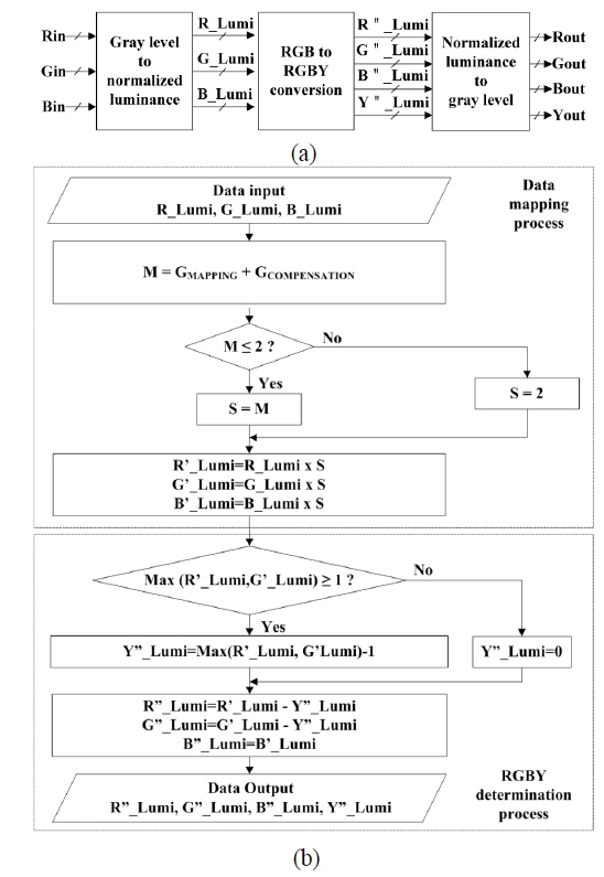
Figure 2 shows the proposed color conversion process from RGB to RGBY. As shown in Fig. 2 (a), the RGB data signals are converted to the normalized luminance at first, and then RGB to RGBY conversion is performed in a luminance space; the process of RGB to RGBY conversion should consider that the gray level data of RGB provided from the host system are linear, whereas the luminance levels of the displayed image on the LCD are non-linear according to the characteristics of the human eye. After completing the conversion, the calculated luminance levels of RGBY are converted to the gray level for displaying the input data.
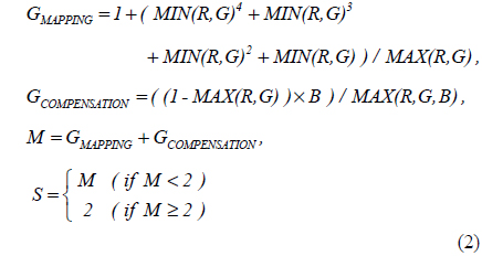
The proposed conversion algorithm is designed to increase the brightness without color distortion by preserving the hue and saturation of original image data. It consists of a data mapping process on the extended color space, and RGBY determination process as shown in Fig. 2(b). The data mapping process is performed by multiplying the scaling (S) factor by the luminance of input RGB data. The S factor is calculated using the data mapping gain parameter (GMAPPING) on RG color space and an additional RG luminance gain parameter (GCOMPENSATION). GMAPPING is a mapping function that maps the input data to the extended color space, and increases the luminance of most input data except the colors near pure RG. To increase the luminance of the colors near pure RG which has the intermediate gray level, GCOMPENSATION is additionally employed. Using the non-linear histogram modification method [18], the luminance of the near pure RG color having intermediate gray level can be increased according to B. The total luminance gain is calculated by summing GMAPPING and GCOMPENSATION, but limited by 2 because the maximum luminance using the RGY sub-pixel is twice larger than the luminance using the RG sub-pixel. Accordingly, the S factor varies in 1 ≤ S ≤ 2 and is determined by the following equations

where S, M, MIN(R,G) and MAX(R,G), MAX(R,G,B), and B are S factor, total luminance gain, minimum and maximum values of R and G, and the maximum value of R, G, and B, and B color luminance, respectively. The calculated S factor is applied to RGB colors to preserve the hue and saturation, and the calculated results of data mapping process R’, G’, and B’ are determined by the following equations.

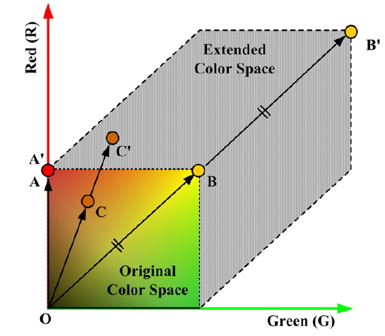
Figure 3 shows the data mapping example of RG color space using the proposed conversion algorithm. The original A, B, and C colors are represented by the luminance of R and G sub-pixels, and scaled by the S factor, and then mapped to A’, B’, and C’ colors, respectively. The color on the R or G axis is not scaled because of S=1. The colors near the line OB’ are scaled by S=2. Other colors between the line OB’ and the RG axis have the intermediate value of S, ranging from 1 to 2.
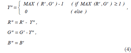
After the data mapping process, the RGBY determination process is performed and the luminance of RGBY is calculated using the luminance of RGB received from the data mapping process. In the LCD system using the RGW sub-pixel with the YB field sequential driving method, the RGY and B fields are sequentially driven to represent the color image, and this may cause the image distortion such as a color mixing artifact due to the slow response of the liquid crystal. To prevent the above problem, the RGBY determination process minimizes the usage of the W sub-pixel as in the following equations.
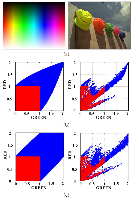
The performances of the conversion algorithm of the proposed RGBY conversion algorithm and the conversion algorithm using equation (1) are evaluated using the MATLAB simulation. With two images of color picker and hats, the simulation of the data mapping process is performed to verify the usage of the extended color space on RG color space and the luminance scaling.
In Fig. 4, the RG data of original images and the simulation result of the proposed data mapping process are depicted in red and blue dots, respectively. As shown in Fig. 4 (b), the simulation results using the RGB to RGBY conversion algorithm using equation (1) reflect that the extended color space is used in the partial area and the S factor of reddish and greenish colors is smaller than the proposed algorithm. On the other hand, as shown in Fig. 4 (c) the simulation results using the proposed RGB to RGBY conversion algorithm describe that the proposed data mapping covers most of the area of the extended color space. Using the proposed algorithm, the luminance of yellow color is scaled up to twice and the luminance of reddish and greenish colors is scaled by the S factor between 1 and 2. These results explain that the image using the proposed algorithm is brighter than that using the conversion algorithm using equation (1) and look similar to the original one.
With 24 images of Kodak lossless true color image suite [19], the simulation of the proposed RGBY conversion algorithm and the conversion algorithm using equation (1) is performed.
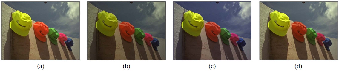
Figure 5 and Fig. 6 show the original images used for the simulation and examples of the simulated images using the proposed conversion algorithm, respectively. As shown in Fig. 6, RGW sub-pixel structure with YB field sequential driving using the proposed RGBY color conversion algorithm looks brighter than other LCD using conventional RGB sub-pixel and RGBY sub-pixel structure using equation (1), and is very similar to the original image. Using the ΔE*00 and S factors, the performance of the proposed RGBY conversion algorithm is compared with that of the RGBY conversion algorithm using equation (1). The ΔE*00, which represents the color difference related to the lightness, hue, and chroma, is widely used due to the similarity to the human visual system [20]. The S factor, which represents the degree of brightness increment, is inversely proportional to the power consumption of the LCD under the similar brightness using RGB sub-pixels.
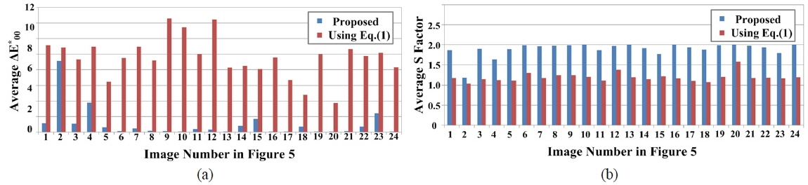
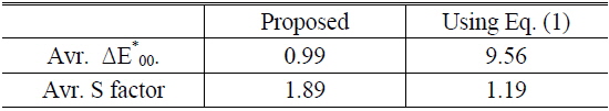
Figure 7 shows the average ΔE*00 and average S factors of the simulated images with the proposed RGBY color conversion algorithm and the RGBY color conversion algorithm using equation (1). The simulation results show that the proposed RGBY color conversion algorithm has lower ΔE*00 and higher S factor in all 24 images compared to the RGBY color conversion algorithm using equation (1). The proposed RGBY color conversion algorithm has the maximum and average ΔE*00 of 9.03 and 0.99, and the maximum and average S factor of 2.00 and 1.89, respectively. On the other hand, the RGBY color conversion algorithm using equation (1) has the maximum and average ΔE*00 of 14.61 and 9.56, and the maximum and average S factor of 1.58 and 1.19, respectively. The conversion algorithm using equation (1) does not cause the color distortion in representing the achromatic color, but causes the color distortion in representing the combined color of one of RG and B, such as cyan or magenta. The hue and saturation of the combined color are changed because the ratio of RGB is changed from 1:1:1 to 1:1:2. Accordingly, this causes ΔE*00 to become larger and the combined color is perceived more bluish than the original one, as shown in Fig. 6. Moreover, the conversion algorithm using equation (1) uses the partial area of the extended color space, whereas the proposed conversion algorithm uses most of the area of the extended color space as shown in Fig. 4, and thereby the proposed algorithm can have larger S factor of the reddish and greenish colors than the algorithm using equation (1). As summarized in Table 1, these results show that the proposed RGB to RGBY conversion algorithm can achieve 59% higher brightness with invisible image distortion compared to the LCD using RGBY sub-pixel structure using equation (1). Furthermore, these results indicate that 1.89 times higher brightness can be achieved compared to the conventional LCD using RGB sub-pixel.
[TABLE 1.] Simulation Results of ΔE*00 and S factors

Simulation Results of ΔE*00 and S factors
An RGB to RGBY color conversion algorithm for an LCD using RGW pixel structure with a YB field sequential driving method is proposed. The RGB to RGBY conversion algorithm is important to reproduce because the algorithm determines brightness and image quality of the displayed image. The performance of the proposed conversion algorithm is verified using the MATLAB simulation with 24 images of Kodak lossless true color image suite. The simulation results of average ΔE*00 and S factor are 0.99 and 1.89, respectively. These results indicate that the average brightness is increased 1.89 times without increasing the power consumption compared to the LCD using RGB sub-pixels and the simultaneous contrast problem is alleviated. Therefore, the proposed RGBY conversion algorithm is suitable for the high brightness and low power consumption LCD using RGW pixel structure with YB field sequential driving method.

![Pixel structure and operation principle of RGBY LCD using (a) RGBY CF [14] and (b) RGW sub-pixels with YB field sequential driving method [15].](http://oak.go.kr/repository/journal/16152/E1OSAB_2014_v18n6_777_f001.jpg)


![Images of Kodak lossless true color image suite [19].](http://oak.go.kr/repository/journal/16152/E1OSAB_2014_v18n6_777_f005.jpg)