Projection display is commonly used for a large display system in many places such as conference rooms or movie theaters because the system can be composed of a relatively simple structure. Although the projection display can easily present a large scene with a wide viewing area, the system should include sufficient space to enlarge the projection image. Since the projection system is based on light ray propagation, the projection rays can be shaded by an object located on the path of the rays. To solve the occlusion problem, a wedge projection system has been proposed [1-5]. The wedge projection system can resolve the occlusion problem of the light rays and present the large scene on the screen within a narrow space. The wedge projection system can use small space effectively by compressing the light rays into a thin waveguide which is made of acrylic or glass.
However, since the wedge projection system is based on total internal reflection, an imaging problem called the dark zone occurs when the incident rays have an unconformable initial angle and position at the aperture of wedge, which degrades the image quality critically. To resolve the dark zone problem, some methods have been proposed and reported [6, 7]. In previous works [8, 9], we also proposed a ray retracing method to prevent the dark zone problem. By the ray retracing method, we can obtain the projection condition of the rays at the aperture to avoid the dark zone.
The projection image of the wedge projection system can be enlarged by adding the slab structure to the aperture of the wedge. The slab structure extends the optical path length of the projection rays before the rays reach the inclined surface of the wedge. The ray retracing method can be applied to the wedge-only system without the slab structure. As the optical paths of the rays are changed when the rays are reflected in the slab structure and escape from it, the incidence angle of the rays at the aperture of the wedge should be changed. The difference of the incidence angle at the aperture produces different image formation on the inclined surface. As a result, the image on the slope is distorted and presented with the dark zone problem.
In this paper, we analyze the image formation of the projection rays through the slab structure to investigate the dark zone phenomenon caused by the length and the thickness for the enlarged projection area, and we propose a design method to make a wedge projection system with a slab structure which does not produce the dark zone. Furthermore, we propose the split imaging region method to setup a thinner and wider wedge projection system. The simulation and the basic experiments to prove the feasibilities of the proposed methods are performed and presented in this paper.
The slab structure can enlarge the projection image by extending the optical path length of the projection rays in the waveguide. The slab structure attached to the wedge guides the projection rays by total internal reflection and the light rays arrive at the aperture of the wedge structure. For the previous design method, the wedge-only structure is assumed. The projection rays reflected at the boundary between the wedge and the slab structure should be defocused, which could produce imaging problems. To resolve the boundary problem, the advanced design method for the wedge system with the slab structure needs to consider the effect at the boundary.
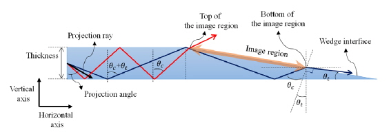
To project the image on the inclined surface of the wedge waveguide including the slab structure without the dark zone, the distribution angle of the rays is limited to narrower than the taper angle, which is the slope angle of the wedge. To analyze each projection ray which makes a continuous image without the dark zone on the inclined surface, we can find that the angle distribution between the rays which reach the top and the bottom of the imaging region should equal the taper angle

where
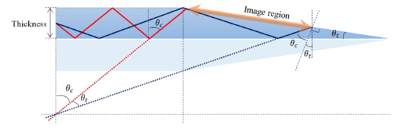
For the wedge system with the slab structure, the projection condition should be determined under consideration of the reflection in the slab structure. The two rays which arrive at the inclined surface are assumed to represent the image after reflection at the bottom side of the wedge, of which one is for the top of the imaging region and the other is for the bottom. The ray which reaches the corner of the boundary between the wedge and the slab structure creates a discontinuity in the image after the reflection. To prevent the discontinuity of image at the wedge, the rays should not go through the corner and the specification of the structure is designed under consideration of that boundary condition. The bundle of rays which is reflected at the bottom side of the waveguide should follow the path for which the width is twice the thickness of the wedge structure according to the stack-up method, which traces the path of the ray propagation in the waveguide by stacking up the same structure with total number of layers equal to the number of reflections as shown in Fig. 2 [10]. The path of the rays in the slab structure should be retraced as if there were no reflection problem at the boundary, which can be a design role of the distribution angle and the location of the reflection for the enlarged image in the inclined surface of the wedge through the slab structure without the dark zone. Based on the analysis of the location and the angle restriction of the rays, we can obtain the length of the imaging region on the inclined surface and the required length of the slab structure. First, the ray that reaches the top of the imaging region is retraced using the stack-up method. Second, the ray which attains the bottom of the imaging region is retraced using the condition that the ray should reflect at the point very nearby the boundary between the wedge and the slab structure. Also, the bundle of rays should follow the path for which width is twice the waveguide thickness.
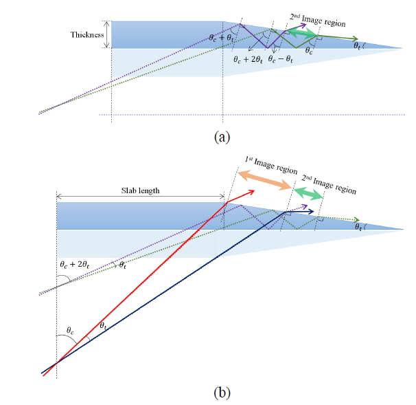
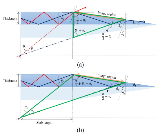
The rays between two outer rays for which angles are between the critical angle and the sum of the critical angle and the taper angle can reach the inclined surface and form an image on it. Since these rays satisfy the condition, we do not need to consider the angle distribution problem after the reflection at the boundary between wedge and slab structures. We can obtain the length of the imaging region to calculate the trigonometric function to the virtual triangle made with the paths of the two outer rays and the interface of the wedge structure as shown in Fig. 3 (a).

where
By extending the path of the two rays to the convergence point, we can obtain the length of the slab structure required to project the calculated imaging region. When the two reflected rays in the slab structure are retraced by the stack-up method, the rays should converge at a point. Applying the trigonometric function to the triangle which is made by the paths of the two outer rays and the imaging region, we can obtain the required slab length as shown in Fig. 3 (b).
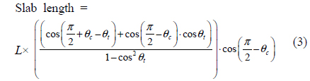
where
The number of reflection in the slab structure and the initial projection angle can be obtained from the retraced rays. The tangential value of retraced rays divided by the slab thickness yields the reflection number in the slab structure. The initial projection angle is inverted depending on whether the number is odd or even. By this process, we can design the slab structure and the projection system to represent the enlarged image on the inclined surface of the wedge without producing the dark zone.
Additionally, the slab structure needs an angled entrance aperture called the input prism to reduce the key stone distortion of the projection image. The angle can be determined as the supplementary angle of the projection angle.
III. SPLIT IMAGING REGION METHOD AND SIMULATION
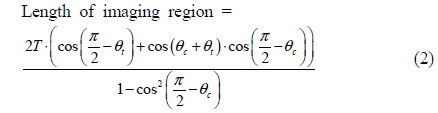
According to Eq. (2), the length of the imaging region is a function of the taper angle and the thickness of the slab structure, which means that the length of the imaging region is proportional to the taper angle. However, if the wedge structure is thicker, the volume of the whole system becomes bulkier and the effectiveness of the space utilization is degraded. Therefore, to represent a large scene on the inclined surface of a wedge with thin structure, a modified compensation method is necessary. In this paper, we propose a compensation method in which the imaging region is split into two or more parts and each part of the region is represented by different projectors. Each image of the separated part can be merged by the time or the spatial multiplex method. A large imaging region can be obtained with a thin waveguide structure by the proposed method. In other words, a projection-type tiled display using the wedge structure can be achieved by the proposed method.
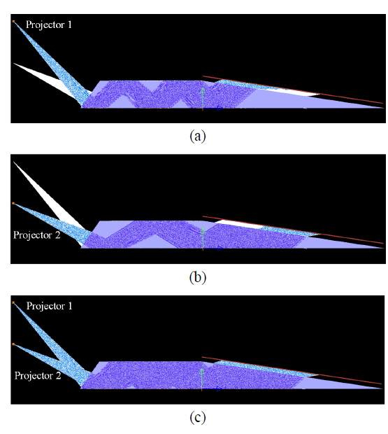
Figure 4 (a) shows the method to find and design the split imaging regions. If the 2nd imaging region can be relayed to the bottom of the 1st imaging region, a larger imaging area can be obtained. The process to find the 2nd imaging region is similar to the process to find the 1st imaging region. The conditions of each of the rays are exactly same as for the rays of the 1st imaging region. But the rays which are retraced from the 2nd imaging region are reflected more times in the wedge structure. To consider this condition, we have to retrace the path of the ray which reaches the top of the 2nd imaging region. The ray reflected at the bottom side of the waveguide arrives at the 1st imaging region as shown in Fig. 4. The reflected ray heads to the boundary between the wedge and the slab structure. After that the path of the ray can be analyzed by the same process. By extending the path of the rays to the aperture of the slab structure which is mentioned above, the projection condition to represent the 2nd imaging region can be obtained. The tiled projection scene can be displayed from each projector which represents the proper image for the designed imaging region. In this paper, we choose the bottom ray of the 2nd imaging region to make the slab length the same as that of the 1st imaging region as shown in Fig 4 (b).
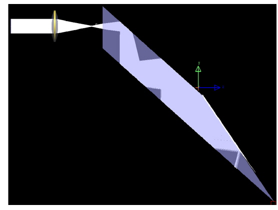
To verify the proposed method, we simulate the designed system using the optical simulation tool ‘Light Tools’ [11]. It is assumed that the structure material is an acrylic of which the refractive index is 1.5. In the simulations, the projection systems are assumed to be the point imaging source for which the projection angle distribution is limited to being under the taper angle. The simulation for the wedge projection system with the slab structure of which the thickness is 50 mm, called wedge structure 1, is performed to test the proposed design method. The thin slab structure of which the thickness is 30 mm, called wedge structure 2, is also simulated to verify the split imaging region method. The required specifications of each system are calculated based on the proposed method as mentioned above. The taper angle of wedge structure 1, of which length and thickness are 200 mm and 50 mm, respectively, is 14.04°. The length of the slab structure is 227.47 mm. According to Eq. (2), the length of imaging region is calculated as 111.01 mm. Figure 5 shows the simulation result, which is equal to the calculation value.
Wedge structure 2 is designed to represent a large scene with the thin slab structure of which the thickness is 30 mm. The lengths of the wedge and the slab are 200 mm and 207.59 mm, respectively, and the taper angle is calculated as 8.53°. Comparing with the 50 mm thickness wedge structure, the thickness and length of the slab for the thinner wedge structure is decreased. Accordingly, the length of the 1st imaging region is calculated as 61.97 mm, which is a smaller value than for the thick wedge structure. However, since the 2nd imaging region of which the length is 80.27 mm is located close by the 1st imaging region, the total merged image region is about 142.24 mm, which is a larger area compared with that for wedge structure 1. Figure 6 shows the simulation of wedge structure 2, which tests the enlarged image region with the thin wedge structure using the split imaging region method. Table 1 shows the given and calculated specifications of the wedge structures used in the simulations.
[TABLE 1.] Specification of wedge structure 1 and wedge structure 2
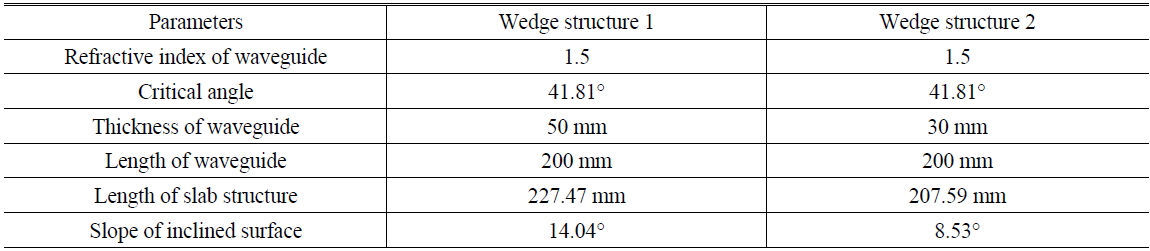
Specification of wedge structure 1 and wedge structure 2
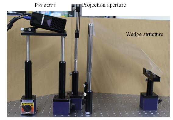
The wedge projection systems based on the simulation results are implemented to confirm the feasibility of the proposed method. The specifications of the experimental setup are matched with the simulation values. The projector (LG-HS102G) for which the resolution is XGA is used. The two wedge devices with the slab structure, the thick and the thin one, are made of acrylic material, with designs similar to the simulations.
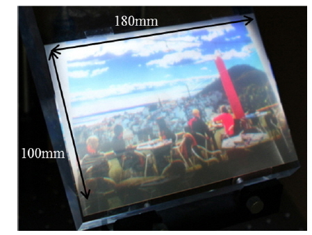
The system setup for wedge structure 1 is shown in Fig. 7. The aperture which can control the diverging angle of the projector and make the projection condition similar to the simulation is located in front of the projection device. Figure 8 shows the projected images in the wedge projection system with the slab structure. The scene size of Fig. 8 is about 180 mm by 100 mm, which is similar to the calculated length of the imaging regions, 111.01 mm. In the real system, the projector is not a point light source and the projection angle is also different from the ideal conditions, which causes the difference between the real and the simulation values.
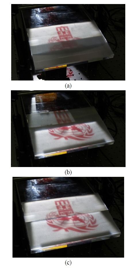
Figure 9 shows the experimental results of wedge structure 2, the thin wedge system, using the split imaging region method. Part of imaging region, not the whole area is used to reduce the key stone effect and the intensity variation. 60 mm in the 1st imaging region and 40 mm in the 2nd imaging region are activated, and the total imaging region of the system is the same as that of the thick wedge system. Therefore, a tiled projection system can be made to represent a large scene using the thin wedge waveguide device.
In this paper, we analyze the imaging process of a wedge projection system with slab structure and propose a design method to avoid the dark zone. Since the wedge-only projection system cannot provide sufficient optical path length of the projection rays, the slab structure is inevitable for the large imaging region. Using the proposed method, the proper system specifications such as the lengths of the slab structure and the imaging region can be obtained.
According to the analysis, to increase the imaging region, the waveguide should become thicker, which is undesirable for the merit of the space efficiency of the wedge projection system. To achieve a large scene with a thin wedge structure, the split imaging region method is proposed, which is a kind of tiling technique for the wedge projection system. Using two projectors for each imaging region, a large tiled scene is represented in the thin wedge structure. The ray tracing simulation using ‘Light Tools’ is performed to verify the proposed method and design the proper structure and specification values for the whole projection system. The experiments using the simulation structure are also performed to prove the proposed methods.
The proposed method can be applied to the various projection-type displays such as exhibitions and advertisements, where large size displays are required within limited space.