Transferring the optical radiation in a particular direction, and strongly localizing incident light to a nanoscale region are the roles mainly considered for nanoantennas in the nano-optics regime [1-3]. Nanoantennas can be used in sensors and photodetectors [4, 5], for enhancing the efficiency of light emission [6, 7], and in optical near-field microscopy. In recent years various kinds of nanoantennas, such as bowtie nanoantennas [8-11], Hertzian dipole optical nanoantennas [12], and Yagi-Uda nanoantennas [13-15], have been widely studied. An optical antenna can be made of multiple coupled nanoscale metallic elements to achieve a wavelength-dependent optical interaction between the metallic elements [16-18]. However, subwavelength devices composed of metallic nanostructures are used to manipulate the optical properties via propagation of surface plasmon polaritons (SPPs) or localized surface plasmon resonances (LSPRs) [18-25].
Babinet’s principle shows that a single subwavelength aperture milled in a screen of perfect electric conductor (PEC) can be modeled as an induced parallel magnetic dipole plus a normal electric dipole proportional to the polarization of the incident wave. Recently it has been shown that each nanohole in a gold film can be substituted by a magnetic dipole in line with the polarization direction of the incident magnetic field [26, 27]. Due to the small size of a subwavelength nanohole relative to the wavelength of incident light, the optical properties of a single nanohole can be analyzed based on the quasistatic approximation method [24-26]. In addition, the magnetic coupled dipole approximation (MCDA) can be used to study the interaction between two or more nanoholes. The present study deals with the interaction mechanism between two nanoholes when their separation distance is comparable to λ SPP (i.e. mλSPP/2, where m = 1 or 2). The MCDA method can be extended in the case of two nanoholes to investigate their interaction through SPP propagation. It is considered that Einc=E0ax (see Fig. 1(a)) excites a single rectangular nanohole milled in the Au film. Thus the proportional dipole magnetization related to the hole can be obtained by M = αym(ω)Hinc, where αym(ω) is the magnetic polarizability of the hole. The magnetic polarizability depends on the dielectric function of the metallic film, the dielectric material filled in the nanohole region, the LSPR wavelength of the hole, and the wave number along x- and y-axes [26, 27].
Recently it has been shown that milling a nanohole in a metallic film can be used to transform the optical energy of incident photons to SPPs, because of the established discontinuity on the smooth surface [28]. In fact, the approach of exciting the SPPs using nanoholes is one of the typical methods for generating the SPPs at metal/dielectric interfaces [29, 30]. Furthermore, a dipolar LSPR mode can be assigned to the nanohole’s optical resonance coupled to the propagating SPPs [23]. Thus, because of the coupling between the LSPR and SPPs, the radiation power spectrum at the metal/dielectric interface should exhibit optical behaviors and properties similar to those of the normalized transmission spectrum.
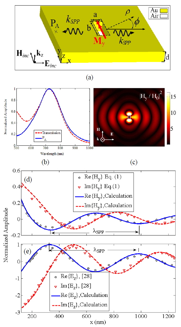
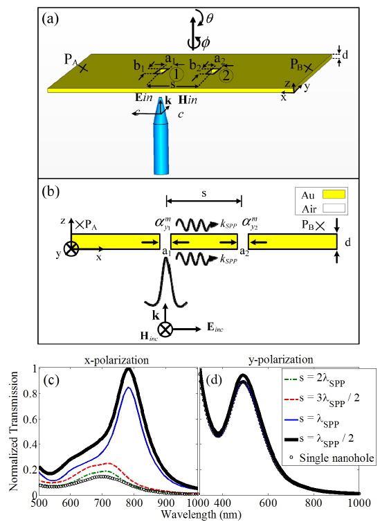
Figure 1(a) shows a schematic representation of a rectangular subwavelength nanohole, with a = 100, b = 200, and d = 100 nm, drilled in a gold (Au) film. The dielectric function of the Au film, which is dispersive at optical wavelengths, is modeled using the classical Drude-Lorentz (DL) model with five poles to account for the interband transitions [26]. The simulations are based on the three-dimensional finite-difference time-domain (FDTD) method [27], with uniform mesh sizes Δx = Δy = Δz = 5 nm. Considering x-polarized incident light, as shown in Fig. 1(a), a magnetic polarizability in line with the incident magnetic field, i.e. My, can be assigned to the subwavelength hole. The peak position of the normalized transmission spectrum of the isolated subwavelength hole is an important parameter in studying the role of the LSPR wavelength for a single hole. However, investigating the radiated optical power spectrum at an arbitrary point in the x-y plane (transverse direction) using propagating SPPs is attractive.
Considering a point A located 1 μm away from the origin on the x-y plane and above the gold film at z = 10 nm, one can evaluate the spectrum of the normalized power amplitude at that point. Figure 1(b) depicts the normalized power amplitude at point A, relative to the power amplitude of the incident light. As expected, it can be seen in Fig. 1(b) that the peak position of the power delivered to an arbitrary point along the polarization direction of incident light is similar to the peak position observed in the normalized transmission spectrum. Furthermore, Fig. 1(b) shows that the LSPR wavelength of the nanohole is coupled to the SPP waves, which means the propagated power of SPP waves is stronger at the LSPR wavelength. Figure 1(c) shows the normalized intensity of the induced magnetic field of a rectangular nanohole at λ0 = 720 nm, which shows the dipole nature of the hole at the LSPR wavelength. In the previous investigations of the optical properties of the nanoholes, each hole has been taken as an electric dipole that can be modeled using the quasistatic approximation of a dielectric void embedded in the metallic medium [25]. Hence, by setting the denominator of the related polarizability function (i.e., αe(ω)) to zero, the relevant LSPR wavelength of each hole can be obtained. As mentioned earlier, it has been shown that each nanohole in a noble metallic film can be replaced by a magnetic dipole [26]. By replacing the hole with a magnetic dipole, one is able to enhance the theoretical discussion based on the properties of a magnetic dipole (for a single hole) and the interaction of two magnetic dipoles (for the case of hole dimers). In addition, the SPP wavelength at the LSPR wavelength can be obtained as . The λSPP can be obtained directly from the electric/magnetic field distributions along the propagation direction (x-axis in the present case), according to the spatial difference of maximum peak positions of field components (Ex, Hy, Ez) at the LSPR wavelength. The theoretical formulation for computing Ex and Ez components of a circular nanohole has been presented based on the Hankel functions, which are composed of Bessel functions of the first and second kinds with integer orders [27, 29].
Due to the small size of the nanoholes, the asymptotic equations can be approximately used for circular and rectangular holes with different LSPR wavelengths [27]. Thus, considering a proper kSPP at the LSPR wavelength one can use the Hankel-function-based equations to find the electric and magnetic field components of the propagated SPP wave. Applying Maxwell’s equations in the cylindrical coordinate system (ρ, φ, z) to the Ex and Ez components, and considering EφSPP= 0 and also H1(1)(kSPP ρ) as the Hankel function of the first kind and first order, the propagated magnetic field of the SPP wave can be obtained:
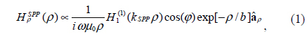
where kSPP is the wave number of the propagated SPP. The exponential term in Eq. (1) represents the decay factor of the propagated SPP, in which b = 1/(2Im[kSPP])is the attenuation length of the optical energy of the SPPs. Although the LSPR wavelength depends on the geometrical shape of the nanohole, the propagation of SPPs at the metal/insulator interface can be well approximated using Hankel functions. Thus the propagated SPPs of a rectangular nanohole can be evaluated by Eq. (1) as the radiation fields of a magnetic dipole.
Figure 1(d) demonstrates the normalized amplitude of the real (solid line) and imaginary (dashed line) parts of the calculated Hy for the propagated SPP along the x-axis, compared to the real (circles) and imaginary (triangles) parts of the induced magnetic field of the SPP wave using Eq. (1) for the nanohole. Furthermore, Fig. 1(e) shows the normalized amplitude of the real (solid line) and imaginary (dashed line) parts of the calculated Ez electric field component of the propagated SPP along the x-axis at the LSPR wavelength λ0 = 720 nm. The real and imaginary parts of Ez are compared to the real (circles) and imaginary (triangles) parts of the electric field Ez obtained from Ref. [28]. Apparently, regarding Figs. 1(d) and 1(e), the electric and magnetic fields of the propagated SPP wave at the LSPR wavelength of the hole can be well approximated by the Hankel functions. Moreover, as seen in Figs. 1(d), and 1(e), the SPP wavelength can be directly computed using the maximum (minimum) peaks of the electric (magnetic) field, correspondingly, which confirms the value obtained from the theoretical formula, λSPP 670 nm. It should be noted that the minimum in the transmission spectrum at wavelengths below λ0 = 600 nm is due to the interband transitions of the gold film [26].
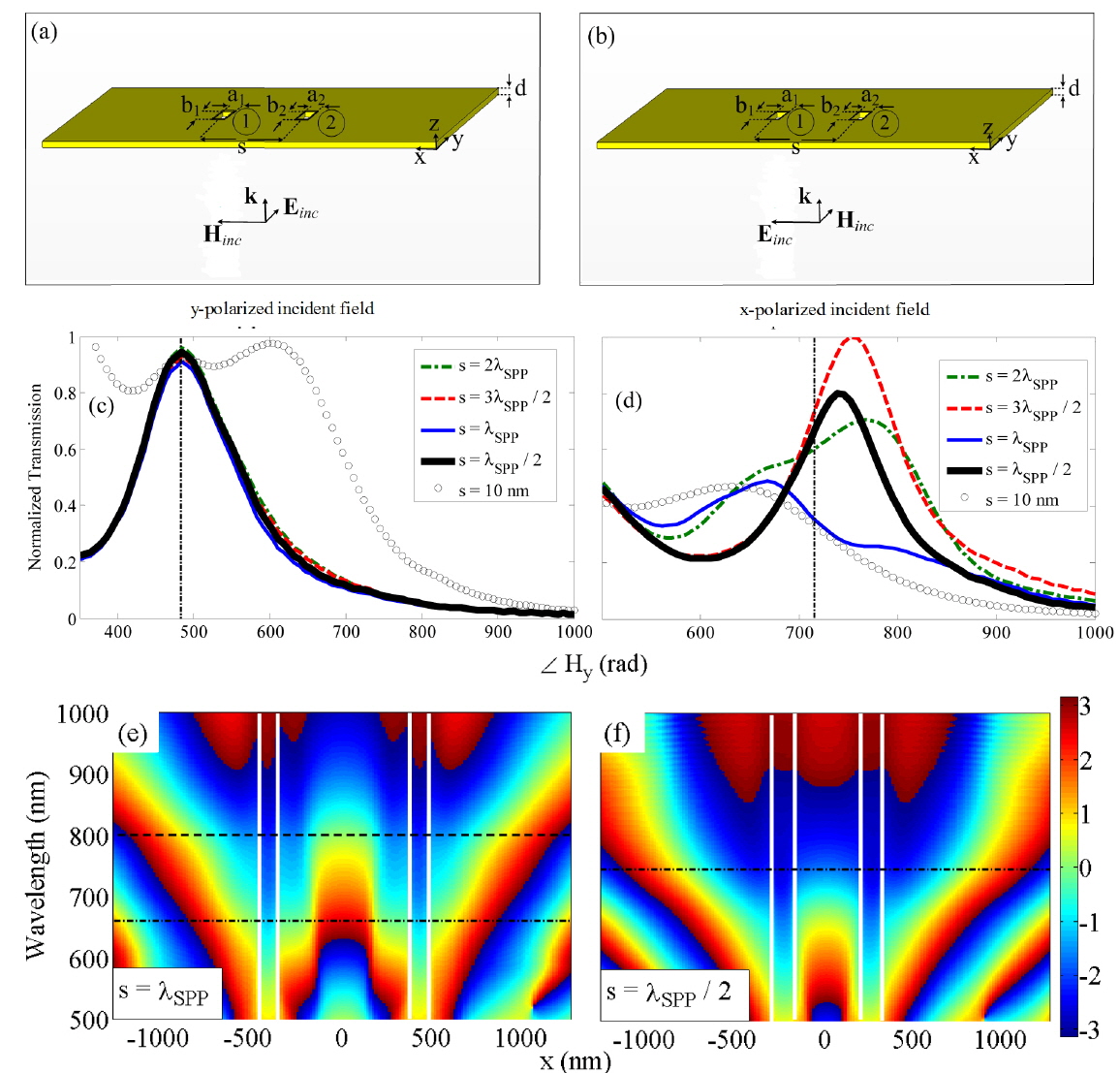
Figures 2(a) and 2(b) depict schematic representations of two nanoholes drilled in an Au film, separated by a center-to-center distance s and illuminated by plane-wave incident light polarized along the y- and x-axis directions respectively. Figures 2(c) and 2(d) show the normalized transmission of the nanohole pair by s = 2λSPP (dashed-dotted line), 3λSPP/2 (dashed line), λSPP (solid line), λSPP/2 (thick solid line), 10 nm (triangles), and also a single nanohole (circles) under y- and x-polarizations, respectively.
Regarding Fig. 2(c), it can be seen that the normalized transmission of the nanohole pair, with s = 2λSPP, 3λSPP/2, λSPP, and λSPP/2 under a y-polarized incident field, behaves similarly to that of a single nanohole. This is due to the fact that the direction of the propagated SPP is consonant with that of the incident electric field polarization. Moreover, according to Fig. 2(c) it can be inferred that for polarization of the incident electric field perpendicular to the nanohole-pair axis, weak coupling occurs for separation distances comparable to the SPP wavelength, because when the incident electric field is thus polarized no SPP can propagate between the nanoholes. Decreasing the distance from s = λSPP/2 to 10 nm leads to strong coupling between the nanoholes, due to the near-field optical interaction. The strong near-field interaction has been modeled as the near-field interaction of the equivalent magnetic dipoles using the MCDA method [26].
Nevertheless, the optical interaction of the nanohole pair under excitation by x-polarized incident light is completely different. Based on Fig. 2(d) it can be seen that reducing the distance from s = 2λSPP to λSPP/2 leads to enhancement of the transmission spectrum. For s = 10 nm (Δx = Δy = Δz =2 nm) it is seen that the nanohole pair resonates at the wavelength of a single nanohole with an enhanced transmission amplitude, which is due to the doubling the cross section of the apertures. In fact, for this polarization direction of the incident wave, the near-field optical interaction between the holes is negligible. Additionally it can be seen from Fig. 2(d) that for s = 2λSPP, and λSPP two resonant peaks are obvious in the transmission spectrum, while for s = 3λSPP/2 and λSPP/2 the transmission spectrum presents just one resonant peak. To study this effect according to the interaction of the magnetic dipoles, the phase variations of Hy versus wavelength are presented in Figs. 2(e) and 2(f).
It should be noted that, in the case of uniform excitation of the nanohole pair using an incident plane wave polarized along the pair axis, because both of the nanoholes are illuminated uniformly they can interact in-phase throughout the spectral band. This can be seen in Figs. 2(e), and 2(f). In the cases of s = 2λSPP and λSPP, because of the destructive interference of the SPPs at the metal/dielectric interface, a charge distribution occurs between the holes. According to Fig. 2(f), this charge distribution generates a quasi-magnetic dipole that can interact with the nanohole pair, in-phase at the short-wavelength (horizontal dash-dotted line) and antiphase at the long-wavelength (horizontal dashed line) peak. For s = 3λSPP/2, and λSPP/2, in which the constructive SPP interference occurs between the holes [28, 29], the generated charge distribution interacts in-phase with the magnetic dipoles proportional to the nanoholes (see Fig. 2(f)).
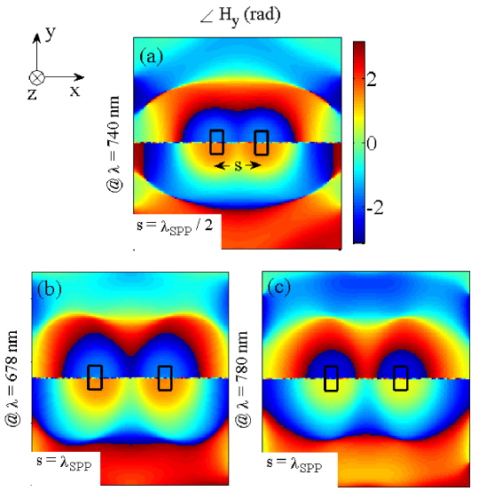
Figures 3(a)-3(c) show the phase variations of the induced magnetic field Hy for s = λSPP/2 at λ0 = 740 nm, and s = λSPP at λ0 = 678 and 780 nm, respectively. The charge distributions due to the interference of the SPPs between the nanoholes are denoted by dashed ellipses. According to Fig. 3(a) for s = λSPP/2 at λ0 = 740 nm, this charge distribution is in-phase with the magnetic dipole of each hole. Similarly, for s = λSPP the interference of SPPs produces two different kinds of charge distributions at λ0 = 678 nm and 780 nm, which can interact with the magnetic dipoles of the holes as in-phase and antiphase dipoles, respectively.
Most previous investigations of nanoholes have dealt with the optical properties of a single hole [23, 25], or hole dimers and arrays [26, 29, 32-35]. Nevertheless, the optical properties of single antenna excitation of the nanohole pair, and the circumstance of optical interaction between them, have not yet been studied. In the next section, the optical properties and interactions between the nanohole pair under single antenna excitation are investigated.
It has been shown that the optical single antenna excitation of two nanoparticles [16-18] and array of nanowires [13] leads to directional optical radiation, which improves the application of nanoantennas. Simulations and measurements [16] have been studied using electric dipole theory and the coupled dipole approximation (CDA) method.
Although the role of the hybridized plasmon resonances in directional radiation from nanoparticles has been investigated, the role of SPPs in the directional radiation of a nanohole dimer can be subtle. The ability to model the interaction of nanoholes with the magnetic coupled dipole approximation (MCDA) method encourages us to develop the idea of single antenna excitation of nanostructures for the nanohole-pair structure. Figure 4(a) shows the single antenna excited nanohole pair with s = nλSPP/2 where n = 1−4, such that only hole 1 is locally illuminated by x-polarized, focused incident light from a near-field optical tip. The schematic representation of the structure used in formulating the modified magnetic polarizabilities according to the MCDA method is shown in Fig. 4(b). It is considered that a/b = 1/2 with a1 = a2 = 100 nm and b1 = b2 = 200 nm respectively. Considering the radiated magnetic field of each nanohole to be H= m・exp(ikSPPs)[kSPPs2 / s+ikSPP / s2]/4π, and also using Eq. (1), the modified magnetic polarizability of the nanoholes interacting through SPP waves can be obtained as:
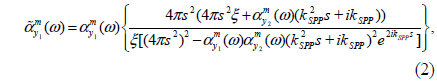
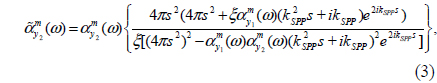
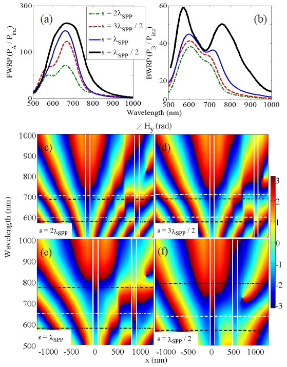
where εm(ω) is the relative permittivity of the gold film, εd is the relative permittivity of the dielectric medium (air), k0 = 2π /λ0, and λ0 is the wavelength of the incident light in free space. The parameter ξ is the amplitude ratio related to the damping of the incident field at hole 2. The value of ξ can be easily computed based on the attenuation length of the optical energy of the SPP waves at the position of hole 2. In addition, Fig. 4(a) shows the two probing points A and B used to study the power propagated through SPPs. It is supposed that points A and B are 1 μm away from nanoholes 1 and 2 respectively. Thus the spectral behavior of the optical power at points A and B, normalized to the incident optical power and the areas of the holes (2×2×(a+b)), can be used to examine the optical power at points A and B. Figures 5(a) and 5(b) demonstrate the normalized radiated power probed at points A and B for s = 2λSPP (dashed-dotted line), 3λ SPP/2 (dashed line), λSPP (solid line), and λSPP/2 (thick solid line) respectively. For the sake of simplicity, the normalized radiated powers are called forward radiated power (FWRP) for PA and backward radiated power (BWRP) for PB, correspondingly. According to Figs. 5(a) and 5(b), two resonant peaks are obvious in the normalized BWRP and FWRP spectra. The short- (first mode) and long-wavelength (second mode) peaks are proportional to the in-phase/antiphase interaction of the magnetic dipoles related to the nanoholes, depending on the separation distance.
[FIG. 5.] Normalized (a) FWRP, (b) BWRP for s = 2λSPP (dashed-dotted line), 3λSPP/2 (dashed line), λSPP (solid line), and λSPP/2 (thick solid line). The phase variation of the induced magnetic field Hy along the x-axis versus wavelength for s = (c) 2λSPP, (d) 3λSPP/2, (e) λSPP, and (f) λSPP/2, for the structure shown in Fig. 3(a). The vertical solid lines depict the positions of nanoholes, and the horizontal white and black lines show the in-phase (dashed-dotted line) and antiphase (dashed line) interaction wavelengths of the nanoholes at the FWRP and BWRP first and second modes, respectively.
Figures 5(c)-5(f) demonstrate the phase variations of the induced magnetic field Hy along the SPP propagation direction (x-axis) versus the wavelength of incident light for s = 2λSPP (c), 3λSPP/2 (d), λSPP(e), and λSPP/2 (f) respectively. The vertical solid lines in Figs. 5(c)-5(f) mark the positions of the nanoholes, while the horizontal white and black lines specify the phase variations of the induced magnetic fields at the peak wavelengths of the FWRP and BWRP spectra respectively. According to Fig. 5(a), two resonant modes can be seen in the FWRP spectrum for s = 2λSPP and 3λSPP/2, where by reducing s the first mode disappears gradually. Besides, the amplitudes of the FWRP and BWRP show that reducing s results in stronger interaction between the holes. In addition, reducing s leads to a small redshift of the second mode peak, a blue-shift of the first mode peak, and also an increase in the amplitudes of both mode peaks in the BWRP spectrum. Figure 5(c) shows that for s = 2λSPP, at the first modes of the FWRP (black dashed-dotted line) and BWRP (white dashed-dotted line) the induced magnetic field Hy is in-phase (dashed-dotted-lines), while at the second modes of FWRP (black dashed line) and BWRP (white dashed line) the induced magnetic fields of each hole are antiphase (dashed lines) at the centers of the holes. As demonstrated in Fig. 5(d) for s = 3λSPP/2, the induced magnetic fields of the nanoholes are antiphase and in-phase for the first and second modes of the FWRP and BWRP respectively. The same results are evident for s = λSPP and λSPP/2 in Figs. 5(e) and 5(f), correspondingly. The peaks of the FWRP spectrum for s = λSPP, and λSPP/2 elucidate the in-phase and antiphase interactions of the magnetic dipoles relevant to each nanohole. Thus it can be stated that the interaction between the magnetic dipoles (analogous to the nanoholes) via the SPP waves strongly depends on the distance between the holes. In fact, when s = λSPP/2 and 3λSPP/2, the SPPs experience constructive interference, while for s =λSPP and 2λSPP destructive interference occurs [21, 30]. Thus the optical interactions between the nanoholes with s = λSPP/2, and λSPP deserve investigation. Because of significant distances between the nanoholes, i.e. kSPPs > 1 for s =λSPP/2 and kSPPs >> 1 for other distances, the far-field interaction of the holes is supposed for the analytical method. Although for all distances kSPPs > 1, a general case is considered in Eq. (2) and Eq. (3), i.e. accounting for the terms 1 / s2 and 1 / s in the optical interaction, because for s =λSPP/2 nanohole 2 is not completely in the far-field region of nanohole 1. For distances greater than s = λSPP/2, the term 1 / s2 can be neglected for the sake of simplicity.
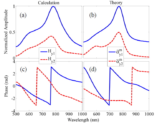
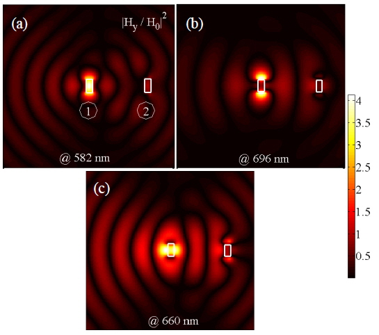
Figures 6(a)-6(d) show the near-field normalized amplitude and phase of Hy obtained from calculations (Figs. 6(a) and 6(c)) and from the theory using Eqs. (2) and (3) (Figs. 6(b) and 6(d)) for s = λSPP at the center of nanoholes 1 (solid line) and 2 (dashed line), respectively. According to Figs. 6(a) and 6(c), the first and second modes at λ0 = 582 and 780 nm, the magnetic dipoles can interact in-phase and antiphase, respectively. The modified magnetic polarizabilities calculated theoretically using Eqs. (2), and (3) are in good agreement with the near-field calculations. Based on these results for the interaction properties of the nanoholes in the case of single antenna excitation, one may expect directional radiation from the nanohole pair shown in Fig. 4(a). To investigate this effect, it is appropriate to compute the directivity of the structure shown in Figs. 4(a), and 4(b). Supposing the points A and B as probing points for the forward (FW) and backward (BW) power radiation, respectively, the forward-to-backward directionality can be obtained as follows [16]:

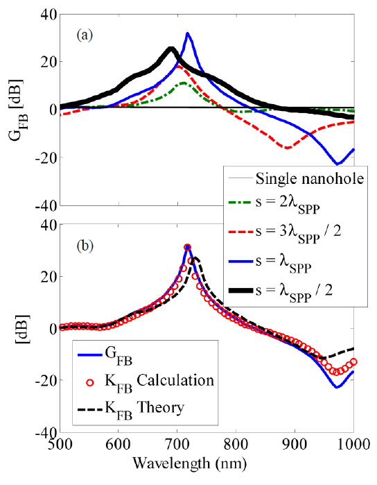
Thus, using Eq. (4) one can obtain proper insight about the far-field radiation of the single antenna excited nanohole pair, compared to the radiated power from a single nanohole. Figure 7(a) shows the directionality of a single nanohole (thin solid line) and of a nanohole pair separated by s = 2λSPP (dashed-dotted line), 3λSPP/2 (dashed line), λSPP (solid line), and λSPP/2 (thick solid line), respectively. It can be seen that in the case of the nanohole pair, a directional radiation occurs, compared to the radiation from a single nanohole. Moreover, it is evident that reducing s leads to directionality enhancement.
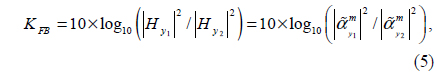
According to Fig. 7(a), it is obvious that although the near-field interaction for s = λSPP/2 is stronger than for other distances, its proportional GFB is smaller than the obtained directionality for s = λSPP. This phenomenon is due to the edge-scattering effects that may reduce the interaction of the nanoholes through SPP waves. Moreover, considering the near-field values of Hy for each nanohole and also the relevant modified magnetic polarizabilities, the near-field directionality KFB which is reciprocal to GFB can be obtained as follows:
where the induced magnetic fields |Hy1| and |Hy2| are taken to be at the centers of the nanoholes, correspondingly.
Figure 7(b) shows the directionality GFB (solid line) and KFB obtained using calculations (circles) and the theory (dashed line) based on Eqs. (2), (3), and (5) for s = λSPP. According to Fig. 7(b), it can be seen that the theory of reciprocity is verified for the nanoholes (magnetic dipoles), and also supported by the MCDA method. This verification is also obtained for other separation distances (not shown here).
Figures 8(a)-8(c) show the intensities of the induced magnetic fields of the single antenna excited nanohole pair for s = λSPP at the resonant peaks of the BWRP and FWRP spectrums, i.e. λ0 = 582, 696, and 660 nm. Figure 1(c) and also Figs. 8(a)-8(c) show that milling nanohole 2 in the metallic film can manipulate the propagation of the SPP waves. This is in contrast with SPP propagation from a single nanohole, for which no directionality may occur along the propagation direction of the SPPs at the metal-dielectric interface.
Furthermore, at λ0 = 660 nm (the resonant peak wavelength of the FWRP), the SPPs are highly directed in the FW direction, compared to the resonant peaks of the BWRP spectrum (i.e. λ0 = 582, 696 nm). In this study it is assumed that nanohole 1 is excited by a focused Gaussian wave that can be modeled as follows in the FDTD method calculations:
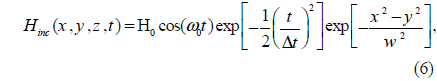
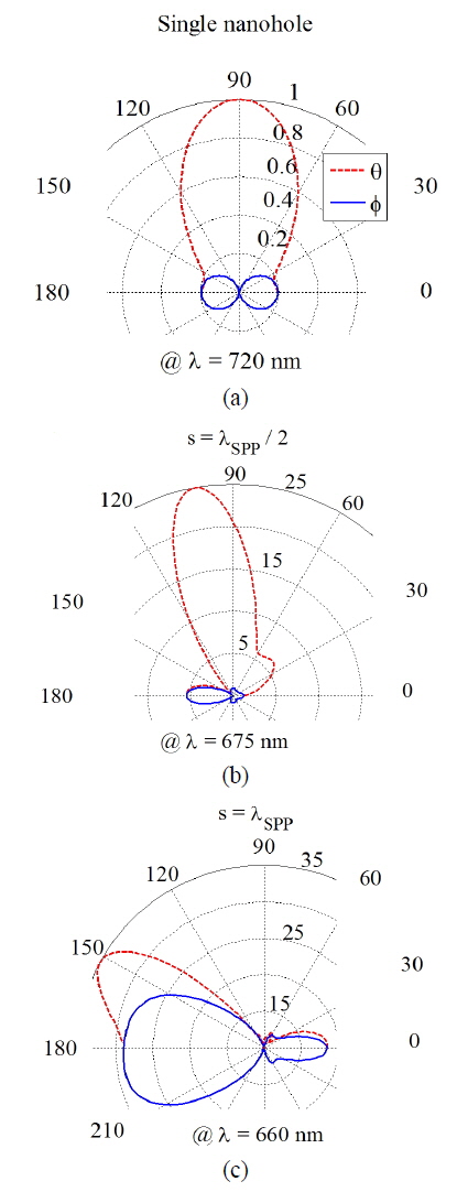
where H0 is the amplitude of the incident wave, w = 200 nm is the beam width of the incident Gaussian wave, ω0 = 2πc / λ0 is the free-space angular frequency, and Δt is the time step, the proper value of which can be identified using the Courant-Friedrichs-Lewy (CFL) stability condition [31]. The radiation pattern of the single nanohole at λ0 = 720 nm, and also the radiation patterns of the single antenna excited nanohole pair for s = λSPP/2, and λSPP at λ0 = 675, and 660 nm, are shown in Figs. 9(a)-9(c) respectively. It can be seen that the single antenna excited nanohole pair for s = λSPP/2, and λSPP radiates directionally in θ (dashed line), 0 ≤ θ≤ π, and ϕ (solid line), 0 ≤ ϕ≤ 2π, directions in the yz and xy planes, respectively.
It can be seen that increasing the separation distance from s = λSPP/2 to λSPP results in rotating the radiation pattern from 100 to 150 degree in the θ direction, and also in increasing the amplitude of the radiation pattern in the ϕ direction from 5 dB to 28 dB. Moreover, in the case of the single_antenna excited nanohole pair, the main beam of the radiation pattern deviates from the single-nanohole radiation (i.e. θ = 100° for s = λSPP/2 and θ = 150° for s = λSPP). Although the BWRP radiation increases with increasing s, the amplitude of the FWRP radiation drastically increases, which is in agreement with the previous statements about the GFB spectrum for s = λSPP/2, and λSPP.
In conclusion, the optical interaction of two rectangular nanoholes in a gold film via SPP propagation is investigated in different polarizations, under uniform and single antenna excitation modes. It is shown that for both uniform and single antenna excitations, when the incident electric field is polarized along the axis of the nanohole pair, the nanoholes can interact through SPP waves. In addition, in the case of single antenna excitation, the radiation power spectrum in the FWRP and BWRP directions exhibits two resonant peaks, related to the in-phase and antiphase interaction of the magnetic dipoles corresponding to each nanohole, and strongly dependent on the distance between them. Our finding shows a directional power radiation due to the in-phase and antiphase interaction of magnetic dipoles. Interestingly, the direction of the radiated power for the nanohole pair deviates from the radiation of the single nanohole, depending on the separation distance. As expected, in the case of uniform excitation the nanoholes can interact in-phase throughout the spectrum. Moreover, it is shown that for the case of uniform excitation with s = λSPP/2, and 3λSPP/2, the normalized transmission spectrum exhibits two resonant peaks, in contrast to the case with s = 2λSPP, and λSPP. Based on the phase diagrams of the induced magnetic fields along the x-axis, it is demonstrated that these resonant peaks are due to the destructive interference of the SPPs, resulting in an additional charge distribution in the region between the nanoholes. According to the normalized transmission spectrum, it is shown that the consequent dipole of this charge distribution interacts in-phase (at the short wavelength peak) and antiphase (at the long wavelength peak) with the magnetic dipole of the nanoholes.


![(a) Schematic representation of the induced magnetic dipole My for a subwavelength rectangular nanohole (a×b) milled in an Au film. (b) Normalized power amplitude relative to the incident-field power amplitude, measured at point A. (c) Intensity of the induced magnetic field (|Hy/ H0|2)of the nanohole with a = 100, b = 200, and d = 100 nm under plane-wave illumination at λ0 = 720 nm. Normalized amplitude of the (d) real (solid line) and imaginary (dashed line) parts of the calculated induced magnetic field component Hy of the propagated SPPs of the rectangular nanohole along the x-axis at λ0 = 720 nm (LSPR wavelength), in comparison with the real (circles) and imaginary (triangles) parts obtained using Eq. (1), and the (e) real (solid line) and imaginary (dashed line) parts of the calculated Ez in comparison with the real (circles), and imaginary (triangles) parts of the Ez component of the propagated SPPs of the rectangular nanohole along the x-axis obtained from Ref. [28] at the LSPR wavelength.](http://oak.go.kr/repository/journal/16147/E1OSAB_2014_v18n6_799_f001.jpg)