We propose a new development for calculating a computer-generated hologram (CGH) through the use of multiple general-purpose graphics processing units (GPGPUs). For optimization of the implementation, CGH parallelization, object point tiling, memory selection for object point, hologram tiling, CGMA (compute to global memory access) ratio by block size, and memory mapping were considered. The proposed CGH was equipped with a digital holographic video system consisting of a camera system for capturing images (object points) and CPU/GPGPU software (S/W) for various image processing activities. The proposed system can generate about 37 full HD holograms per second using about 6K object points.
Holography is a kind of visualization system which naturally reconstructs 3-dimensional (3-D) objects in space, storing all the intensity and phase information of light [1]. Recently, there has been increasing interest in broadcasting using holographic technology, together with the popularization of 3-D display techniques [2, 3].
Because the CGH technique requires a huge amount of calculations (for example,
Singapore University proposed an algorithm to change the CGH equation into an exponential function to represent the complex terms and allow calculation of the real and imaginary terms separately [4]. They made a look-up table for each term to increase the calculation speed and implemented them with a GPU from nVidia. It takes 0.3s to calculate a CGH with 1K object points and 1,024×768 hologram resolution. The Zhongshan University team in China used a mesh-model in CGH calculation and implemented it in a GPU [5]. The research team at Chiba University modified Yoshikawa’s equation to recursively calculate the horizontal or vertical hologram pixels. They implemented this scheme in an AMD GPU with some programming skills for the calculation of one CGH with HD resolution in 30ms [6]. Recently, research based on multiple GPUs has also been carried out. Park et al. evaluated a practical approach for implementing CGH using two graphic processing units (GPUs) [7], while Seo et al. developed a parallelization method for CGH using 4 GPGPUs [8]. Kim et al. developed a one-dimensional novel-look-up-table (1-D N-LUT) which was implemented on the graphics processing unit of GTX 690 for the real-time computation of Fresnel hologram patterns of three-dimensional (3-D) objects. This system can generate almost 3 frames of Fresnel holograms with 1920×1080 pixels per second for a 3-D object with 8K object points [9]. Smithwick et al. developed an approach of rapid hologram generation for realistic 3D image reconstruction based on the angular tiling concept using a new graphic rendering approach integrated with a previously developed layer-based method for hologram calculation. The proposed method reduced the computation time of a single-view hologram to 176 ms [10]. Ito et al. reported a method for fast computation of computer-generated holograms (CGHs) using the Xeon Phi coprocessors recently released by Intel, which have massive amounts of x86-based processors on one chip. The computational time for 10K object points was 0.141s using the recurrence relation method [11].
Since there are various methods of generating and displaying digital holograms, it is very difficult to propose a standard system for processing a digital hologram video. We developed a new system to obtain 3-D object point information using a vertical-type hybrid camera system with an RGB and depth camera, and we used it to calculate CGHs [12]. The present paper focuses on hologram generation using GPGPUs.
The remainder of this paper is organized as follows. A hologram video system is described in Section 2, and the method of CGH development is presented in Section 3. Section 4 describes the implementation results, while Section 5 provides a summary of the proposed method and system.
Optical capturing is an ideal method, but due to difficulties of system configuration and optical shooting, the computer-generated hologram has widely been used. In order to calculate CGHs, 3-D information about the target object is needed. Depth information can be obtained through various methods. Herein, a depth camera, which has recently gained wide use, was used. An RGB camera is also used to obtain the brightness and chrominance information of the target. Through the CGH calculation process, the obtained object points are converted into holograms. Holograms can be calculated for the transmitter (TX) or the receiver (RX). In the case of calculating CGHs on the RX, the object point information, rather than a hologram itself, is transmitted. The service issue requires additional explanation and discussion, which is beyond the scope of this paper [12, 13].
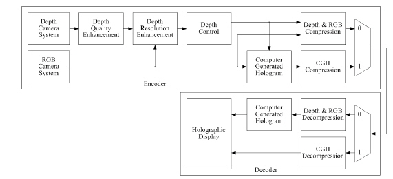
There are various types of systems for providing video service using digital holographic technology based on the CGH [13]. Among such systems, a method for the generation and display of natural scene-based holograms is presented in Fig. 1. The system may be configured differently by the position for calculating CGHs on either the encoder or the decoder. If the CGH process is performed on an encoder, the holograms are encoded (compressed). Otherwise, the object point information (depth and RGB) is encoded. The system generates good holograms under a constrained shooting environment, but it is difficult to obtain depth with high resolution and visual quality due to the short imaging distance of the depth camera and interference/scattering of the infrared (IR) rays.
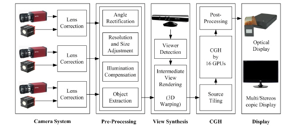
The proposed architecture for the generation and reconstruction of digital holograms is depicted in Fig. 2. The system performs the CGH process on the encoder side. The generation system is composed of a Camera System, as well as the Pre-processing, View Synthesis and Computer-Generated Hologram (CGH) parts. The Display system displays digital holograms using a spatial light modulator (SLM). If there is no holographic display, the CGHs are converted into 2-D, 3-D stereoscopic, or multi-view images, which are then displayed [12].
III. COMPUTER GENERATED HOLOGRAM
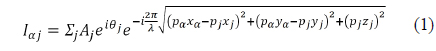
A hologram is an optical pattern that is generated by interference between an object and a reference wave. The CGH is a mathematical modeling method for holography. The light intensity of the CGH is defined in Eq. (1). Equation (1) can be used to generate both real and imaginary holograms, and the proposed system uses both types of holograms for reconstruction quality. When the reference wave is parallel and the hologram plane is sufficiently distant from the object plane, Eq. (1) is approximated to Eq. (2).

If a color hologram is created using the CGH, Eq. (2) must be performed three times, once each for the R, G, and B components. Since the color components of a hologram use different wavelengths, each calculation should be performed individually. That is,
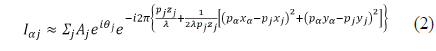
As shown in Eq. (1) or (2), CGH requires a huge amount of iterative calculations, which can be improved by the use of GPGPU. Figure 3 shows two graphical methods of CGH calculation using Eq. (2). If the position of a holographic pixel assumes a thread of GPU, the method of Fig. 3(b) provides a more regular structure. This regularity of the calculation is an essential characteristic for the successive development of GPGPU. The method concurrently calculates all holographic pixels with valid object points in massive threads of GPGPU. The intermediate results are stored in threads until obtaining the final hologram, minimizing memory access, which is the most critical problem in GPGPU development.
3.2. Object Point Tiling and Memory Selection
For calculating a holographic pixel, the multiplication result of the terms for the position and intensity of object points is accumulated; however, if the intensity is zero, the accumulated value is not present. The object points with no intensity are invalid. Thus, calculation performance can be improved if only the valid object points are selected and loaded to GPGPUs [14].
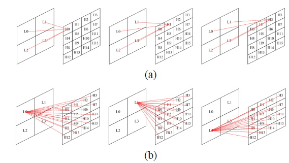
There are huge amounts of fetch operations for object points during the generation of a hologram. Performance can also be improved by utilizing constant memory or shared memory, which are types of cache memory, instead of global memory [15]. Shared memory is the fastest, but it is only internally accessible in a block. If shared memory is used for storing object points, the object points are repeatedly loaded in all blocks from the global memory. Thus, the use of shared memory decreases the performance in comparison with the case of global memory. Constant memory can be accessible for all blocks and threads in GPGPU, but has size restrictions for data storage. Thus, the valid object points should be transferred to the constant memory according to the memory limitation and the number of GPGPUs used after they are separated (or tiled). The tiling method is shown in Fig. 4. In Fig. 4(a), the valid object points (gray parts) were selected, then transferred to Devices 0~3, which correspond to GPGPUs. Figure 4(b) shows the operation scheme using the tiling method according to the size of the constant memory or calculation performance.
The estimated time, which is the average value for the generation of 20 holograms, is listed in Table 1. The hologram had the size of 1,024×1,024, which was calculated with 1K valid object points. The initial LUT setting time and the CPU-to-GPGPU transfer time were not included in the data of Table 1. The method using only constant memory had the minimum operational time of 31.137 ms.
[TABLE 1.] Average calculating times according to memory types
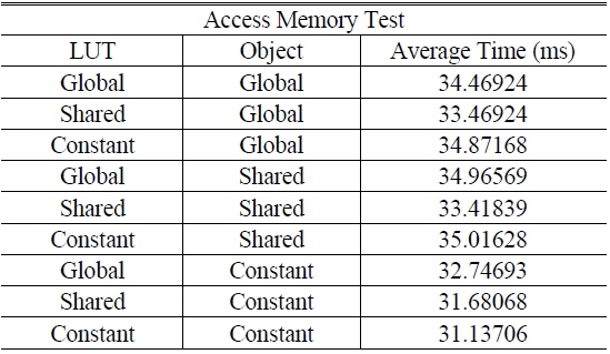
Average calculating times according to memory types
A thread for calculating a hologram requires at least 8 registers: 4 for the data (
For calculating a holographic pixel, 2 registers are required to accumulate a real and imaginary term. If a thread deals with
Since each component of the information (


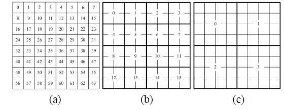
In the case of calculating multiple hologram pixels in a thread, performance can be improved by register sharing. However, all resources cannot be utilized if the size of the tiled hologram is smaller than the number of available threads at a time. Thus, the minimum number of tiles should be larger than the maximum number of threads used [14].
The method of hologram tiling is shown in Fig. 5. In Fig. 5(a), each thread processes a hologram pixel. In Fig. 5(b) and (c), each thread processes a 2×2 block and a 4×4 block, respectively. In the case of Fig. 5(b) and (c), each thread needs 20 (= 8 + (2 + 2) + 2(2 × 2) and 48 (= 8 + (4 + 4) + 2(4 × 4)) registers, respectively, as calculated using Eq. (3).
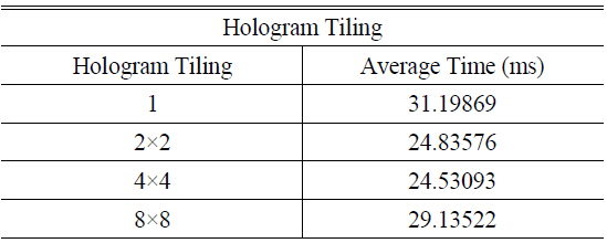
Table 2 shows the average calculation time. In this experiment, the hologram was tiled to 1, 2×2, and 4×4, and mapped to a thread. The 1,024×1,024 hologram was generated using 1K object points, and only the constant memory was used for the storage of object points and LUTs. There were 512 allocated threads in a block, and 64 registers could be allocated in a thread because the maximum number of registers in a block is 32,768. If a 4×4 tile is calculated in a thread, then 48 registers are used in the thread. Since an SM can accommodate 3 blocks and a GPGPU includes 16 SMs, a total of 393,216 pixels which can be calculated concurrently. Therefore, for generating a 1,024×1,024 hologram, 2.67 calculations are needed.
[TABLE 2.] Average calculation times according to hologram tiling

Average calculation times according to hologram tiling
Table 3 shows the average calculation time for a 1,024 × 1,024 hologram with 1K object points, according to the number of threads in the block of a GPGPU. GTX 780 Ti has 2,048 SPs in an SM, and an SM can be configured with 2 blocks in which there are 1,024 threads. When a block has 1,024 threads and the bandwidth of memory access is 96.48GB/s, the block has the performance of 5,046 GFlops for floating point calculation. Since object points and LUTs use the constant memory, in the case of 1K valid object points all threads access the memory twice, and the ratio of CGMA is 10:1.
[TABLE 3.] Average calculation times according to the number of threads in a block
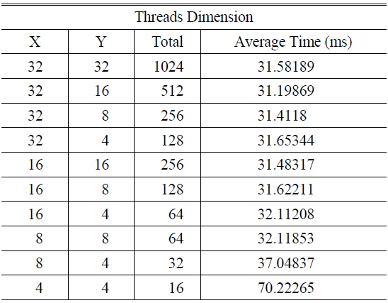
Average calculation times according to the number of threads in a block
In the case of applications with a massive amount of memory access such as for a CGH, the performance of the system can be improved according to the memory access method as well as the memory mapping method employed. If there is global memory such as a GPGPU and only single access is allowed at a time, they become the most import issues for successive implementation.
Global memory consists of dynamic random access memory (DRAM). It activates all data in a column of a bank to access a certain memory position. A cell in a DRAM stores or fetches data by charging and discharging a capacitor. For improvement of the integrating ratio of the cell and decrease of the time required for charging and discharging a capacitor, the capacitor is very tiny in size. Due to the physically small size of a capacitor, its charge is easily leaked by various operations such as read and write. Thus, a periodic amplifying operation should be required, which is defined as an activation operation. Since the activated data of a column is different from the data in a bank, it should be updated to the data of a bank, which is defined as pre-charge. In the case of changing a column address, the pre-charge operation should be executed. The reason that memory access requires a large time is because of executing frequent activation and pre-charge in the operation of read and write. To reduce memory access time, numerous read and write operations should be performed once a column is activated. The use of independent activating operation between banks may also offer a chance to improve memory access. Since each bank is independently activated, the different columns of banks can be accessed without updating operation.
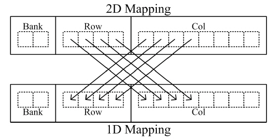
As described previously, it is very advantageous to execute many access events for an activated column without changing the column. Since a hologram is tiled during calculation of a CGH and the tiled holograms are stored in the global memory, many changes of the column address are required. In this case, the many activation operations increase the delay time. Figure 6 shows the change from 2D (dimensional) image data to 1D image data format. If the total amount of 2D image data is smaller than the length of a row, the 2D data can be stored in a row by substituting significant bits of the column and row address.
Holograms are generated with non-zero object points, and the data is in 1D format. In the case of accessing multiple banks, the delay times for activating operations are independent of each other and are hidden by normal read and write operation. According to the number of banks used, the effect of increase of the length of the row address occurs, thus allowing decrease of the delay time.
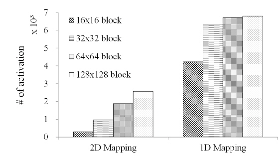
The results for the average number of activations when a 512×512 hologram is generated for two cases, 2D and 1D mapping, are shown in Figure 7, according to different block sizes. When a hologram pixel block is stored in a row of a bank, the activating operation is decreased to 1/3 of the rate. From this experiment, it was demonstrated that block-based storage to a row has better performance.
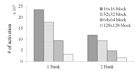
Figure 8 shows the results for the average number of activations according to the different number of banks and block sizes. When the number of the banks used was increased, the activating operation was decreased to 1/2 the rate. If an algorithm or operational scheme was not changed, the number of activations indeed remained unchanged, but the operation time could be decreased due to the independent operation of bank activation. From this experiment, the number of banks and memory mapping scheme were determined to affect system performance.
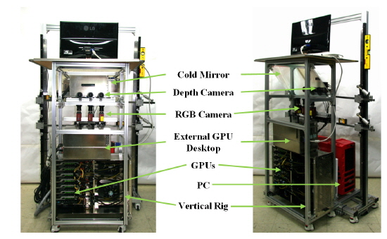
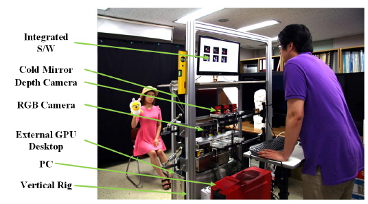
Each algorithm of the camera input, pre-processing, rectification, and post-process was implemented using C/C++ and OpenCV, and the CGH and S/W reconstruction for testing were implemented using CUDA. The Geforce GTX780 Ti was used for GPGPU, and 8 GPGPUs were equipped in our system. Each S/W engine was integrated into the LabView environment. The 30 MHz and 28 MHz frequencies were used for the 5 m range camera, SR4000 [16]. The SR4000 outputs depth images, which have the same coordinate as the general 2D image. The pixel value of SR4000 represents real distance in meters. Since the resolution of the depth camera was 176144, the RGB image was cropped to the same size. The implemented system is shown in Figure 9 [12], and the experimental environment is illustrated in Fig. 10.
The CGH execution time can vary depending on the number of object points. Since the number of object points obtained from a natural scene varies depending on time, the execution time of the CGH also varies. The implemented system generates a hologram using about 6K color object points consuming about 27ms. That is, it can provide 37 frames of an HD digital hologram per second. Though the all functions are operated in parallel by the multi-thread of the CPU, it is very difficult for all processing to have perfect parallelization [15].
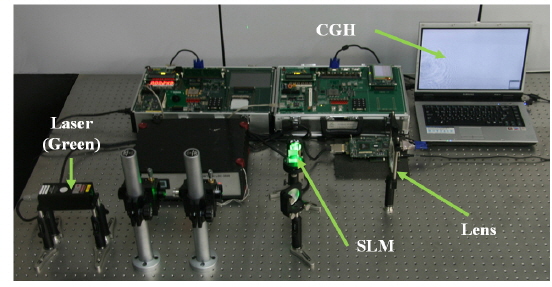
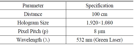
The resultant holograms were displayed with the optical equipment and reconstructed in the S/W for testing. Figure 11 shows the optical system employed, and the experimental parameters are listed in Table 4. The system consisted of a reflective SLM, a green laser with the wavelength of 532nm, and optical elements. The SLM had the resolution of 1,920×1,080, with the pixel pitch of 8 μm.
[TABLE 4.] Parameters for the experiment

Parameters for the experiment
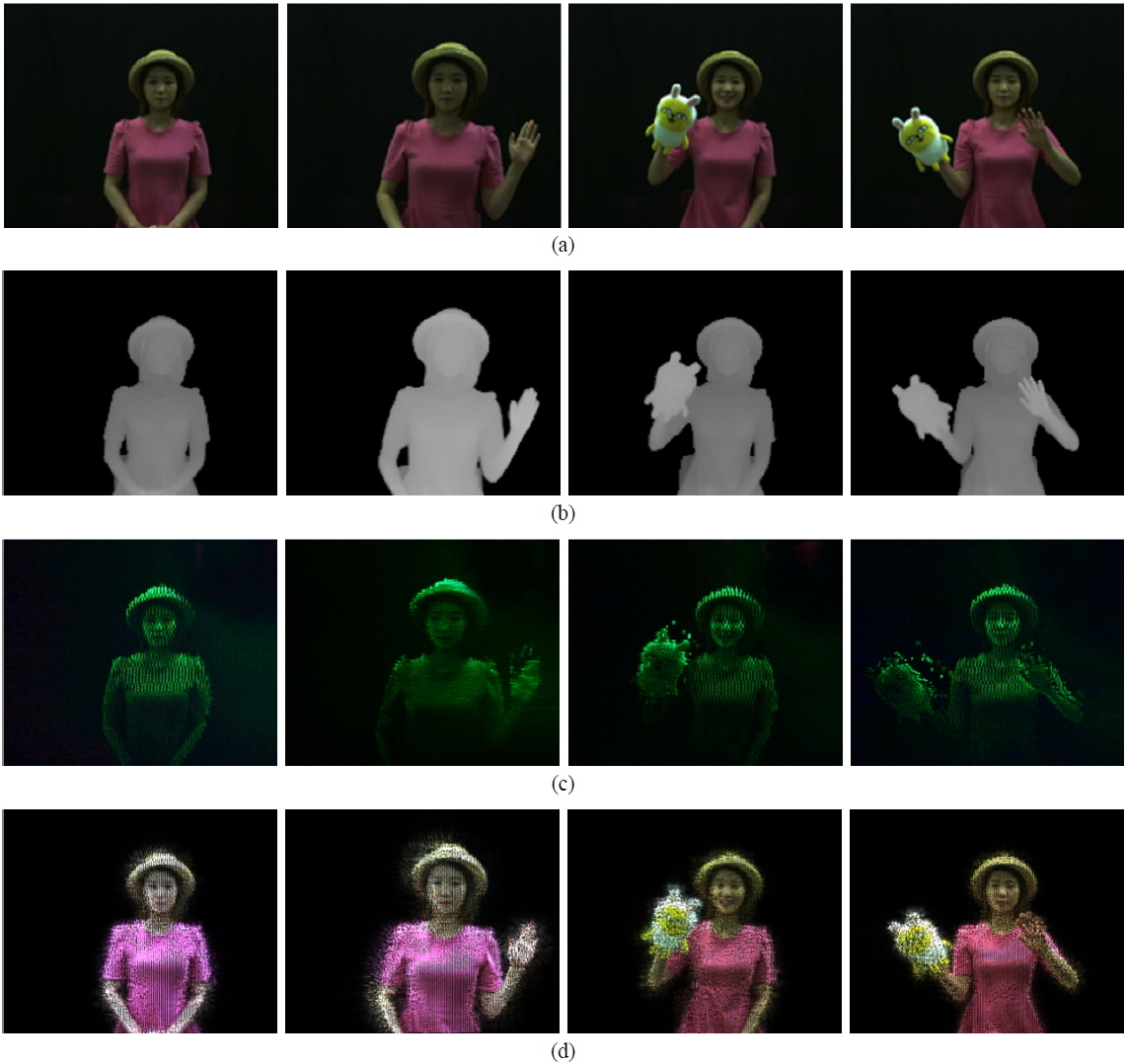
The captured images of the visual display are shown in Fig. 12. Figure 12(a) and (b) show the captured RGB and depth image. The depth image had the spatial resolution of 176×144 and the depth resolution of 255. Our research team does not have a color holographic display, so the hologram was optically displayed using a green laser. Figure 12(c) shows a captured image of the optical reconstruction, which was generated from gray information of the RGB image and depth information. The optically reconstructed region depended on the range of the depth camera, which covered from 0.5 m to 5 m. However, the S/W reconstruction used all three lasers, allowing reconstruction of the color hologram. Figure 12(d) shows the S/W reconstruction results. The S/W reconstruction was carried out to test the hologram, and the results were treated as 2-D images. The hologram could be reconstructed at a certain distance. After setting the reconstruction distance, the 2-D image was obtained on a plane at the predefined distance. Fresnel transform was used, which is defined in Eq. (5) [17].
[FIG. 12.] Visual results; (a) RGB, (b) depth, (c) optical capturing, and (d) S/W displaying images.

We developed a high-performance CGH using multiple GPGPUs. After optimization with holographic pixel-based parallelization of CGH, object point tiling for multiple GPGPUs, constant memory usage, 4×4 tiling of the hologram, 10:1 CGMA ratio, and 1D/2 Banks memory mapping, CGH was implemented with a holographic video system which consisted of an RGB+depth camera, a cold mirror, and 8 GPGPUs with 2 cores. All S/W was integrated with the LabView S/W. In this system, 6K object points were converted to a full HD hologram with the operation time of about 27ms. We plan to research and develop a system for next generation digital holographic broadcasting and television.