An enhanced 360-degree integral-floating three-dimensional display system using a hexagonal lens array and a hidden point removal operator is proposed. Only the visible points of the chosen three-dimensional point cloud model are detected by the hidden point removal operator for each rotating step of the anamorphic optics system, and elemental image arrays are generated for the detected visible points from the corresponding viewpoint. Each elemental image of the elemental image array is generated by a hexagonal grid, due to being captured through a hexagonal lens array. The hidden point removal operator eliminates the overlap problem of points in front and behind, and the hexagonal lens array captures the elemental image arrays with more accurate approximation, so in the end the quality of the displayed image is improved. In an experiment, an anamorphic-optics-system-based 360-degree integral-floating display with improved image quality is demonstrated.
Integral imaging is a well-known three-dimensional (3D) display system that generates a two-dimensional (2D) elemental image array (EIA) from a real or virtual 3D object, and displays a full-parallax, continuously viewable 3D image based on the generated EIA. A few drawbacks are present in the displayed 3D image, such as limited viewing angle and resolution, owing to the use of a lens array. Also, an improvement in any viewing characteristic affects the others [1-4]. A lot of research has been conducted on solving the problem of narrow viewing angle; however, the obtained results are still limited [5-11].
Horizontal parallax-only volumetric light field display allows the display of a 3D image in a 360-degree viewing zone by using high-speed projection and a rotating screen [12, 13]. A 360-degree integral-floating display (IFD), which is a combination of integral imaging and a light field display, was proposed to improve the limited viewing angle of integral imaging display in the 360-degree horizontal direction [14]. However, the vertical viewing angle is certainly narrow, owing to a function of the double floating lenses, and it presents a low-quality image. These drawbacks occur even in other 360-degree IFDs [15, 16].
Thereafter, a method to enhance vertical viewing angle using an anamorphic optics system (AOS) was proposed [17]. Here, an AOS, which is a vertically curved convex mirror, improves the viewing angle enough for comfortable viewing in the vertical direction, because the AOS disperses reflected light rays more widely in the vertical direction, and during the rotation creates a 360-degree viewing zone in the horizontal. The theory was verified by optical experiment and yielded an efficient result for the enhancement of vertical viewing angle. By controlling the radius of the AOS, the vertical viewing angle can be improved and adjusted as a user wants; however, the low image quality did not change at all.
In this paper, we suggest a method to enhance image quality for a 360-degree IFD using a hidden point removal (HPR) operator and a hexagonal lens array (HLA). With the proposed method, the generated EIAs are absolutely aligned with the HPR operator and the HLA, and the improvement in the quality of the displayed image is appreciable and verified in experiment.
II. AOS-BASED 360-DEGREE IFD USING HPR AND HLA
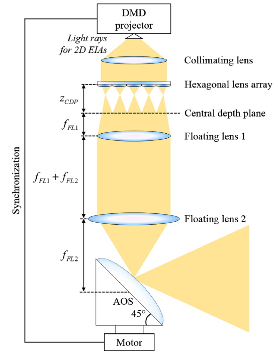
The main process of the 360-degree IFD system is shown in Fig. 1. A collimating lens relays the projected 2D EIAs via high-speed digital micromirror device (DMD) to a lens array, which directly reconstructs them in 3D perspectives. The initially reconstructed 3D perspectives are conveyed to the rotating convex mirror through double floating lenses configured as a 4-
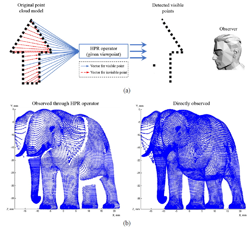
The EIA generation process is the most essential part of the proposed display. Since the problem of narrow vertical viewing angle has been solved by using an AOS, we focus on improving the quality of the displayed image. The resolution of the EIAs is fixed at the DMD resolution, so image quality must be raised without altering the EIA resolution. In our consideration, the duplication of object points that are located behind and in front from each viewpoint is a big factor in the low quality of the displayed image, so the overlap problem of points in the 360-degree IFD must be elucidated. A recently reported HPR operator that determines the points appearing from a given viewpoint [19] can be used to solve the overlapping points problem and is required for the EIA generation process of the proposed system. First of all, the HPR operator extracts only the visible points of the chosen point cloud object and eliminates duplication of the front and rear points for each angular step of the AOS. In other words, when the AOS is in the first position (has not rotated), the visible points are detected through the HPR operator and carried over to the next stage of the EIA generation process. After the first EIA has been generated, the AOS is rotated by a given angular step, and the viewpoint is also shifted by that angular step of the AOS in the horizontal direction. Here another set of visible points is extracted for the corresponding shifted viewpoint, and a second EIA is generated based only on the newly detected visible points. The generation process for every EIA proceeds in this way. Figure 2(a) shows the procedure of the HPR operator that detects the visible points of a point cloud object in our proposed 360-degree IFD system, and Fig. 2(b) shows an example of the extracted visible points from a given viewpoint, comparing it against the case without using the HPR operator, where the viewpoint is fixed corresponding to the center of the object, located at (
Using these corresponding visible points, the reflection from the AOS is calculated based on the coordinates of the visible object points for each viewing direction, considering the AOS angular step, and the coordinates of the corresponding points of the initial 3D perspectives are computed through the double floating lenses. When the extracted visible points are relayed to the central depth plane of the lens array system, the elemental images are generated with hexagonal grids for the chosen HLA specifications, via the conventional integral-imaging pickup process. Recently, several researchers have reported that an HLA improves the image quality of the observable integral imaging display, because hexagonal grids have a better fill factor and provide more accurate approximation, compared to rectangular grids [20-22]. The theory has been verified by experimental results showing that the HLA successfully improves the quality of a displayed 3D image. Also, the number of point light sources has a fundamental influence on the quality of the displayed image: a greater number of point light sources enhances image quality [23-25], where the hexagonal lattice includes more lenses compared to a rectangular lens array, as the distance between point light sources is shorter in the HLA case. Because of these issues have already been certified experimentally in prior research, we simply decided to use an HLA due to its benefits, and applied it in the proposed 360-degree IFD system. Especially, when reconstructing the 3D image using an HLA, empty spaces occur much less often between the balls which are the light rays sampled through each elemental lens, because the hexagonal grids tesselate and fill a plane almost without gaps. In the case of a rectangular lens array, these empty spaces occur severely and a lot of flipped rays may captured.
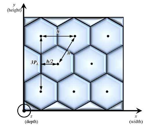
The sampling step for the HLA is much more complex than for a rectangular lens array, as shown in Fig. 3, in which
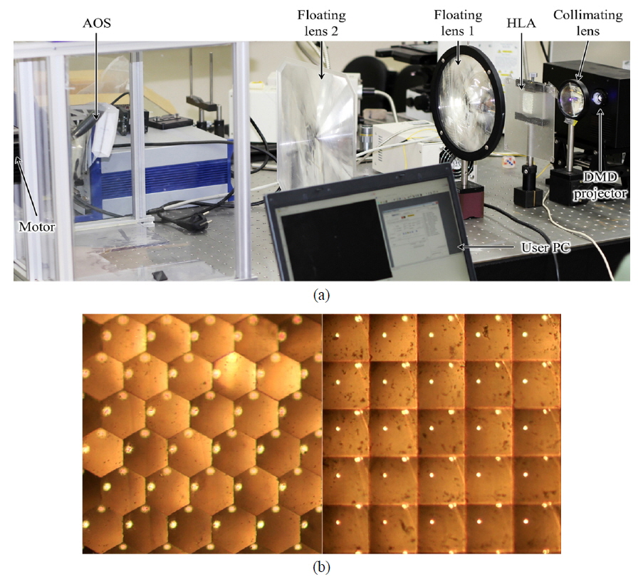
Figure 4(a) shows the experimental configuration. The schematic configuration of the proposed system, illustrated in Fig. 1, is laid out on an optical table. The DMD projector (12-degree tilt, 1024×768 micromirrors), a collimating lens (
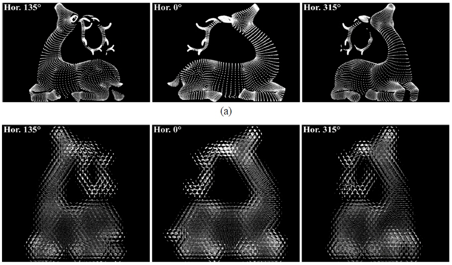
The 3D point cloud model “Lying deer” with 16,000 points was chosen as the object for the experiment. The proposed system displays and tailors 200 different 3D initial perspectives per revolution of the AOS, which is rotated with an angular step of 1.8 degrees. Examples of the generated EIAs for the corresponding viewpoints are shown in Fig. 5. The representations of the point cloud object shown in Fig. 5(a) are only the visible object points, determined using a HPR operator from multiple viewpoints, while the EIAs presented in Fig. 5(b) are generated by the visible points for the corresponding viewing directions. Due to the transformation properties of the AOS, the size of each generated EIAs is expanded by a factor of approximately 1.3 times in the vertical direction, compared to the original vertical size of the object.
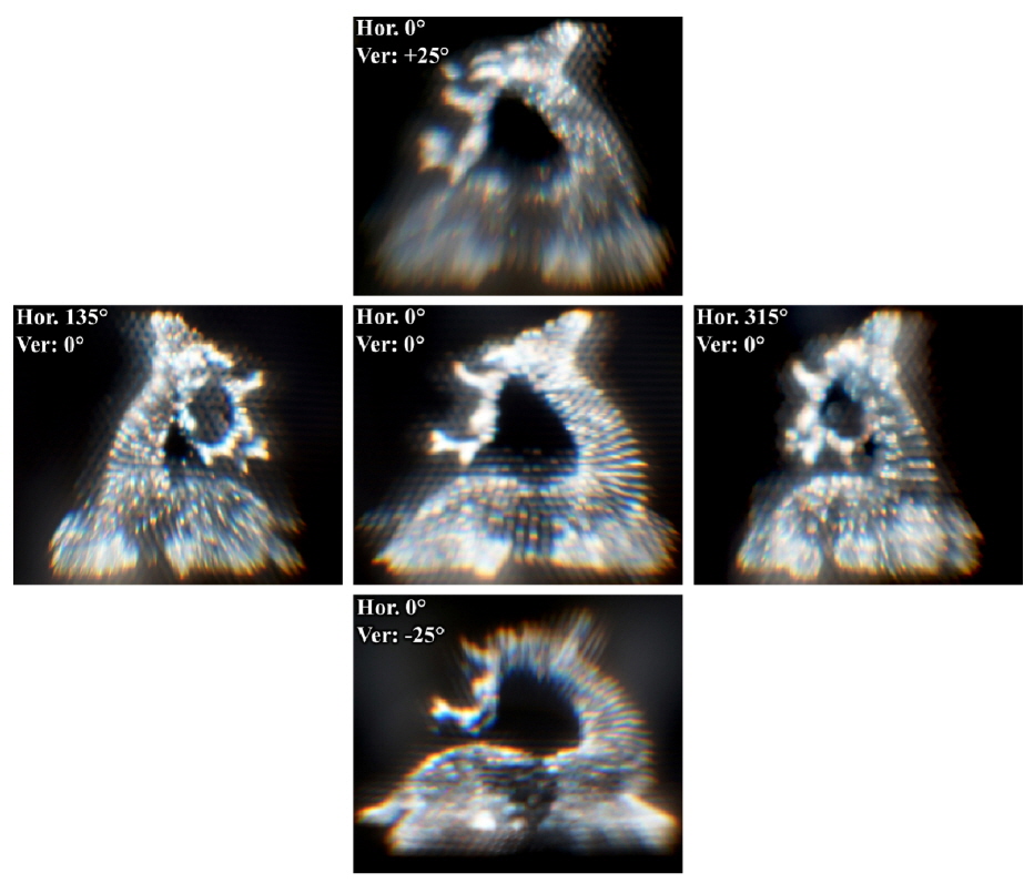
The 3D image on the AOS from multiple viewpoints is presented in Fig. 6, where the size of the displayed image is approximately 62×65 mm. Compared to the image from the conventional 360-degree IFD, the quality of the image displayed on the AOS is obviously better. Here, the displayed image indicates clearly which side of the point cloud object is displayed in the corresponding viewpoint, due to the HPR operator having eliminated the overlap of points. Also, the spaces between points are observed, so the displayed image becomes closer to the original point cloud object. The features of the previous 360-degree IFD, such as 360-degree viewing zone and wide vertical viewing angle, are completely retained. To present a 360-degree viewing zone, we captured the images from 0/360, 135, and 315 degrees. The vertical viewing angle of the displayed image was approximately 50 degrees; this is sufficient for comfortable viewing and makes it possible to further enhance the vertical viewing angle by controlling the focal length of the AOS.
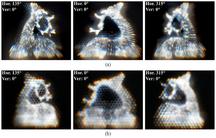
Figure 7 shows a comparison of the image quality for the cases with and without the use of an HPR operator. From Fig. 7(a) it is easy to see exactly which side of the object is appearing from multiple viewpoints, due to the use of an HPR operator. However, in Fig. 7(b), the front and rear points of the point cloud object appeared as overlapped spots, because we did not use an HPR operator, and it affects the image quality greatly: The displayed image is blurred and white overall, due to overlapping points, and seems unfocused. This comparison indicates that eliminating the overlapping points is a very important factor in the enhancement of image quality. Therefore, we see that an HPR operator improves the quality of the displayed image significantly.
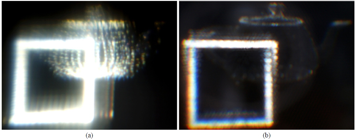
Figure 8 shows a comparison of the cases using an HLA versus a rectangular lens array for the same object: Fig. 8(a) shows the 3D image displayed in the conventional case, while Fig. 8(b) shows the 3D image displayed through an HLA from the HPR-operator-based EIA. Figure 8(b) seems slightly darker than Fig. 8(a), because the HPR operator has extracted only the visible points for the corresponding viewpoint, and the visible points and empty spaces between points are exactly revealed, while in the conventional case the image is bright because more points appear, as seen in Fig. 8(a). Also, a clearer 3D image without flipping is displayed, due to the HLA. From this comparison, it is successfully verified that the HLA reconstructs more accurate 3D images for the 360-degree IFD system and provides higher display density.
In this paper, we propose an enhanced system for an AOS-based 360-degree IFD. Up to now, the 360-degree IFD system has demonstrated a natural full-parallax and continuously viewable 3D image with a wide vertical viewing angle in a 360-degree viewing zone, but the displayed image quality has been the main problem, where the resolution of the EIA is limited by the DMD resolution. Use of an HPR operator and an HLA improve the displayed image quality very well. The HPR operator determines only the visible points of the given point cloud model for each angular step of the AOS and thus removes the problem of overlapping points, so it is a very important factor in the enhancement of image quality. The EIAs are generated by the determined visible points for each viewpoint and captured through the HLA. The HLA has also the important function of increasing the displayed image quality, by providing a more accurate approximation and high sampling density to the display. The combination of the two techniques displays the precise views of the object from every viewpoint. So, the image quality of the 360-degree IFD system is visibly enhanced in experiment, while the previously improved 360-degree horizontal and wide vertical viewing angles are completely maintained.