When the magnitude of gravity applied to an object on the ground is defined as 1 G, microgravity refers to the magnitude of gravity corresponding to 10-6 G, which is quite close to zero gravity. Microgravity is experienced in a typical space environment. Due to its environmental effects, space experiments and space research must be performed using specialized equipment designed for use in microgravity. There are methods by which to generate microgravity on the ground temporarily (e.g., drop-towers, parabolic flight, sounding rockets). The use of drop-towers or parabolic flight generates microgravity primarily through free fall towards the center of Earth, and this condition is utilized for a variety of uses (e.g., tests of space experiment, basic science research, and educational experiments). In the drop-tower method, test equipment is dropped freely from the top of the drop-tower to simulate microgravity. It is widely used worldwide since it is inexpensive and the test process is simple; however, the duration of such experiments is limited to less than ten seconds. The status of drop-towers operated abroad is described in Table 1. Parabolic flight establishes a free-fall condition when an airplane drops freely with constant acceleration toward the center of the Earth, while simultaneously traveling at constant speed in a horizontal direction, thus following a parabolic trajectory. Hence, it temporarily simulates microgravity conditions in the airplane. The duration of parabolic flights is longer than for drop towers (about 20 s), and the magnitude of the simulated gravity can be controlled, though the cost of such experiments is rather high. As shown in Table 2, parabolic flights operate commercially in USA, Russia, Europe, Japan, and China. Sounding rockets are similar to parabolic flights in principle, but sub-orbital flights at higher altitudes substantially extends the duration of experimental simulation of microgravity (3–15 min).
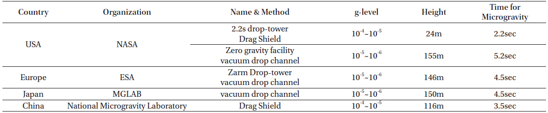
Drop Tower Status
[Table 2.] Parabolic Flight Status

Parabolic Flight Status
The International Space Station (ISS) is a complicated and very expensive facility to operate, but it provides constant microgravity for experiments and other research. Space experiments utilizing the ISS have been performed by those countries with advanced space technology. The ISS program was started in 1998 and the facility was completed around 2010. Its operation is currently planned to extend to 2025. The USA (NASA), Russia, Europe, and Japan still provide budgets of a few billion dollars for the ISS program. The first Korean astronaut, Dr. So-yeon Yi performed 18 space experiments and space missions while in the Russian module of ISS in April of 2008. The ISS plays the role of test-bed for the verification of science technologies in various areas of biology, medical physiology, basic science, materials, and education. In the ISS, investigations related to basic science and material science are performed, as well as research on the development and testing of new materials and space technologies. Specifically, in preparation for the age of space exploration, research is being done to determine the physiological effect of the microgravity environment on humans, and to find solutions to the risks to astronauts inherent in long-term space flight. To this end, through cell and tissue culture, research is performed on biological processes under microgravity conditions. In general, it is known that muscle atrophy and deterioration of the skeleton occur due to microgravity, and that the immune and cardiovascular systems are affected due to the disruption of human biorhythms caused by microgravity.
In order to perform experimental cell-culture experiments under microgravity conditions on the ISS, an automated bioreactor was designed, and a functional prototype constructed. As described in Section 1.1, numerous biological experiments are performed on the ISS to investigate the conditions of, and impacts from, having astronauts in space, using cell-culture experiments. Previously, bioreactors developed in other countries were used for such cell-culture experiments in Skylab and the Mir space station. As shown in Table 3, researchers from several countries (e.g., USA, Europe, Japan) have also performed cell-culture experiments in the ISS, for which many bioreactors have been developed outside of Korea.
[Table 3.] Bioreactor Status in the ISS
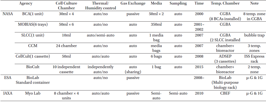
Bioreactor Status in the ISS
When astronauts are exposed to microgravity for a long time, they experience considerable muscle atrophy. Hence, a joint research project was proposed by scientists of Korea and Japan, aimed at preventing muscle atrophy and expediting muscle restoration of astronauts who perform space exploration and space missions in microgravity. During this research, a bioreactor was proposed to use in culturing rodent muscle cells, for use in space experiments aboard the ISS.
The first part of the present study was to review and analyze the scientific requirements and system requirements of bioreactors suitable for such experiments. From this work, a new design was proposed. This reactor enables automated cell culture of 32 samples simultaneously, which is more than the number possible in previous cell-culture experiments in the ISS. It also has the capacity for automatic control of temperature and humidity, and for passive circulation of air, all of which are necessary for cell culture. In this reactor, the cell culture media are circulated in a closed loop to supply nutrients to cells. Because bubbles in the media are problematic, a de-bubbler unit was added to the design. Moreover, the culture-medium circulation module was designed to be replaceable. This makes the same device usable for subsequent cell-culture experiments, and thus improves the cost effectiveness of the design. In order to verify the performance of the bioreactor design, a ground model was built. Using it, the temperature and humidity control, culture medium circulation, culture medium circulation rate to the cell culture chamber, as well as system operation and safety precautions, were all tested and analyzed.
2. DESIGN OF CELL CULTURE BIOREACTOR AND CONTROL SYSTEM
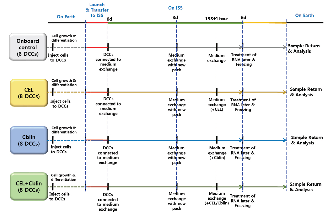
In order to accomplish a successful space experiment, effective procedures are necessary to launch the test equipment and cell sample, to conduct the experiment in microgravity, and to recover the samples resulting from the experiment. As shown in Fig. 1, the space experiment proposed in this study involves the culture of muscle cells from a rodent cell line (L6), under four distinct test conditions: Reference, CEL medication, Cblin medication, and CEL + Cblin medication. The results from these are to be compared and analyzed in relation to muscle atrophy. For each test condition, eight cell samples are cultured; hence, 32 cell samples have to be cultured at the same time. Bioreactors provide the environmental conditions required for cells to survive and grow. They also must be configured with the structure and functions needed to satisfy both mission requirements and system requirements of the test set-up on the ISS, as indicated in Table 4.
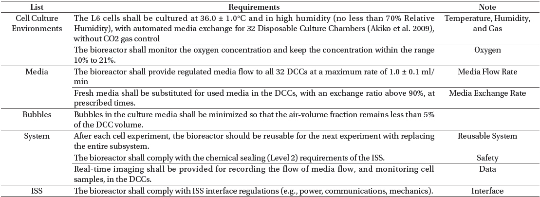
[Table 4.] Top Requirements for Cell Culture Experiment in the ISS

Top Requirements for Cell Culture Experiment in the ISS
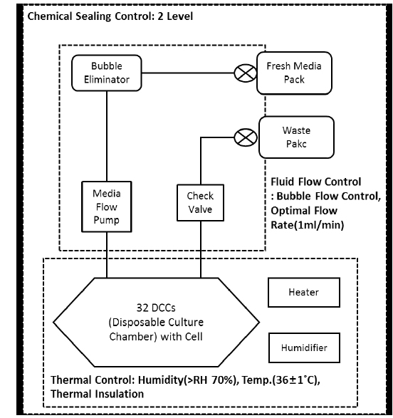
In order to meet the requirements mentioned above, the bioreactor had to be designed with a focus on continuously maintaining the conditions required for the survival and growth of the muscle cells, in microgravity. At the minimum, this means providing for forced convection, changes in temperature and humidity, and periodic circulation of culture medium to supply nutrients. Overall, the functional model of this newly designed bioreactor had to be capable of temperature control, humidity control, circulation of culture medium, chemical sealing, and thermal insulation, as well as providing flexibility for replacement of expended culture medium, and replacement of the entire cell culture chamber (module) after each experiment. Moreover, because bioreactors are vulnerable to contamination of the cell cultures and culture media, the design needed to include replaceable culture-medium-circulation modules, in order to extend the useful life of the remainder of the bioreactor. It was also designed to enable the circulation of culture medium to 32 culture chambers at a maximum speed of 1 ml/min, while it automatically maintained the temperature of the reactor at 36±1°C and the relative humidity at 70%. A de-bubbler device to eliminate bubbles in the culture media was also proposed. Fig. 2 displays the basic concept of the bioreactor proposed in this study.
In order to meet all the requirements mentioned earlier, the bioreactor comprised five modules for: 1) cell culture, 2) fluid flow control, 3) supply of culture medium, 4) electronics, and 5) structure.
A cell-culture module consists of 32 DCCs (Disposable Culture Chambers; Akiko et al. 2009) that each contain cells for culture, a heater for temperature control, thermal insulation to prevent dew at a given temperature and humidity combination, a humidity-control instrument, a camera to record environmental data, and sensor for temperature and humidity. The temperature-humidity control unit consists of a heater for temperature control, thermal insulation film attached to the surface of the cellculture module, a small DC fan to circulate warm air, and a water tank to raise humidity. Heat generated by the heater is conveyed to the whole cell-culture module by a small DC fan, and a water tank in front of the heater is exposed to the warm air constantly to evaporate water and raise the humidity within the cell-culture module. Based on the command signal received from the main controller, all these processes are controlled by the temperature-humidity controller to achieve and maintain the target temperature, through feedback from temperature-humidity sensors installed in two locations on the cell culture module. A built-in CMOS camera in the cell-culture module enables taking digital images of the inside of the DCCs. Thus, it is possible to monitor and store visual data concerning the generation and introduction of bubbles in the media, which obstruct muscle cell culture.
There are four sets of fluid-flow-control modules and each module comprises pumps to supply cell-culture media to the 32 DCCs, a de-bubbler unit, and check valves to prevent reverse flow. The circulation of the fluid-flow-control module starts from the medium pack of the medium supply module. Culture media supplied from the medium pack is drawn through a tube by a micro-pump, and then is injected into a multi-port connector divided into eight ports, and past a small check valve to prevent reverse flow back into the pump. Fresh culture media pushed by the pump passes through a tube and a connector again, after which it is injected into a DCC through a needle-like nozzle. In this way, nutrients are periodically supplied for cell culture.
The exhausted culture media passes through a discharge nozzle (installed opposite the input port). Next, it passes through a connector and tube to be fed into a multi-port discharge connector. In this connector, the culture media from eight tubes enter a single, larger tube to be discharged into the medium waste pack.
A fluid-flow-control module comprises eight pumps, eight check valves, a de-bubbler unit for bubble elimination, and a vacuum pump. This module supplies fresh culture media to the DCCs and removes bubbles introduced during the supply process. It also discharges the exhausted culture media. This fluid-flow-control module controls the flow rate of culture media into the DCCs, and is able to set the time and amount of culture medium needed, according to the test requirements during the cell-culture experiment. The electronic module was designed based on the ISS power standard (28 V DC): therefore, 28 V DC power is distributed and supplied to all the power-consuming components: fan, film heater, circular heater, pumps, sensors, all controllers, and all the electronic instruments. After distribution to individual components by the power controller, the power is converted to 24 V, 5 V, or 3.3 V, to satisfy the power needs of each component.
The master controller is the core of the bioreactor and controls the entire system. It commands the sub-controllers (e.g., fluid-flow-control module, cell-culture module, data-processing module, and temperature-humidity module) according to each mission. The master controller is connected to an external PC that controls the cell-culture environment and measures data.
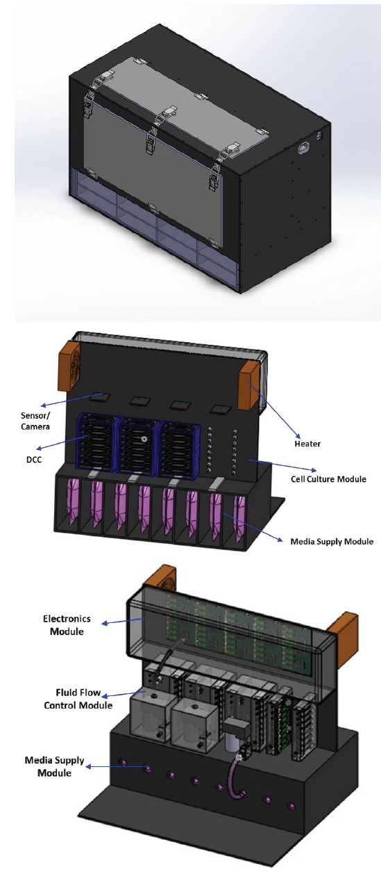
Typically, the equipment of the ISS is transported in standard bags, hence, the bioreactor in this study was designed to meet the ISS 2CTB (double-sized Cargo Transfer Bag) standard. The 2CTB standard restricts the dimensions to 482 mm × 413 mm × 470 mm, and maximum weight below 52.4 kg. Based on the system configuration and size described above, a three-dimensional design of the bioreactor was completed. In this model, the cell culture module was located in the front part of the system, as shown in Fig. 3, and only the cell-culture module was insulated to allow it to maintain a temperature of 36°C and greater than 70% relative humidity. The medium supply module is responsible for supplying and discharging culture media, so it also was configured as a replaceable unit to allow rapid restoration of culture medium supply, medication treatment, and RNA Later treatment to analyze the DNA of the cells for test durations of up to one week. The fluid-flow-control module is located behind the culture-medium-supply module, and connects it and the DCCs with the medium-circulation control. The electronic module is located at the rear of the equipment to control the whole system.
As described in Section 2, the primary functions of the bioreactor were implemented to satisfy the requirements of the cell-culture experiment. The major controls of the bioreactor are managed by the main control unit in the electronic module, and the major controls and their implementation, are as described below.
DC heater surface-temperature control via a built-in thermostat and status feedback to the master control unit DC rotary-fan control of heaters via a PWM driver and status feedback to the master control unit Measurement data (obtained from temperature, humidity, and oxygen sensors) handling CMOS-type camera and LED-back-lit control and image data handling Pump control (both sequential and simultaneous operation control methods for 32 pumps available) and status feedback to the master control unit Vacuum pump control for bubble elimination and status feedback to the master control unit DC cooling-fan control and temperature data handling in the electronics module
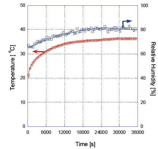
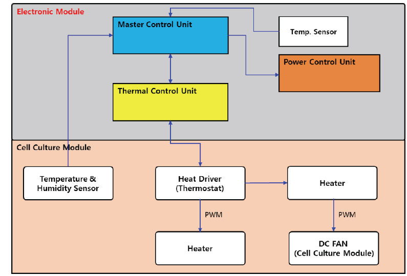
The functional diagram for temperature-humidity control of the bioreactor is shown in Fig. 4. As mentioned in Section 2, using a DC heater, two sets of DC fans, and two sets of humidity control devices containing water, heat generated in the heater is used to adjust the temperature and the humidity through forced convection by DC fans. This controller receives feedback data from the internal temperature-humidity sensors and controls the surface temperature of the heater. In the case of abnormal conditions in the heating system, the main control unit shuts off the power supply of the heat-control unit. Fig. 5 shows the performance test results of the actual ground model of the bioreactor. From this result, it was found that the temperature and humidity could reach nominal for cell culture within ten minutes, using only one set of DC heaters and DC fans. These tests were performed for one week prior to use during the actual test period.
In addition to the functions of controlling temperature and humidity, the other major function of the bioreactor is supplying culture media to the 32 DCCs and discharging spent culture media. Basically, media from the fluid-flow-control module goes through the pump and de-bubbler unit to feed into the DCCs. The used media are discharged through check valves, and there are four sets of these modules. Culture media are supplied to each set through nozzles connected to eight DCC assemblies in the cell-culture module. Fluid-control pumps operate in three modes: a) individual flow control mode, b) sequential flow control mode, and c) simultaneous flow control mode. The individual flow control mode enables control of the flow rate of a specified DCC; however, in order to supply fluid to all the DCCs, the sequential and simultaneous flow-control modes are used. In the sequential flow control mode, culture media are sequentially supplied to all DCCs, one-byone to reduce load and vibration, while in the simultaneous flow control mode, culture media are supplied to all DCCs at the same time.
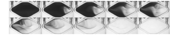
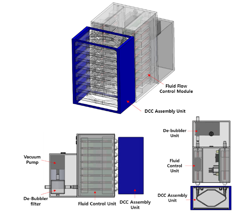
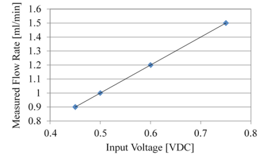
In Fig. 6, a 3-dimensional design of a set of fluid-flow-control modules connected to a DCC assembly is shown. Using the fluid-flow-control module shown in Fig. 6, tests were performed to determine the culture-medium flow rate, rate of exchange of spent with fresh media, and the occurrence of bubbles. Based on the medium flow rate, pump operation in three modes was verified, and a flow rate greater than 1 ml/min was observed to depend on the pump-applied voltage, as shown in Fig. 7. In the DCC medium-exchange-rate test, clean water was fed into a DCC filled with media, and the media discharge process was filmed. Then image processing was performed pixel-by-pixel, and the discharge results for all the DCCs were compared.
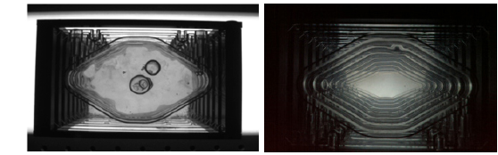
As shown in Fig. 8 (media discharge and exchange photos), the operation of the fluid-flow-control pump enabled the exchange of more than 90% of the spent media with fresh media (in this case clean water) through the DCC inlet port in 10 minutes, and discharged the spent media through the DCC outlet port.
When bubbles contained in the culture media and DCC tubes are carried into the DCCs, they interfere with the cell-culture process. On the ground, when bubbles are formed, they rise up, thus, bubbles do not contact cells on the DCC surface. However, in microgravity, the bubbles could contact cells and obstruct the supply of media to the cells. In order to resolve this, a de-bubbler unit was installed in the bioreactor to eliminate bubbles in the medium-flow tubes using pumps. Fig. 9 shows the picture of units with and without de-bubblers, and the right figure shows that bubbles were eliminated by the de-bubbler unit.
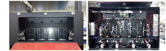
Based on the design described above, the ground model of the bioreactor (Fig. 10) for space experiment was built and functional tests of the bioreactor were performed. Then a cell-culture experiment was performed on the ground to verify the feasibility of the bioreactor.
In this paper, we describe the development of a bioreactor suitable for cell culture experiments in the ISS. Based on the designs of non-Korean bioreactors already developed, and on the requirements for cell culture experiments in space, a new bioreactor design was proposed. It is able to automatically culture 32 samples simultaneously, and has automatic control of temperature, humidity, and culture-medium injection rate.
The medium circulation modules are designed to be completely replaceable in order to reuse the rest of the bioreactor. This designed provides the flow of culture media to 32 culture chambers at the maximum speed of 1 ml/min with bubbles eliminated.
Based on the new design, a ground prototype model of the bioreactor was built to verify the performance of the reactor. A cell culture experiment was performed (on the ground) to confirm the feasibility of this bioreactor.
The design of the reactor and the test results are directly applicable to the development of a flight model for a future joint international space experiment in the ISS. It is also applicable to development of commercial equipment for automation of cell culture experiments that have thus far, been performed manually.