The Accurate Ranging System for Geodetic Observation – Mobile (ARGO-M) was successfully developed as the first Korean mobile Satellite Laser Ranging (SLR) system in 2012, and has joined in the International Laser Ranging Service (ILRS) tracking network, DAEdeoK (DAEK) station. The DAEK SLR station was approved as a validated station in April 2014, through the ILRS station “data validation” process. The ARGO-M system is designed to enable 2 kHz laser ranging with millimeter-level precision for geodetic, remote sensing, navigation, and experimental satellites equipped with Laser Retroreflector Arrays (LRAs). In this paper, we present the design and development of a next generation high-repetition-rate SLR system for ARGO-M. The laser ranging rate up to 10 kHz is becoming an important issue in the SLR community to improve ranging precision. To implement high-repetition-rate SLR system, the High-repetition-rate SLR operation system (HSLR-10) was designed and developed using ARGO-M Range Gate Generator (A-RGG), so as to enable laser ranging from 50 Hz to 10 kHz. HSLR-10 includes both hardware controlling software and data post-processing software. This paper shows the design and development of key technologies of high-repetition-rate SLR system. The developed system was tested successfully at DAEK station and then moved to Sejong station, a new Korean SLR station, on July 1, 2015. HSLR-10 will begin normal operations at Sejong station in the near future.
Satellite Laser Ranging (SLR) system measures the two-way Time Of Flight (TOF) between pulses emitted from laser transmitter of ground stations and pulses returned from Laser Retro-reflector Arrays (LRAs) on Earth orbiting satellites. The start (laser fire time) and stop (return epoch) events from which the TOF is determined are time-tagged with picosecond resolution. This provides range measurements of millimeter-level precision, and this method can be considered to be the most accurate technique currently available for the precise orbit determination of Earth-orbiting satellites with LRAs.
Recently, the development of constituent technologies of SLR to improve SLR system ranging precision has become an important issue. It has common tendencies about kilohertz (up to 10 kHz) systems with higher-repetition-rate lasers, fast event timers, and control & analysis software (Iqbal 2011; Kirchner et al. 2011; Peiyuan et al. 2013; Zhibo et al. 2013). Some of the SLR stations still use Nd:Yag 10-110 Hz laser systems with pulse energies of 20-120 mJ and pulse widths of 50-200 ps. However, following the lead of Graz SLR station, which introduced 2 kHz laser ranging in 2003, several stations are currently replacing their low-repetition-rate (10-20 Hz) with the high-repetition-rate (1-10 kHz) system (ILRS 2015a).
Compared with low-repetition-rate SLR technology, high-repetition- rate SLR offers a large number of possibilities for improving the accuracy and precision of the principal SLR data products (Hausleitner et al. 2010). Specifically, kHz laser systems have greater single-shot precision due to the narrower pulses used, and larger Normal Point (NP) precision due to the greater number of observations. A 10 ps laser pulse width allows a range resolution of 1.5 mm (Seeber 2003). As shown in Table 1, the Graz (Austria), Herstmonceux (England), and Potsdam (Germany) stations are currently operating at high repetition rates.
[Table 1.] Site log of major SLR stations.
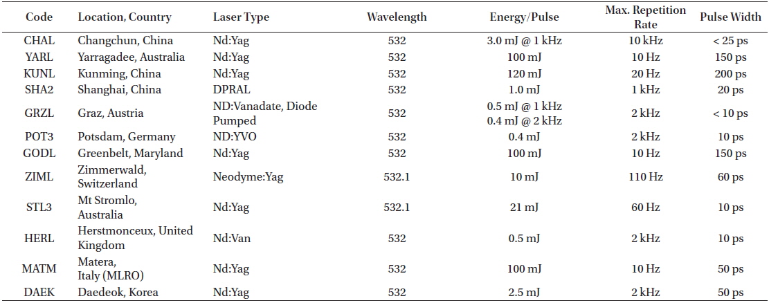
Site log of major SLR stations.
With many advantages, such as increased single shot precision, an improved NP Root Mean Square (RMS), high return rates, and faster acquisition during tracking, the high-repetition-rate approach should be applicable to SLR applications such as International Terrestrial Reference Frame (ITRF), plate tectonics, and time transfer experiments. (Iqbal 2011; Zhibo et al. 2013; Sośnica 2014). In addition, the increased number of range measurements with improved accuracy allows additional scientific data to be obtained for spin determination of geodetic satellites and Precise Orbit Determination (POD)(Lim et al. 2002; Kim et al. 2012). Through application of a kilohertz laser repetition rate, tens of thousands of measurements per pass can be conducted, so as to obtain information on satellite spin parameters (Kucharski et al. 2014).
The 10 kHz Graz SLR system was presented by Dr. Georg Kirchner at an International Laser Ranging Service (ILRS) workshop in 2011, as a means of further exploiting the advantages provided by the high-repetition-rate SLR technique (Kirchner 2011). Dr. Kirchner expects that the kHz laser repetition rate system will be the future SLR standard.
Further, Shanghai SLR station has conducted experiments on the promotion of 10 kHz SLR technology in China (Zhibo et al. 2013), and SLR measurement for ILRS satellites have been successfully implemented using a 10 kHz repetition rate laser. In addition, Changchun SLR station has been upgraded using independent research software and a Range Gate (RG) generator (Liu et al. 2011).
The first Korean SLR system, known as Accurate Ranging System for Geodetic Observation – Mobile (ARGO-M), began first observation operations in 2012. In April 2014, this system was approved as validated station, DAEdeoK station (DAEK), which was validated by the ILRS following a long evaluation process. The DAEK station was operated routinely 2 kHz laser ranging and tracked ILRS satellites with orbit altitudes of 400-25,000 km. The DAEK station ranging performance has millimeter-level precision; this is more accurate than the mean precision value of ILRS stations (Lim et al. 2010; Choi et al. 2014).
This paper focuses on the design and development of a high-repetition-rate SLR system. The developed system incorporates a novel RG generator, real-time control software and data processing software, which allow the TOF to be measured with an increased laser repetition rate.
2. KEY TECHNOLOGIES OF HIGH-REPETITIONRATE SLR SYSTEM
The basic components of an SLR system include laser transmitter, light-detecting receiver, time detector and control & data processing software. Using the predicting orbit tracking information, the departing laser pulses trigger a start epoch time and the reflected laser pulses from the satellite with LRAs are registered as stop epoch time by a sensitive detection device.
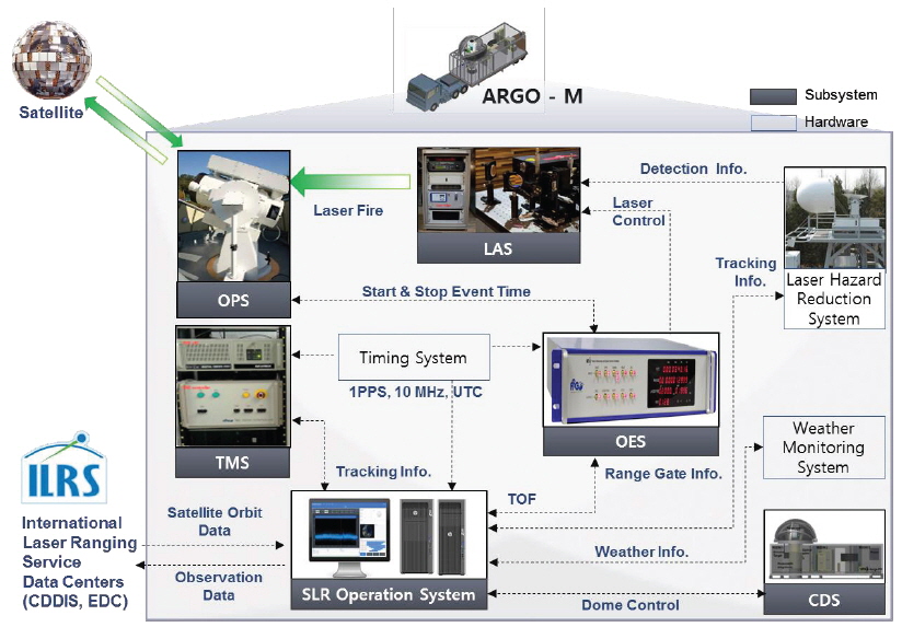
Fig. 1 shows the subsystems of ARGO-M, which were developed based on the modular design concept. The subsystems are categorized based on the functionalities, consisting of the LAser Subsystem (LAS), OPtical Subsystem (OPS), Opto-Electronic Subsystem (OES), Tracking Mount Subsystem (TMS), Container/Dome Subsystem (CDS) and SLR Operation Subsystem (SOS).
The key technology employed in each of these systems was considered in the design and development of the present high-repetition-rate SLR system, which comprises a laser, event timer, new RG generator, real-time control, and data processing software.
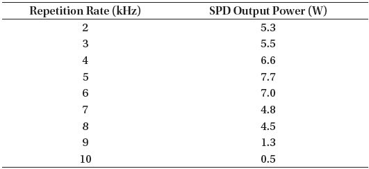
The laser system generates a green laser with an ultra-short pulsed laser for enhanced ranging accuracy. Specifically, the laser system of ARGO-M uses a high pulse energy and high repetition rate picosecond laser, the RGL-532 model manufactured by Photonics Industries. This laser is characterized by its variable repetition rate control and excellent beam quality (M2 typically < 1.2). The main specifications of this laser are listed in Table 2. The Start Pulse Detector (SPD) output powers as various laser repetition rates are shown in Table 3. These data were validated using the same Neutral Density (ND) filter through a digital oscilloscope.
[Table 2.] Specifications of Laser.
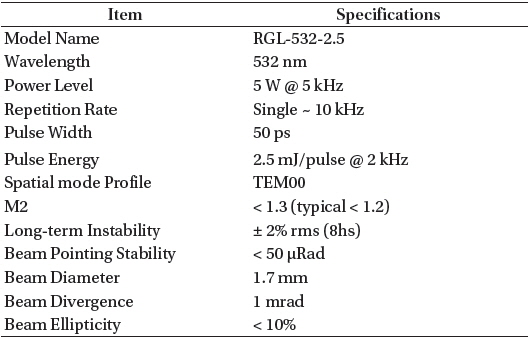
Specifications of Laser.
[Table 3.] SPD output power as laser repetition rate.

SPD output power as laser repetition rate.
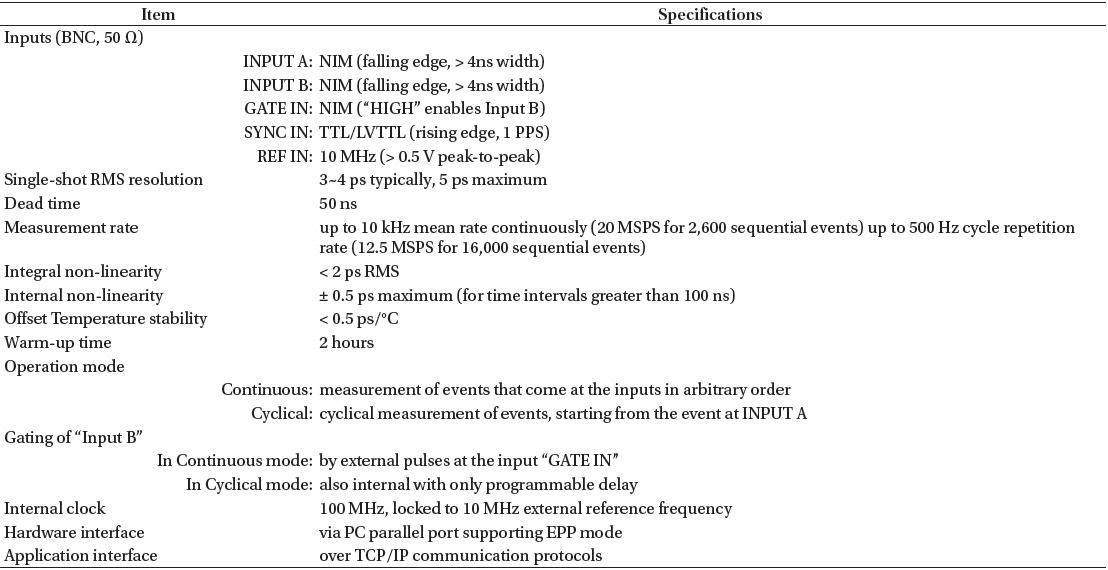
The opto-electronic system plays an important role in measuring the start and stop epochs of laser pulses and also in controlling some devices for accurate range measurement (Jo et al. 2011; Park et al. 2012). In particular, accurate timing is crucial for high accuracy TOF measurements. Currently, event timers are considered to be the most suitable devices for high-repetition-rate SLR system, as they determine laser firing and return epochs independently. ARGO-M uses an A033-ET model of Riga Event Timer, which is a computer-based instrument that measures the time instants at which input events (represented by electrical pulses) occur. Table 4 shows the specifications of A033-ET (Institute of Electronics and Computer Science 2010).
[Table 4.] Specifications of A033-ET.

Specifications of A033-ET.
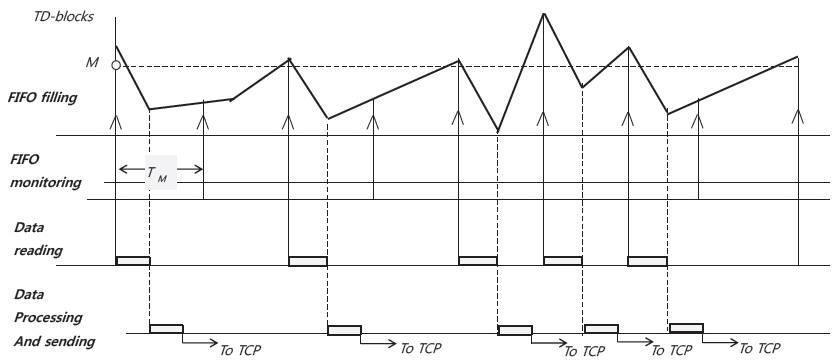
A033-ET has two inputs (A and B) at which events are alternately measured with 50 ns dead time. Epoch time-tags for each measurement appear at the timer output in order of measurement with a 1 ps Least Significant Bit (LSB) resolution. Two basic operation modes are available; continuous and cyclical mode. In the case of the high-repetition-rate SLR system, the continuous mode is well suited for measurement of the overlapped time intervals between the start and stop events, which are obtained as separate A033-ET inputs and in arbitrary order. In continuous mode, A033-ET transforms each input event into a single 64-bit Timing Data block (TD-block) and sequentially accumulates these TD-blocks in a First-In, First-Out (FIFO) buffer memory. When the specified memory state is detected, the control software takes out TD-blocks from the memory. This procedure is repeated cyclically, as shown in Fig. 2. The maximum average rate of continuous measurement is primarily limited by the available reading and processing speed of the TD-block by the control software. In addition, to achieve the optimum measurement accuracy, the event timer should be synchronized with the 10 MHz reference frequency and 1 PPS sync pulses of the Global Positioning System (GPS) time and frequency system.
2. 3 ARGO-M Range Gate Generator (A-RGG)
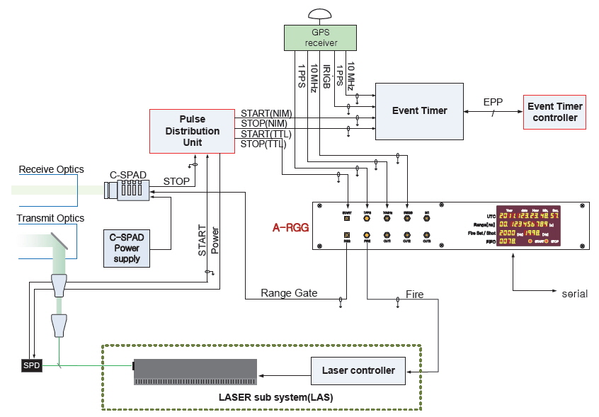
The high-repetition-rate SLR system requires a fast opto-electronic control over both the laser firing signal and the RG signal, so as to Compensate for the Single Photon Avalanche Diode (C-SPAD). The C-SPAD detects photons returned by the satellites within a signal strength range of a single to hundreds of photons (Lim et al. 2011). The laser firing times must be measured accurately in order to determine the return event time to within a few nanoseconds. Also, the RG generator must perform a rapid calculation and activate the detector in front of approximately 100 ns before the arrival of the returned photons. The period of time available for this process primarily depends on the laser repetition rate.
For implementation in a high-repetition-rate SLR system, the Korea Astronomy and Space Science Institute (KASI) has developed a novel opto-electronic controller, called the ARGO-M Range Gate Generator (A-RGG) (Bang et al. 2013, 2014). A configuration diagram of the opto-electronic system using A-RGG is shown in Fig. 3.
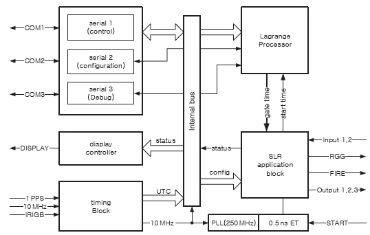
A-RGG consists of a FIRE signal generator, RG signal generator for C-SPAD and three OUTPUT ports to control external devices and the Light-Emitting Diode (LED) indicator, as shown in Fig. 4. The FIRE signal generator controls the laser system to fire laser pulses and conducts laser collision avoidance against backscattering. During high-repetition-rate laser ranging to satellites, overlaps can occur between the fired laser shots and returned photons, and the backscatter due to such overlaps causes significant noise on the C-SPAD. This degrades the observation efficiency. To avoid this problem, the A-RGG stops rather than shifts the laser firing. The period and pulse width of the FIRE signal can be controlled within the 50 Hz - 10 kHz repetition rate using control software. The FIRE period can be set to the number of pulses at 10 MHz for a period of 100 ns. It should be noted that the period setting affects the laser oscillator performance directly.
The RG signal generator generates a laser firing signal on the basis of both the standard frequency (1 PPS/10 MHz) obtained from the GPS time and frequency system and the RG signal for C-SPAD, which is based on the start signal and predicted TOF. The Lagrange processor on the Field-Programmable Gate Array (FPGA) uses 8th Lagrange interpolation to calculate the predicted arrival time of returned photons for given the laser firing epoch within predefined TOFs. To improve the accuracy of calculation, the Lagrange processor utilizes a 1,280 bit divider and micro code method, which performs calculations via a fixed sequence when a START time value is delivered. As a result, the 8th Lagrange interpolation has a calculation time of 65 μs, and the laser fire repetition rate can be controlled at 15 kHz. Table 5 shows the major specifications of A-RGG.
[Table 5.] Specifications of A-RGG.
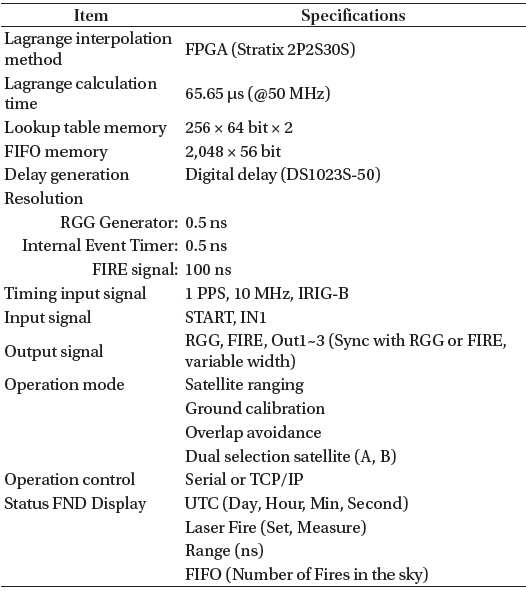
Specifications of A-RGG.
2. 4 High-Repetition-Rate SLR Operation System (HSLR-10)
A next generation SLR operation system for implementation high-repetition-rate SLR system has been developed, which is called High-repetition-rate SLR operation system (HSLR-10).
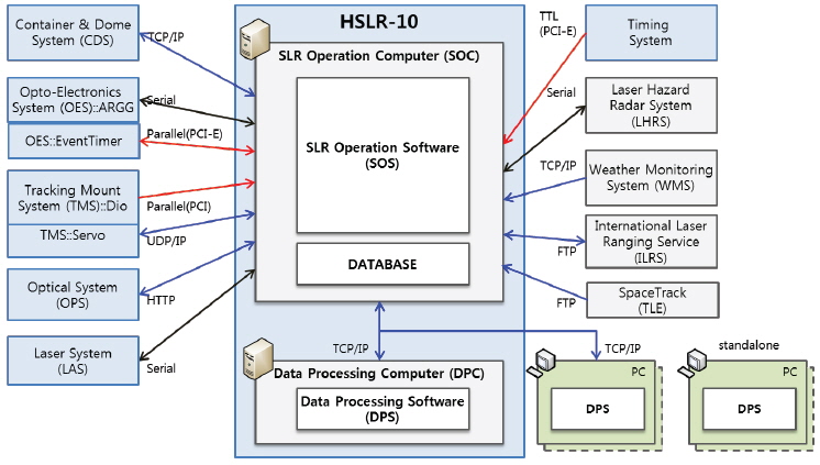
HSLR-10 is composed of two primary parts, which correspond to the two major Central Processing Units (CPUs), i.e., the SLR Operation Computer (SOC) and Data Processing Computer (DPC). To satisfy the real-time processing performance required to facilitate up to 10 kHz high-repetition-rate laser ranging, the SOC and DPC use a high performance workstation with two CPUs, large memory, and a Solid State Drive (SSD). Real-time SLR Operation Software (SOS) and Data Processing Software (DPS) are implemented on each computer. All software implemented in HSLR-10 is written in the C++/C# languages. The operating system used for all HSLR-10 functions was developed based on Windows 7, for operator ease-of-use.
HSLR-10 controls all the subsystems and performs SLR. Therefore, it outputs the final products of the SLR results. In particular, optimal design and compact processing are key for implementation of real-time laser ranging at up to 10 kHz. Fig. 5 is a diagram of the overall HSLR-10 interface. The SOC connects all the hardware interfaces and communicates with the external network. The SOS is installed in the SOC; this software responds to commands from the operator and controls all subsystems. Standalone-type DPS can be used independently, or the DPS can be installed on the DPC. The DPS reads the satellite laser ranging observation data file and generate NP and full rate data from the filtered range data.
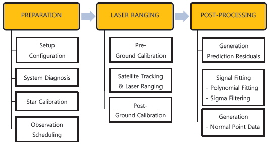
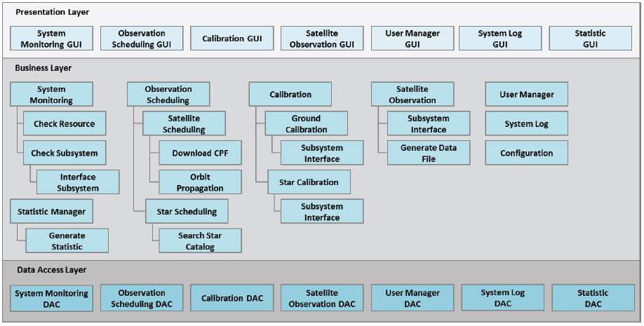
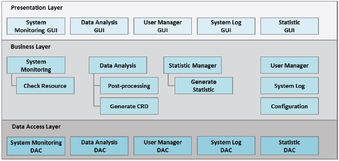
The main functions of HSLR-10 are divided into three steps: preparation, laser ranging, and post-processing, as shown in Fig. 6. The SOS and DPS are based on a layered software architecture including presentation layer, business layer and data access layer. The presentation layer includes the user Graphical-User-Interface (GUI) functions and the control and the business layers are composed of the main functions and control algorithms. The data access layer manages the entire HSLR-10 database, which includes the system log, observation data, and analysis results. Figs. 7 and 8 show the layer architectures of the SOS and DPS, respectively.
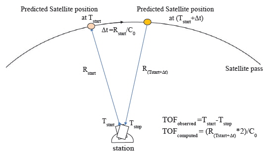
One of the key factors of HSLR-10 is the ranging algorithm for fast RG setting and range combination. The ranging algorithm performs the calculation of satellite orbit prediction and processes the measured event times. The predicted satellite orbit data is generated from Consolidated Prediction Format (CPF) or Two Line Element (TLE). Note that the ranging algorithm calculates the predicted TOF values considering both atmospheric refraction and satellite flight time. The atmospheric correction, which is performed using the Marini-Murray model (Marini 1972), facilitates a coordinate transformation from Cartesian to spherical. An additional correction to the range is then made based on the satellite flight time, which is the period between the laser firing and the arrival of the laser at the satellite. As the satellite continues to move when the laser pulse is in flight, the TOFs for point-ahead and point-behind can differ, from a few milliseconds for Low Earth Orbit (LEO) satellites to a sizeable fraction of a second for GPS satellites and the GLObal NAvigation Satellite System (GLONASS) satellites. In this ranging algorithm, the predicted TOF is computed by considering the point-behind, i.e., the satellite position at the time of reflection, as shown in Fig. 9. For fast RG setting, the lookup table for A-RGG consists of TOF values only, instead of X/Y/Z data, which are transmitted to the A-RGG immediately before the satellite laser ranging. As indicated in the lookup table, the A-RGG calculates the expected laser arrival time using 8th Lagrange interpolation method and controls the C-SPAD.
The processing of the measured event time manages the start and stop event data. The start event processing procedure computes the predicted TOF for a given start pulse event from the event timer and stores it in the memory buffer. When the corresponding stop event occurs, the stop event processing algorithm finds the appropriate start signal in the stored start memory buffer. After calculating the range, the Observed-Computed (O-C) residuals can be determined via the range combination algorithm. HSLR-10 can display these residuals in real time at up to 10 kHz repetition rate processing.
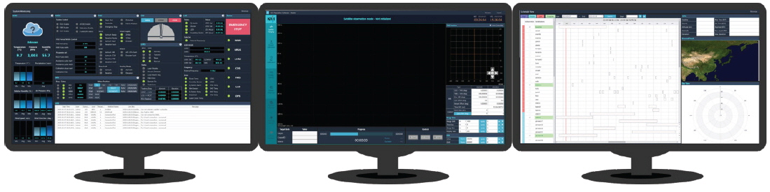
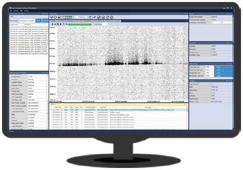
The display of HSLR-10 SOS consists of three parts that are configured by the operator to facilitate observation, namely the monitoring, controlling, and scheduling window. The DPS can be connected to the SOS via direct log-on, and also used as standalone software. The DPS generates the final data product (NP or full rate data) from the observation data for the high-repetition-rate SLR system. The post processing of the range measurements includes calculation of the prediction residuals, removal of large outliers and systematic trends from these residuals, and sigma filtering. Figs. 10 and 11 show the main GUIs of the HSLR-10 SOS and DPS, respectively.
3. INITIAL OBSERVATIONAL RESULTS FOR HIGH-REPETITION-RATE SLR SYSTEM
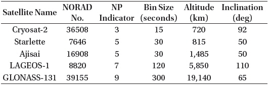
Based on the ARGO-M SLR system, a high-repetition-rate SLR system with the newly developed A-RGG and HSLR-10 was tested at Daedeok station, before being moved to Sejong station. The main functionality for A-RGG and HSLR-10 and system integration testing was conducted at a 5 kHz repetition rate considering the maximum power of the RGL-532 laser. Note that the repetition rate value can be adjusted in accordance with the system configuration of HSLR-10. Experimental SLR tests with a 5 kHz repetition rate were successfully performed for a variety of satellite orbits, as shown in Table 6 (ILRS 2015b). The NP indicators (integers within 0-9) and bin sizes (5-300 sec) differ depending on the satellite orbit.
[Table 6.] List of satellites tracked by high-repetition-rate SLR system.

List of satellites tracked by high-repetition-rate SLR system.
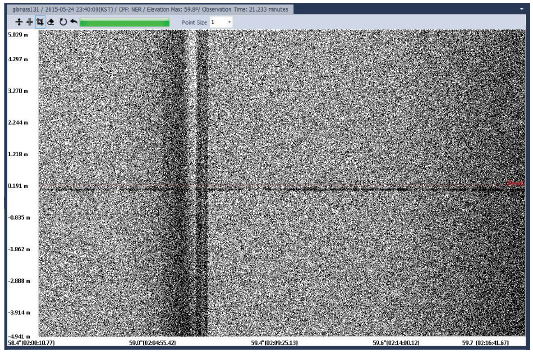
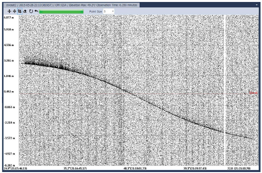
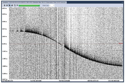
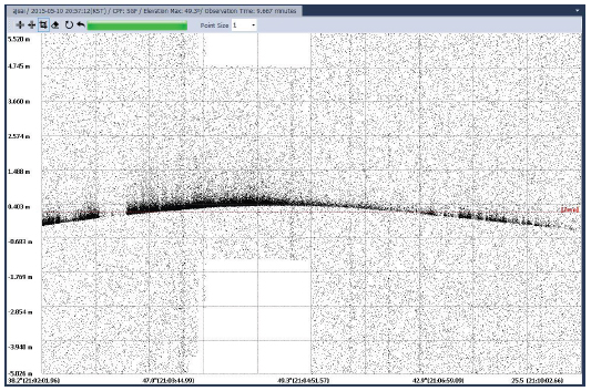
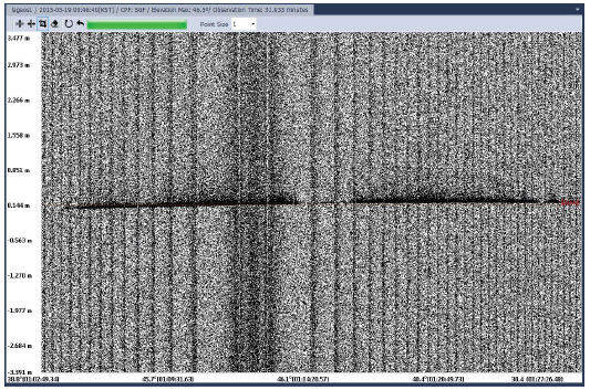
In this paper, representative observational results of the ILRS targets Cryosat-2, Starlette, Ajisai, LAGEOS-1, and GLONASS-131 are shown in Figs. 12-16. These graphs indicate the observation times for the O-C residuals between the measured laser pulse TOFs and the predicted values. These graphs were generated by the DPS of HSLR-10. A higher level of noise compared with that of a low-repetition-rate SLR system is apparent; however, the bold line representing the satellite orbit is clearly visible. In particular, the laser returns between the LEO and GLONASS satellites were successfully obtained. Note that, in actual satellite laser observation, the number of returned photons is influenced by the observation techniques employed by the operator to control the RG, and also by system biases and environmental conditions such as temperature, humidity and pressure.
Compared with low-repetition-rate SLR technology, high-repetition-rate SLR offers a large number of possibilities for improving the accuracy and precision of the principal SLR data products. Improvement of ranging precision through the use of an increased number of returned photons has become an important issue in the SLR field. In this paper, the design and development of a high-repetition-rate SLR system were described, and this system was successfully verified via actual SLR observations from LEO to GLONASS satellites, i.e., Cryosat-2 (720 km altitude), Starlette (815 km), Ajisai (1,485 km), LAGEOS-1 (5,850 km) and GLONASS-131 (19,140 km).
This paper also presented the key technologies in the high-repetition-rate SLR system, along with initial observation results. The primary hardware and software used in this system, A-RGG and HSLR-10, respectively, were newly developed so as to enable laser ranging at up to 10 kHz. These systems can be operated with variable repetition rates, considering the laser output power. The event timer, A033-ET, can conduct continuous measurements at up to 10 kHz in continuous mode. In order to verify the system performance through actual observation, test observations were executed at a 5 kHz repetition rate using a current laser subsystem, namely, the RGL-532 model. The A-RGG successfully generated laser firing signals on the basis of both the standard frequencies from the GPS time and frequency system and the RG signal for C-SPAD, which are based on the start signals and predicted TOFs.
For operation of the high-repetition-rate SLR system, SOS and DPS using a layered software architecture design were implemented in HSLR-10. The main algorithms of HSLR-10, i.e., the real-time control software, ranging algorithm, and data post-processing algorithm, were also verified.
The new high-repetition-rate SLR system will be operated in the new Korean SLR station, Sejong station, which is currently being prepared for this operation. Through use of the developed high-repetition-rate SLR system, it is expected that Sejong station will constitute a leading technological development and make a prominent contribution to the international SLR community.