The lava tubes of the Moon, which were formed by active lava in the past (Oberbeck 1971; Greeley 1971a, 1971b; Cruikshank & Wood 1972; Head 1976), are appropriate for a human base on the Moon (Horz 1985; Coombs & Hawke 1992). Since lava tubes are located below the lunar surface, they protect humans from high energy particles such as cosmic rays without any special shielding equipment, thus avoiding radiation damage (Angelis et al. 2002). Also, lava tubes protect humans from physical impact such as those from meteorites. Since lava tubes are sealed, except for the entrance, the atmosphere is so thin that the conservation of temperature is excellent compared to the lunar surface where there is an extreme diurnal temperature difference.
In previous studies, several places presumed to be the entrances of caves were discovered in the Moon and Mars (Haruyama et al. 2009, 2010, 2011; Cushing et al. 2007; Cushing 2012; Jung et al. 2014). The shapes of these places are similar to the “sink hole” of earth and they have a slightly larger space inside the entrance. Moreover, about 200 pit-looking places, which are known as pit craters (abbreviated to pits), have been discovered and these can be candidates of caves. The pits are found in the regions of the lunar sea and in places that experienced melting due to meteorite impact (Robinson et al. 2012; Wagner & Robinson 2014). Hong et al. (2014) showed that those pits could be entrances of caves through comparing those pits to the actual cave entrance of the Earth.
The Google Lunar X Prize (GLXP) project is a public competition that is planning to explore the Moon using a rover. Among those competitors, Astrobotic Technology Inc. and HAKUTO Team each plan to explore a pit using a rover (Huber et al. 2014; Britton et al. 2015). For both teams, the target landing site is a pit of Lacus Mortis. In this pit, there is a ramp down to the bottom of the crater. Thus, it is believed that the rover could approach the inside of the pit. Although there was a report insisting no evidence of cave entrance structure inside this pit (Wagner & Robinson 2014), all the image data of this pit are shadowed to some portion, the complete shape of pit is not possible to identify. Thus, it is arguable whether there is no inner space.
In this study, a 3D model of the pit in Lacus Mortis was built based on the topographical information obtained from the optical image data of this pit.
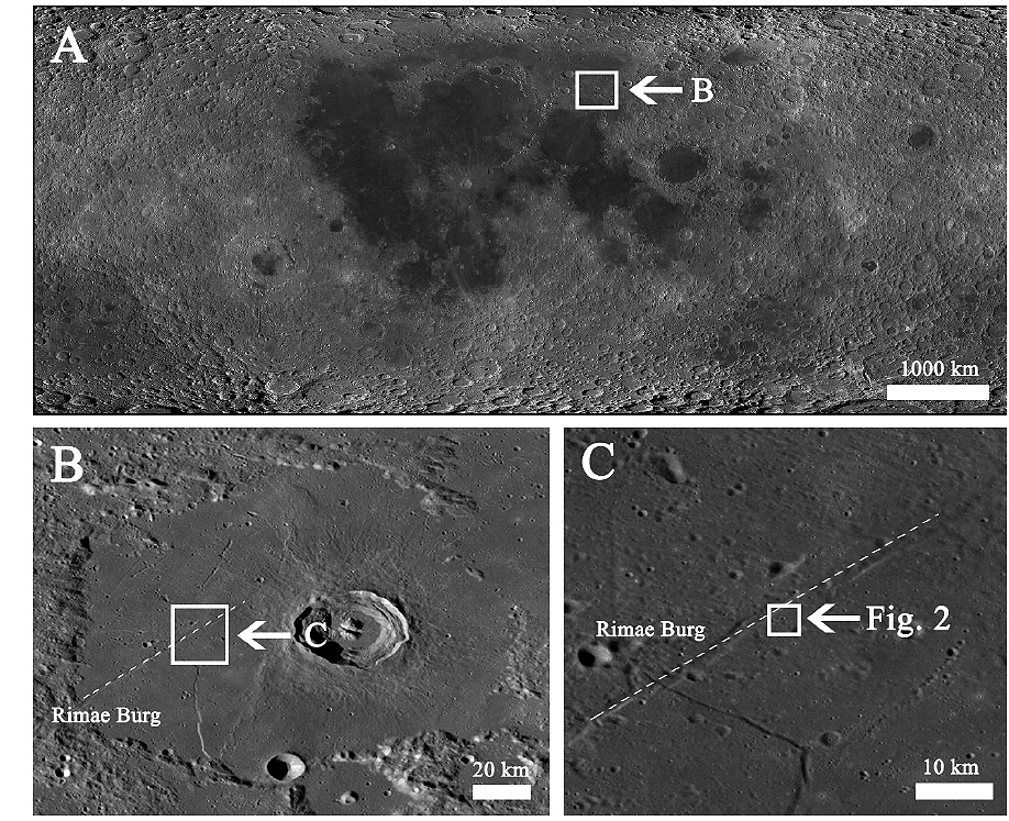
The region of interest, the Lacus Mortis pit, is located at 44.96°N, 25.61°E of Lacus Mortis (Fig. 1). Lacus Mortis is in a lunar mare region and composed of basalt and has several rilles. The pit is located about 1 km away from Rimae Burg. The rilles are in the form of straight line and seems to be a kind of graben. There are pyroclastic deposits which seem to be an evidence of volcanic activity around the grabens(Schultz 1972; Head 1976). Those are believed to be evidences of previous magma activity in the interior of the Moon (Head & Wilson 1993) and lava caves may be in existence there (Greeley 1971b).
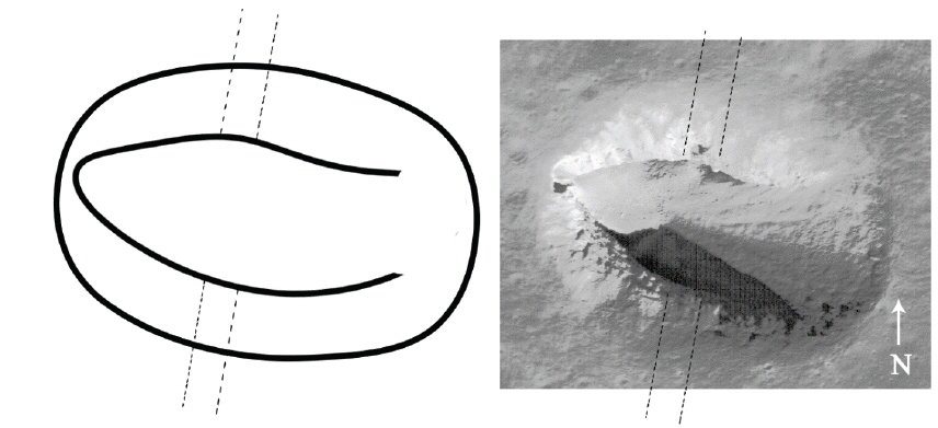
The pit is oval shaped and the length of the major axis is about 260 m while the length of the minor axis is about 100 m. Also, there is a ramp enabling access to the inside of the pit (Fig. 2).
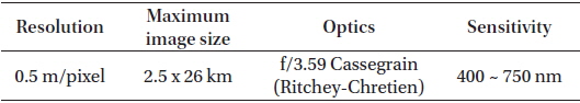
For this study, the optical image data of the Lunar Reconnaissance Orbiter Camera (LROC) from the Lunar Reconnaissance Orbiter (LRO) were used. The LROC consists of two cameras; Wide Angle Camera (WAC) and Narrow Angle Camera (NAC). The Narrow Angle Camera (NAC) has a maximum resolution of 0.5 m/pixel and is suitable for analyzing the topography of the lunar surface. The other information of NAC is listed in Table 1.
[Table 1.] LROC/NAC specification.

LROC/NAC specification.
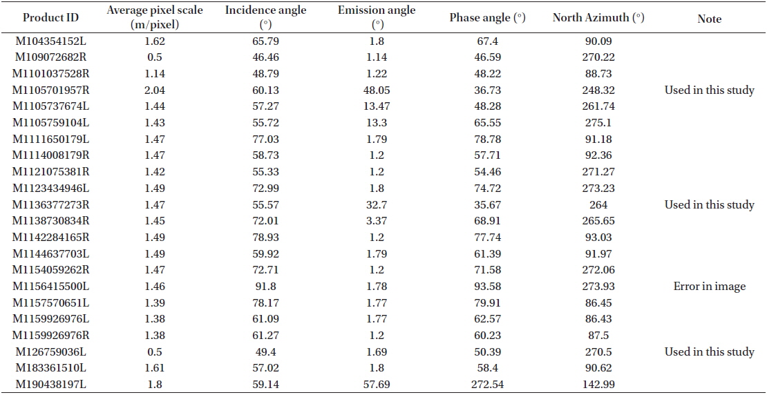
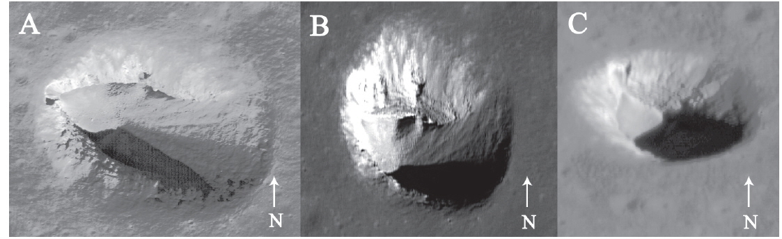
22 images of Lacus Mortis pit are available up to this time and most of them have similar incident angle and emission angle. For this study, 3 of them were selected which seemed to be a best shot and showing different incident and emission angles. The information of 22 images is shown in Table 2, and the 3 images selected are shown in Fig. 3.
[Table 2.] Information of Lacus Mortis pit images.

Information of Lacus Mortis pit images.
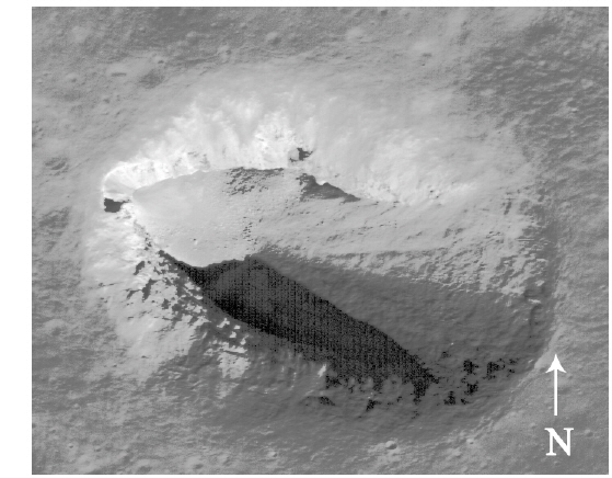
The detailed information necessary to build a 3D model is obtained by analyzing the NAC image data. It is assumed that there is space of a cave across the eastern slope of the pit (Fig. 4). Since the southern shape of the pit could not be identified due to shadows and the interior space of the pit showed be assumed to take any form until the actual exploration on foot and the small shadow in the northern side also indicates that there is a ramp alongside the wall of the pit, it is considered that this ramp could be an entrance to the inside of the pit. Also, since the collapsed ceiling materials covered the floor of the pit, it is assumed that the entrance of the cave was buried or the size of the entrance is much smaller compared to the thickness of ceiling. Thus, the entrance is set to have a small size. Moreover, the big size pits (about 100 m in diameter) discovered up to the present time may have some inner space inside the pit that can be considered suitable for an outpost once the space is excavated slightly more. The existence of inner space is confirmed through the incidence angle of the sun and the emission angle of the satellite. Incidence angle is angle between solar ray incident and normal of planetary surface, and emission angle is angle between satellite camera and normal of planetary surface. Also, there are a few grabens such as Rimae Burg, it is likely that there might be lava tubes below these grabens (Greeley 1971b). Since the pit is not far away from the graben, if there is a lava tube below the surface, the pit could serve as an entrance to this cave. In addition, Astrobotic Technology Inc. and HAKUTO team of GLXP plan to land a rover on this site because there is a ramp on which a wheeled rover could approach the inside of the pit without additional equipment. It looks like the ramp was formed by the collapse of the ceiling, and if we go down the ramp, it is possible to reach the bottom of the pit and explore the inner space. Thus, we have surmised that there is some inner space.
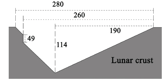
The information necessary to build a model is the length of the major axis, the length of the minor axis, the depth of the pit, the length of the ramp, and the thickness of the crust comprising the ceiling. The information is obtained using the conventional method of measuring the pixel size of various geometrical elements based on the resolution information of image data (Fig. 5). In order to calculate the depth, the end point of the ramp is assumed to be the bottom and the length of the shadow is measured using the following equation (Haruyama et al. 2009):
where
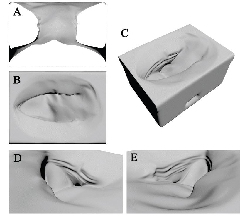
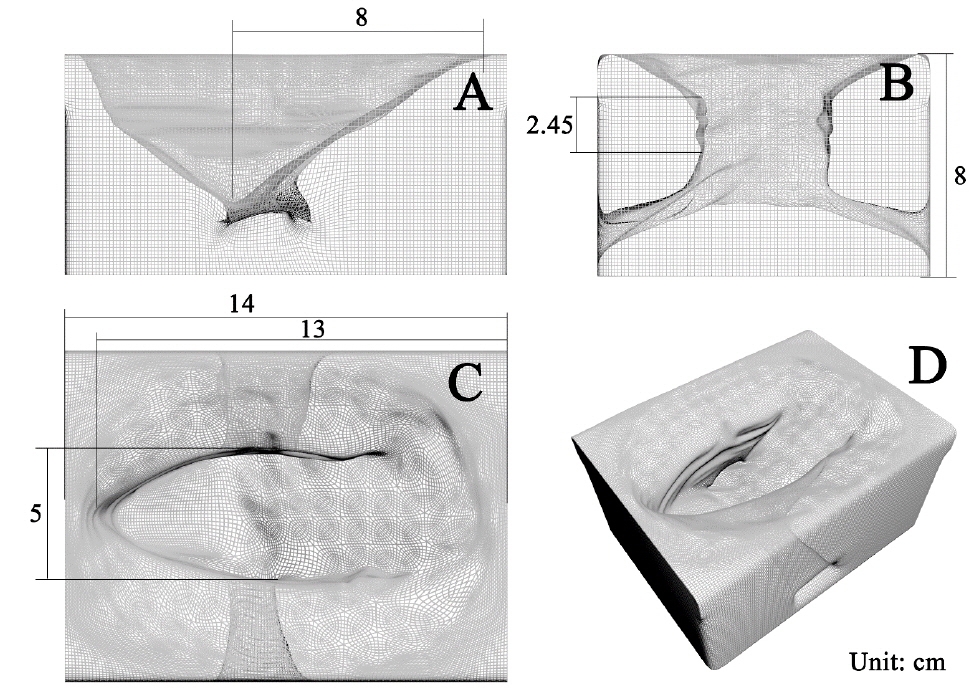
The 3D model rendering was made using 3DS MAX from Autodesk Inc. on a scale of 2000:1. The length of the internal cave in the cross sectional view is 8.6 cm and the height of the internal cave is 3.75 cm. Also, a little bit of tolerance is allowed in each interval of the cave. The reason why the cave is not in a cylindrical shape is due to the assumption that the cave was originally cylindrical, but gradually, the crust material of the ceiling collapsed down to pile up and fill the lower part of the cylinder. If the model covers a larger region that is not limited to the pit, the internal cave will start to have a cylindrical shape that is gradually moving away from the pit.
Each dimension of the model is as follows: the length of the major axis is 18 cm, the length of the minor axis is 5 cm, the depth at the endpoint of ramp is 6.45 cm, and the thickness of the crust at the ceiling is 2.45 cm. There is an unobservable area due to shadow, even when the time of the NAC image data is different. In this case, it was assumed that the model was symmetrical relative to the major axis, and the model was also displayed in various perspectives (Figs. 6 and 7). Also, mesh smooth filtering was applied to express curvatures.
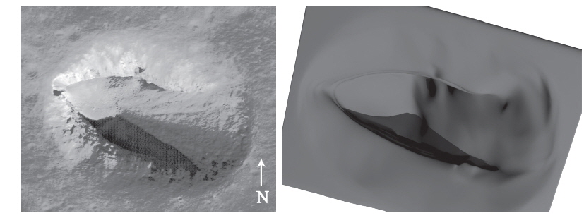
The 3D model built was compared with the NAC image data to find any similarities out similarity with the actual pit. When the viewpoint was set to be consistent with the viewpoint image that resulted from the emission angle of the satellite, it was found that the actual topography was rendered somewhat closely (Fig. 8).
A 3D model was built using the NAC image data of LROC. We assumed that there was a cave in the inside pit based on the existence of graben around the pit and the fact that the bottom area is bigger than the entrance. It was also likely that there are lava tubes below the graben. In spite of this assumption, since the goal was to render actual topography, the model was quite close in achieving the goal.
One of the benefits of this model is that it is based on a computer graphic tool and allows for changes in viewpoint with ease. Hence, we can observe various features of the topography from many viewpoints. Therefore, the observation can be made from a lunar surface viewpoint rather than a satellite viewpoint which can be of great help in pre-planning the rover mission prior to its operation. While this model lacks precision as it cannot render rocks, small hills, and texture of topography, this kind of precision is of little significance in the view of the structure. Therefore, those details can be neglected.
It has been predicted that lunar caves exist, which could serve as a lunar base. A pit was also discovered recently to be a candidate of cave. In order to ascertain the existence of tube-shaped caves inside a pit, it is best to visit the place in person. However, there has been no human mission since the Apollo mission. Thus, there was no way to determine this. Recently, the X Prize foundation and Google Inc. are working together to create the Google Lunar X Prize, which promotes private-funded missions of lunar landings independent of government or research institutes. Ones of the competitors of this project, Astrobotic Technology Inc. and HAKUTO team, decided to have the landing site on the pit of Lacus Mortis, making it a perfect chance to find out if there is a cave inside the pit through direct observation.
In this research, the structure of the Lacus Mortis pit, which is a target landing site of Astrobotic Technology Inc. and HAKUTO team, was investigated and a 3D model was developed. In spite of the assumption that there is a cave inside the pit, the shape of the model is quite consistent with the satellite image data. Moreover, this model allows for various viewpoints. Thus, a lunar surface viewpoint enables us to determine the topography and to have provisions on how to operate an actual rover. In addition, the 3D printing of this model will enable intuitive analysis and also could be used as a convenient tool to publicize lunar exploration missions.