A wavefront coding (WFC) technique provides an extension of the depth of field for a microscopy imaging system with slight loss of image spatial resolution. Through the analysis of the relationship between the incidence angle of light at the phase mask and the system pupil function, a mixing symmetrical cubic phase mask (CPM) applied to 5X-40X micro-objectives is optimized simultaneously based on point-spread function (PSF) invariance and nonzero mean values of the modulation transfer function (MTF) near the spatial cut-off frequency. Optimization results of the CPM show that the depth of field of these micro-objectives is extended 3-10 times respectively while keeping their resolution. Further imaging simulations also prove its ability in enhancing the defocus imaging.
A micro-objective plays a decisive role in microscopy imaging systems, determining the resolution and magnification. In order to achieve better image quality and high resolution, a micro-objective is designed with relatively large aperture, which means the depth of field is small.
Wavefront coding (WFC) is an optical-digital hybrid imaging technique developed to extend the depth of field of conventional optical systems [1-3]. By introducing a phase mask into the pupil of the system to modulate the wavefront of the incident light, it is possible to make the point-spread function (PSF) nearly invariant over a wide range of defocus. Then sharp images can be restored from both focus and defocus images by the same digital de-convolution filter, extending the depth of field.
In the past several years, many different kinds of WFC phase mask have been designed [4, 5]. Because of relative simplicity in manufacture, the cubic phase mask is the most widely used form in the WFC technique [6-8]. Various optimized methods have been used to improve the performance of the cubic phase mask (CPM) [9-12]. Zhang and Chen optimized the CPM based on Strehl ratio. Carles presented an analytical approach to determine the optimal CPM strength, and Liu made the stationary phase analysis of CPM. However, most optimized CPMs in microscopy systems are only applied to one power micro-objective [13]. That means micro-objectives with different powers each need a specific CPM, which is not practical and economical.
In this paper, we optimize a mixing symmetrical CPM. Through the analysis of the relationship between the incidence angle of light at the phase mask and system pupil function, we build a merit function (MF) based on the PSF invariance and nonzero mean values of the modulation transfer function (MTF) near the spatial cut-off frequency to optimize the CPM. Then, we analyze the ability of optimized CPM in extending the depth of field for different power micro-objectives and its effect on spatial resolution. Finally, we show its enhancement on imaging of 5X-40X micro-objectives with different defocus distances.
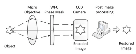
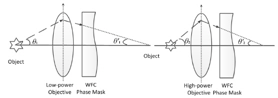
A schematic of a wavefront coding microscopy imaging system is shown in Fig. 1.
A WFC phase mask is located at the system pupil plane after the micro-objective. CCD detects an encoded image with the same blur degree at different defocus distances due to the modulation of the phase mask. Then, a sharp image will be restored by the same de-convolution filter, which is built through the system PSF.
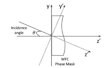
Numerical aperture (NA) of a micro-objective is closely related to the maximum incidence angle of light in object space, which determines its resolution. That means micro-objectives with different powers are not the same. When introducing a WFC phase mask in a microscopy system, the incidence angle of light at the phase mask also changes following the converting of micro-objectives. It is shown in Fig. 2. In order to extend the depth of field of micro-objectives with different powers using one phase mask, the influence of different incidence angle of light at the phase mask is analyzed as follows.
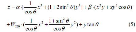
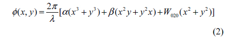
We select a mixing symmetrical CPM due to its manufacturing convenience. Its surface shape is represented by

Where
For an aberration-free optical system with only defocus, its pupil function modulated by CPM is represented by
Where,

The difference of incidence angle at CPM could be regarded as a rotation of coordinates, shown in Fig. 3, and transformation formulas between two coordinates can be represented by
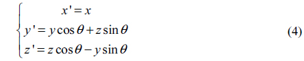
Where,
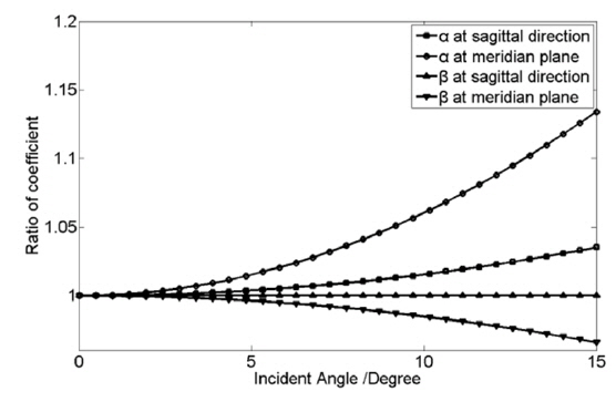
Substituting Eq. (4) into Eq. (1) and simplifying, the pupil function with different incidence angles is represented by

The coefficients of CPM in pupil function vary with the incidence angle. It is shown in Fig. 4. Coefficient
III. THE OPTIMIZATION OF WAVEFRONT CODING PHASE MASK OF MICRO-OBJECTIVES WITH DIFFERENT POWERS
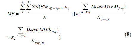
Based on the invariance of PSF, the merit function (MF) for WFC phase mask is represented by
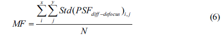
Where,
Variation of coefficients of phase mask will introduce more aberration in the microscopy imaging system, which results in decrease of value of MTF near spatial cut-off frequency. That creates a decline of resolution of the optical system.
Thus, optimization of our CPM adds a punishment function (PF) in order to eliminate or decrease this impact, and taking the difference between meridian and sagittal directions into consideration. The PF is represented by
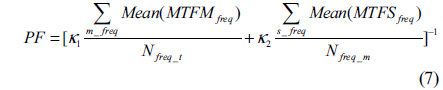
Where,
Then, the merit function for CPM is represented by
Finally, through an optimization search algorithm, such as a genetic algorithm (GA) or simulated annealing algorithm (SA), we could solve for the optimal coefficients of the CPM.
IV. OPTIMIZATION RESULT AND DISCUSSION
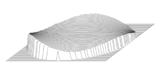
Shape of optimized CPM is shown in Fig. 5.
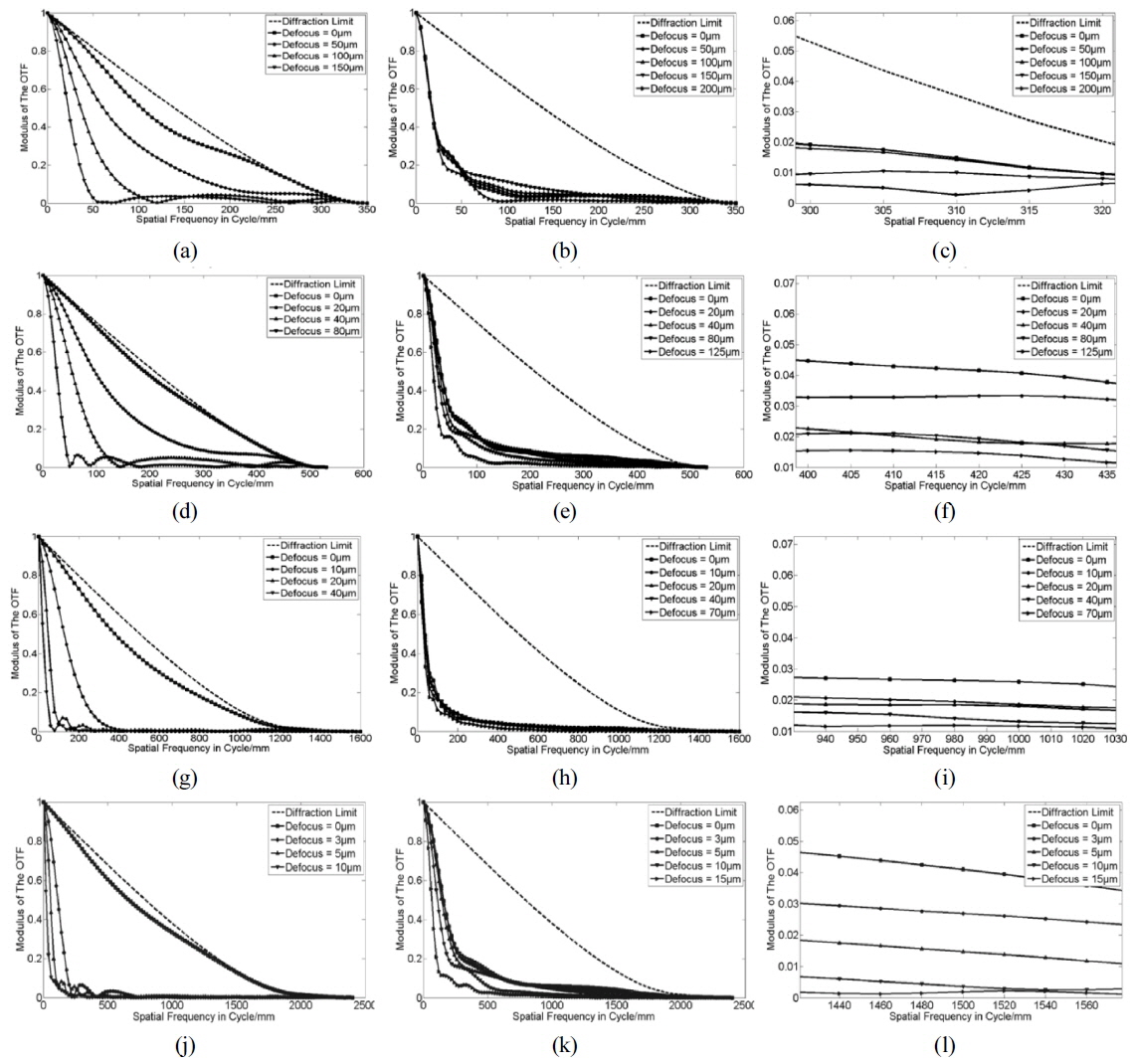
We combine this phase mask with 5X, 10X, 20X and 40X micro-objectives, computing their MTF in optical design software (ZEMAX). These results are shown in Fig. 6. The MTFs of all micro-objectives with the phase mask have an acceptable value near the cut-off frequency, by which we mean not losing any high spatial frequency, maintaining the resolution of microscopy. In addition, the higher power the micro-objective is, the larger is the extension of the ranges of depth of field with the optimized CPM. For 5X objective, its depth of field is extended from 75 µm (without CPM) to about 200 µm (with CPM). It can be seen from Fig. 6(c), the value of MTF for the optical system with CPM at defocus distance 200 μm is already very small. That demonstrates the maximal ability of the CPM for extending the depth of field, because the value of MTF will drop to zero probably when defocus distance is over 200 μm for a practical optical system with aberrations. Similarly, the optimized CPM multiplies the depth of field of 10X, 20X, 40X objectives five to ten times.
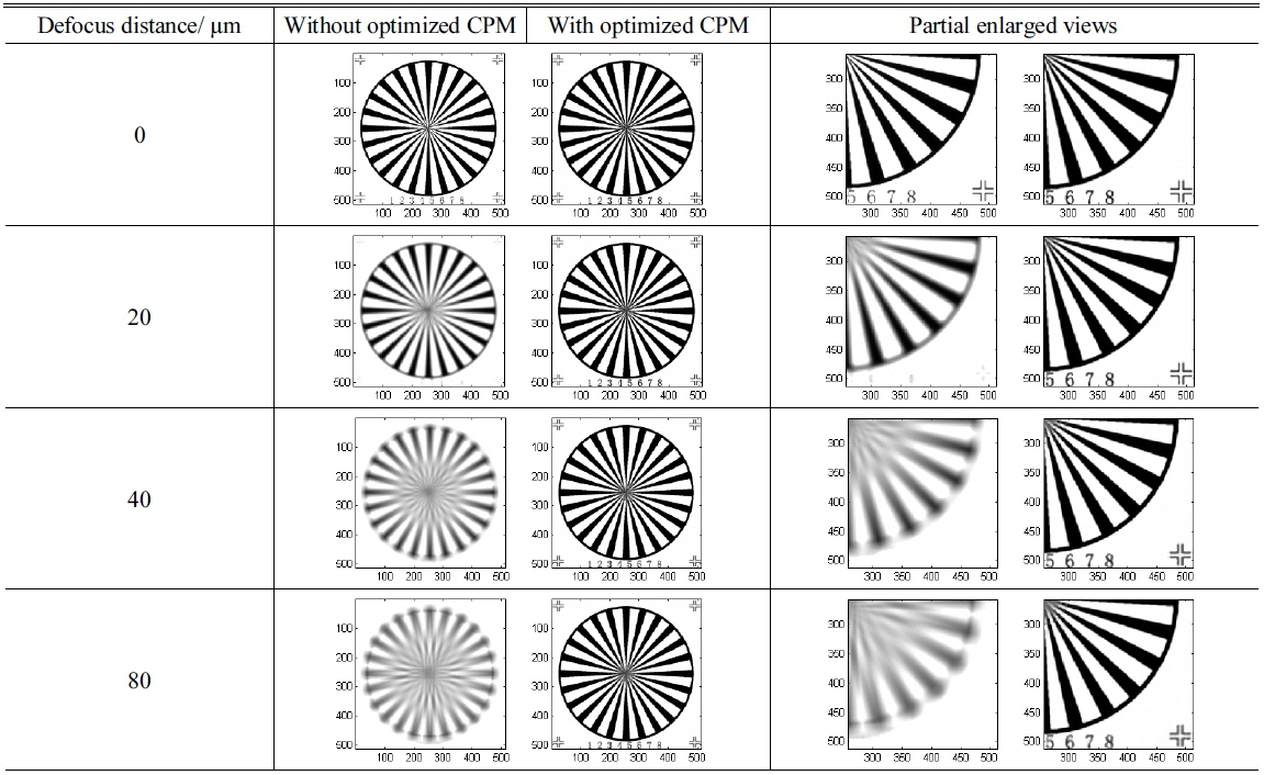
Since the micro-objectives with optimized CPM maintain their proper spatial cut-off frequency, the shape images can be restored from the encoded images. Below we present the comparison of microscopy imaging simulation results of micro-objectives with different powers at different defocus locations. These results are exhibited in Tables 1-4. The target image is a spoke pattern with numbers and marks at corners of which the size is 512 × 512 pixels. The coordinates in all figures in Tables are in pixels.
[TABLE 1.] Imaging simulation results of 5X micro-objectives
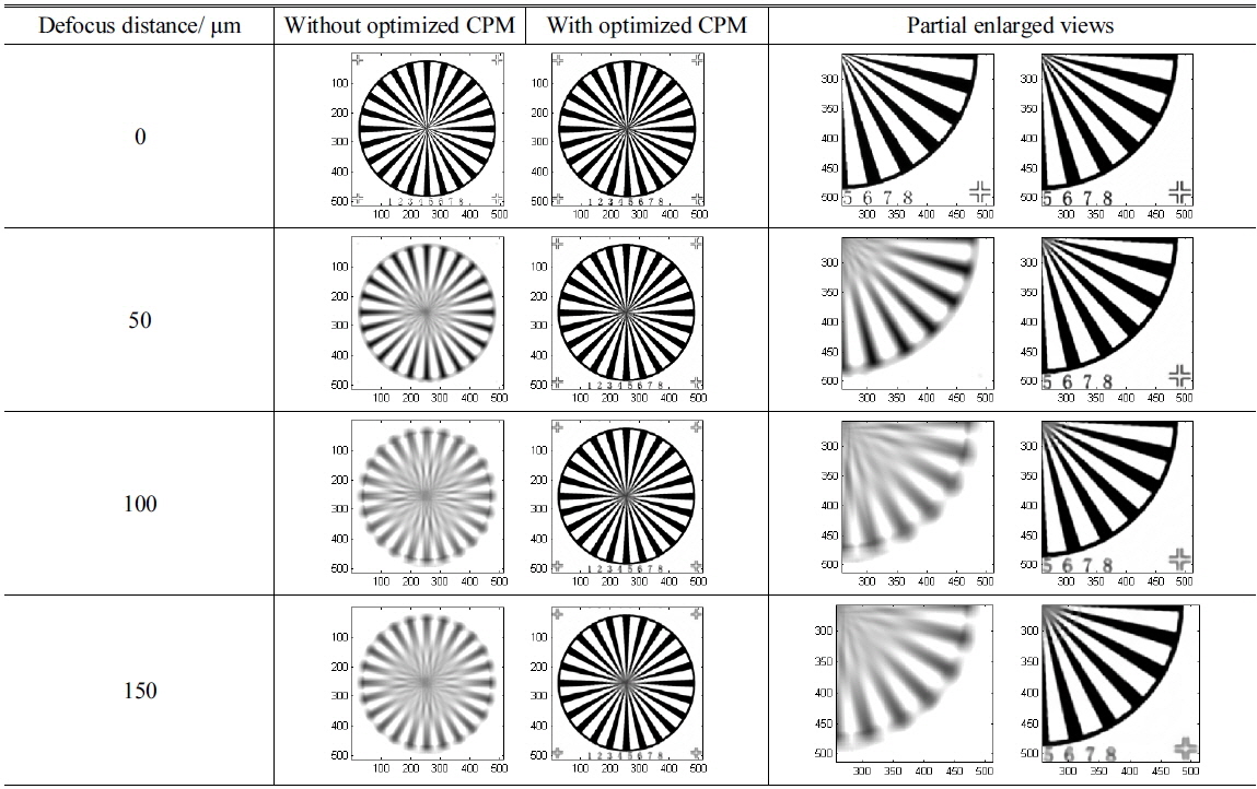
Imaging simulation results of 5X micro-objectives
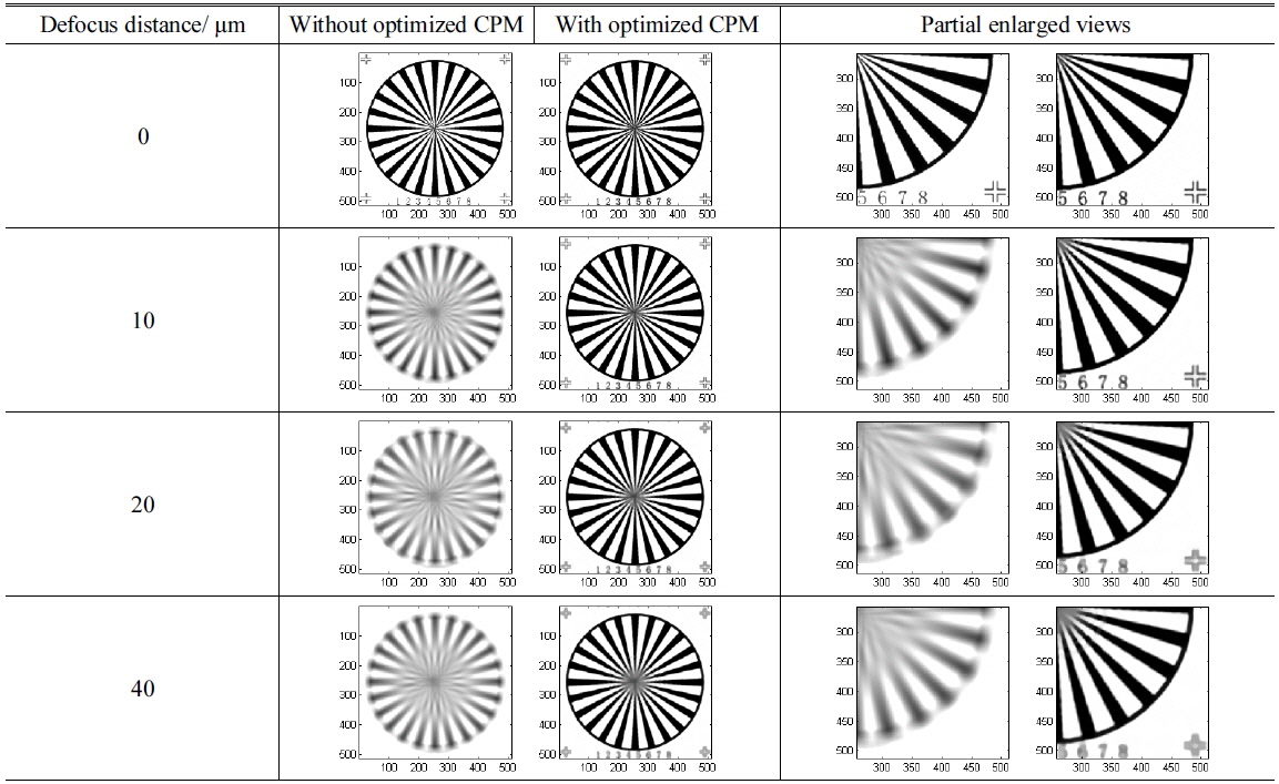
[TABLE 2.] Imaging simulation results of 10X micro-objectives

Imaging simulation results of 10X micro-objectives
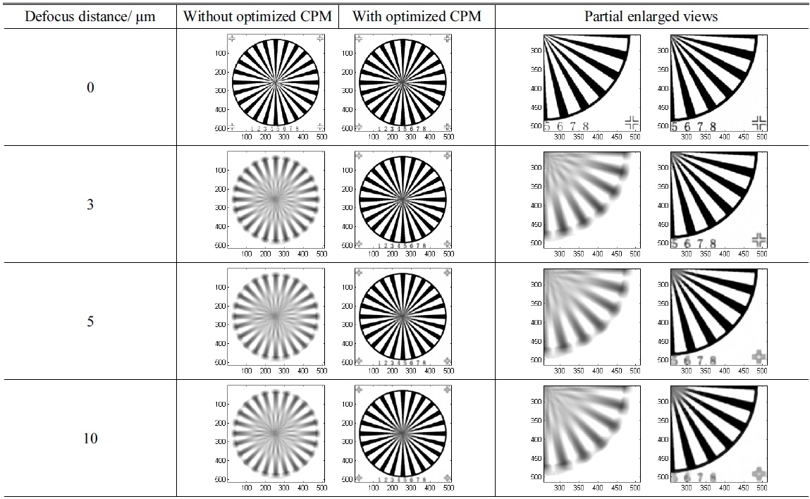
[TABLE 3.] Imaging simulation results of 20X micro-objectives
Imaging simulation results of 20X micro-objectives
[TABLE 4.] Imaging simulation results of 40X micro-objectives
Imaging simulation results of 40X micro-objectives
Based on the theoretical analysis of the relationship between the incidence angle of light and pupil function, a mixing symmetrical cubic wavefront phase mask has been optimized. The depth of field of 5X-40X micro-objectives optical system have multiplied 3 to 10 times larger after introducing optimized CPM. In addition, the results of microscopy imaging simulation with different defocus distance show its ability in enhancement for defocus imaging.