Liquid crystal (LC) materials have an effective refractive index which can be easily varied using thermal, electric, and magnetic fields. Therefore, optical-fiber sensors based on LC devices [1-3] have attracted attention in the electric power industry as devices to measure the electro-magnetic field. There are several optical-fiber sensors using the LC devices, such as an LC infiltrated photonic crystal fiber, an LC tunable fiber polarizer, an LC film, and a Fabry-Perot (FP) etalon with an LC [4-8]. In particular, an FP etalon with an LC [7, 8] has advantages such as simple structure, high finesse, and low-voltage drive. The LC in the FP etalon is used as an active medium that can be controlled by changing the applied voltage. Therefore, it can be used as a wavelength-tunable filter. Several nematic LC (NLC) FP tunable filters have been reported in various configurations [8-10]. When the NLC in the FP etalon is homogeneously aligned between alignment layers, the alignment of the NLC directors is gradually reoriented according to the applied electric-field intensity [3]. It is very important to measure the effective refractive index of the LC for use as a sensing device. In this study, we measure the effective refractive index of the NLC inside the FP etalon according to the applied electric fields by using the wide-band wavelength-swept laser (WSL) with a polygon-scanner-based wavelength filter. We fabricate three types of NLC FP etalons having thicknesses of 30.6 μm, 55.4 μm, and 108.8 μm. For each case, the Freedericksz transition voltages are measured. The effective refractive index of the NLC depends on the applied static-electric-field intensity.
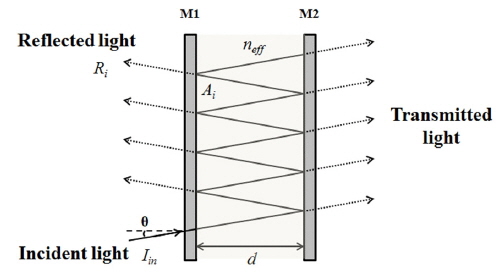
The FP etalon is the most commonly used device for producing a large number of mutually coherent beams by dividing the amplitude. Figure 1 shows a schematic of a simple case of the FP etalon. Even though the mirrors are flat and parallel, there are losses due to scattering or absorption in the mirror. In this study, we will consider only normal incidence to the FP etalon. Inside the FP etalon, which consists of two parallel and partially reflecting surfaces, the incident beam is innumerably reflected and multiple transmitted beams interfere.
The optical path difference between any two successive transmitted rays is 2
where
here
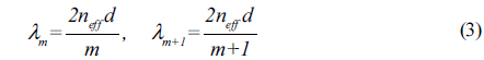
The effective refractive index is calculated from Eq. (3) as follows:
The effective refractive index can be estimated by measuring two consecutive wavelengths.
III. NEMATIC LIQUID CRYSTAL FABRY-PEROT ETALON
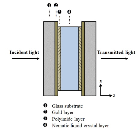
The commercially available 4-cyano-4’-pentylbiphenyl (5CB, from Merck) is used as the NLC. This compound exhibits nematic-phase properties in the temperature range of 24℃ to 36℃. In order to measure the effective refractive index of the NLC, an FP etalon with NLC is fabricated. The cell structure of the fabricated NLC FP etalon is shown in Fig. 2. It consists of glass substrates, gold layers, polyimide layers, and an NLC layer. The gold layers, having highly reflective surfaces, are deposited on the glass substrates and are used as the electrodes. The gold layers cause high optical loss owing to their high reflectance and absorption. To reduce this optical loss, they can be fabricated with dielectric materials and indium tin oxide [11]. The polyimide layers function as planar alignment layers and are deposited on the gold layers and rubbed for the alignment of NLC molecules along the surfaces.
The NLC is homogeneously aligned between the polyimide layers. The thickness of the gold layer is approximately 30 nm. The NLC is aligned parallel to the polyimide layers (
The polarization of the input beam can be controlled in the direction of the extraordinary mode. Then, there only exists the extraordinary mode of the transmitted peaks from the NLC FP etalon [3]. In the experiments, we fabricated three types of FP etalons having thicknesses of 30.6 μm, 55.4 μm, and 108.8μm. The reflectivity of the gold layer and insertion loss of the NLC FP etalon are ~ 90% and ~ 20 dB, respectively.
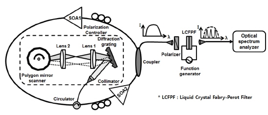
Figure 3 shows the experimental setup for measurement of the effective refractive index variation of the NLC with respect to the applied electric field. The setup consists of a WSL, an NLC FP etalon, and a linear polarizer. The wideband, high-power WSL incorporating a polygon-scanner-based wavelength filter is used as a broadband optical source. It comprises two semiconductor optical amplifiers (SOAs), two polarization controllers, an optical circulator, an optical output coupler, and a polygon-scanner-based wavelength filter. The bandwidth of the WSL is greater than that of the ASE from the SOA. The dotted box in the figure represents the polygon-scanner-based wavelength filter, which consists of a polygon rotating mirror, a diffraction grating, and two achromatic doublet lenses [12].
Since the NLC FP etalon has high insertion loss, two SOAs are used to improve the output power of the WSL [13]. The center wavelength of the WSL is approximately 1310 nm, and the output power is greater than 20 mW. The 3 dB bandwidth of the WSL is greater than 90 nm. The collimated output beam of the WSL is launched into the NLC FP etalon through a linear polarizer. External electric fields are applied to the NLC FP etalon by using an arbitrary function generator (Tabor Electronics Inc., 8023). The applied voltage has a square waveform with 10-kHz AC voltage to protect the material from electrolytic disruption [14]. The output of the NLC FP etalon is collected using a collimator and measured with an optical spectrum analyzer while the applied voltage is gradually increased from 0 to 9 V. In the experiments, the applied voltages are converted to the applied electric fields according to the thickness of the NLC cell because it is more appropriate to discuss the results in terms of voltages per unit thickness.
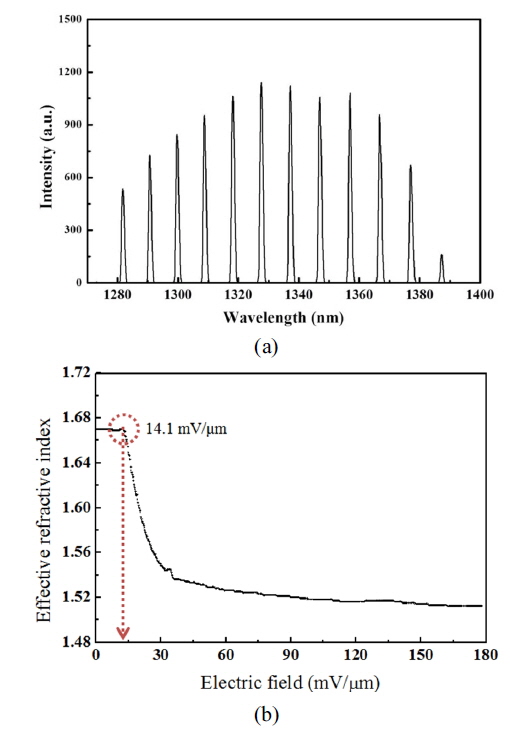
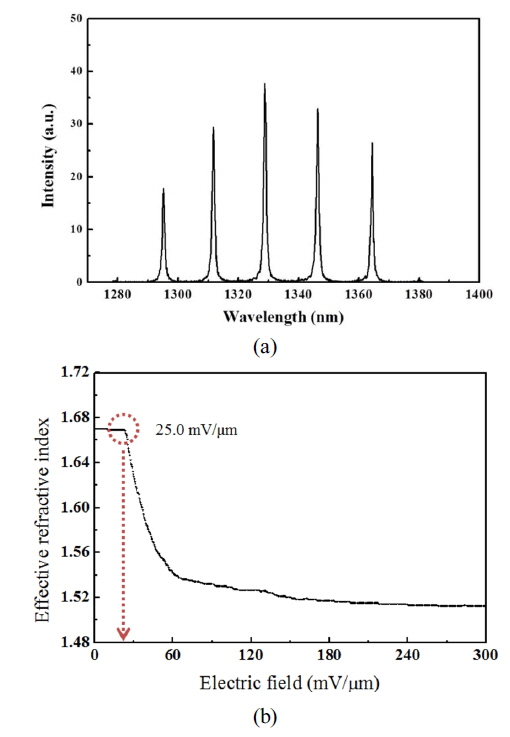
Figure 4 (a) shows the optical spectrum of the transmitted output from the NLC FP etalon of thickness 30.6 μm. The effective refractive index can be estimated by selecting two arbitrary consecutive wavelengths of the transmitted peaks. Figure 4 (b) shows a plot of the effective refractive index of the NLC as a function of the static applied electric field for the 30.6-μm-thick etalon. Under the threshold voltage corresponding to the Freedericksz transition voltage [15], the effective refractive index does not change with the applied electric field. Above the threshold voltage, however, the LC directors rotate because of the force balanced between the elastic restoring force and the torque of the induced dipole moment caused by the external electric field as the applied electric field increases. The Freedericksz transition voltage was approximately 0.77 Vrms for the 30.6-μm-thick NLC FP etalon. The threshold value of the electric field corresponding to the Freedericksz transition was approximately 25.0 mV/μm. For electric fields greater than ~150 mV/μm, the effective refractive index gradually saturated.
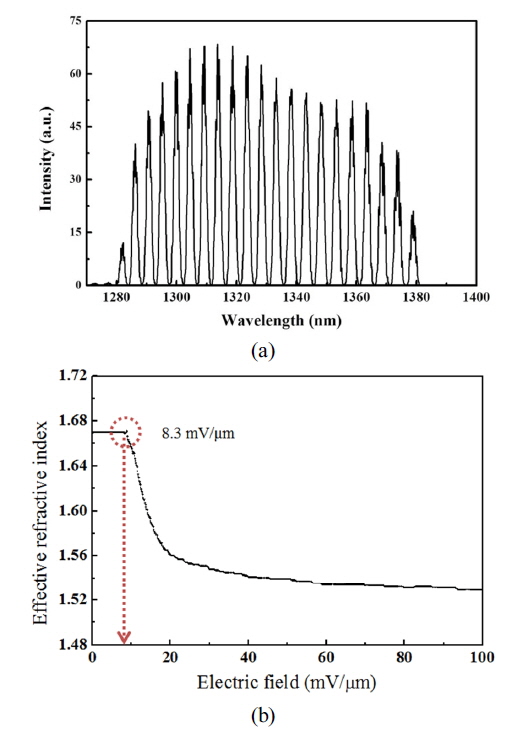
Figure 5 (a) and 6 (a) show the optical spectra of the transmitted output from the NLC FP etalons of thicknesses 55.4 μm and 108.8 μm, respectively. The peaks in Fig. 6 (a) are broader than those in Figs. 4 (a) and 5 (a) because of the misalignment of the NLC FP etalon. The interval between two arbitrary consecutive wavelengths decreases as the thickness of the NLC FP etalon increases. Figure 5 (b) and 6 (b) show plots of the effective refractive index of NLC as a function of the static applied electric field for 55.4-μm-thick and 108.8-μm-thick NLC FP etalons, respectively. The Freedericksz transition voltages for the 55.4-μm-thick and 108.8-μm-thick NLC FP etalons were approximately 0.78 Vrms and 0.90 Vrms, respectively; the threshold values of the electric fields corresponding to these Freedericksz transition voltages were approximately 14.1 mV/μm and 8.3 mV/μm, respectively. The effective refractive indices at electric fields greater than 100 mV/μm and 50 mV/μm gradually saturated for 55.4-μm-thick and 108.8-μm-thick etalons, respectively, as shown in Fig. 5 (b) and Fig. 6 (b). The effective refractive indices of the NLC for the three fabricated NLC FP etalons remain at approximately 1.67 until the threshold electric fields are reached. On the other hand, beyond the threshold electric field, the effective refractive indices quickly decrease and eventually saturate at a value of 1.51 for all cases. The measured Freedericksz transition voltages were nearly equal for the 30.6-μm-thick and 55.4-μm-thick NLC FP etalons. However, the measured Freedericksz transition voltage of the 108.8-μm-thick etalon was slightly higher than those of 30.6-μm-thick and 55.4-μm-thick etalons. The reason is that the directors require more time to stabilize inside the FP etalon for the 108.8-μm-thick NLC FP etalon.
We successfully measured the effective refractive index of a nematic liquid crystal (NLC) in a Fabry-Perot (FP) etalon according to the applied electric field by selecting two arbitrary consecutive wavelengths of the transmitted peaks. A wide-band, high-power, wavelength-swept laser is used as an optical source to measure the transmitted peaks of the NLC FP etalons. We measured the Freedericksz transition voltages for three types of the NLC FP etalons having thicknesses of 30.6 μm, 55.4 μm, and 108.8 μm. The Freedericksz transition voltages were nearly equal in all three cases. However, the threshold value of the electric field corresponding to the Freedericksz transition voltages decreased as the thickness of the NLC FP etalons was increased. The measured effective refractive indices in the three cases decreased from 1.67 to 1.51 as the applied electric field was increased.