검색 전체 메뉴
PDF
맨 위로
OA 학술지
Terabit-Per-Second Optical Super-Channel Receiver Models for Partial Demultiplexing of an OFDM Spectrum
  • 비영리 CC BY-NC
  • 비영리 CC BY-NC
ABSTRACT
Terabit-Per-Second Optical Super-Channel Receiver Models for Partial Demultiplexing of an OFDM Spectrum
KEYWORD
Orthogonal frequency division multiplexing (OFDM) , Super-channel , Partial demultiplexing , Coherent modulation , Fast Fourier transform (FFT) processor
  • I. INTRODUCTION

    To meet the forecasted growth rate of internet traffic, on the order of Tb/s, enhancing the capacity of a singlecarrier transmission system is critically challenging, due to the large penalty from fiber impairments and also a lack of high-speed commercial electronics, which are most likely to remain unavailable in the foreseeable future. Even though the capacity of a transmission system can be increased by incorporating higher-order modulations, such as PM-16QAM or PM-64QAM [1], it becomes more susceptible to noise, and its reach also decreases as the modulation order increases. In this regard, optical super-channel technology can be viewed as a strong candidate to satisfy tangible Tb/s transmission, where coherently generated, dense multiple carriers are demultiplexed and decoded by orthogonal frequency multiplexing (OFDM) [2], or by Nyquist wavelength division multiplexing [3]. In a super-channel transmission system, the required capacity is usually attained by combining a large number of optical carriers, where each carrier maintains a certain phase relation to the others and is modulated at a lower bit rate, so as to be terminated at a receiver for a service interface [4]. The first successful long-haul super-channel transmission of 1.15 Tb/s over a distance of 10,000 km was reported in [5], while a record-breaking 26 Tb/s super-channel transmission experiment was reported in [2]. In this paper, the super-channel is formed using OFDM technology because of its potentially high spectral efficiency, fine-granularity, and high tolerance of transmission impairments like optical nonlinearity [6], chromatic dispersion [7], and polarization mode dispersion [8].

    One of the crucial requirements for successfully deploying optical super-channel technology is the flexibility in carrier assignments, where an arbitrary number of multiple adjacent carriers are grouped to form subbands that can be demultiplexed and demodulated independently from other subbands. This enables the super-channel to provide flexible services of various requirements elastically, to handle differing capacity, modulation format, spectral efficiency, number of carriers, bandwidth, etc., for each subband. A typical super-channel receiver can demultiplex and demodulate a small number of carriers in a group (i.e. a subband) out of a large number of super-channel carriers by using electronic numerical OFDM and Nyquist filtering after optical heterodyning coherent detection, or by means of all-optical OFDM. A key technique to demultiplex the OFDM carriers is the DFT, which can be realized either electronically or purely optically [9]. These two DFT approaches can form two distinct OFDM super-channel receiver models as partial carrier demultiplexers for subband demultiplexing. A major burden on the electronic DFT-based partial carrier demultiplexer is the power-hungry ADC. If the DFT can be performed on a continuous signal using an optical DFT circuit, then the power and bandwidth consumptions of the system can be reduced significantly. In this paper, we investigate these two options for Tb/s optical super-channel OFDM receivers that can terminate a subband.

    II. PRINCIPLE OF PARTIAL DEMULTIPLEXING IN AN OFDM SUPER-CHANNEL TRANSMISSION SYSTEM

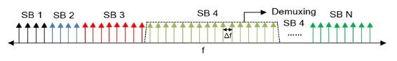
    In an OFDM super-channel environment, the spectrum can be extremely wide, since hundreds of OFDM carriers are multiplexed over a single wavelength. In this work, we focus on how to demultiplex a portion of the entire OFDM spectrum. For a better understanding, we intuitively divide the entire spectrum into multiple OFDM subbands and decode each subband with partial demultiplexing, as shown in Fig. 1. There are no restrictions on the number of subbands in the spectrum, nor on the number of carriers in each subband. Due to the orthogonality property of the OFDM [10], the carriers in each subband can have a spacing of Δf, corresponding to the reciprocal of the symbol rate. There is no guard band between subbands; in other words, the subbands are orthogonal to each other.

    In this paper, by considering all-optical and electronic DFT technologies, we investigate two OFDM super-channel receiver models for partial carrier demultiplexing with minimum power and bandwidth consumptions.

    III. SUPER-CHANNEL SYSTEM MODEL

    In this section, we discuss our system model for the Tb/s optical OFDM super-channel transmission system, which includes transmitter and receiver designs. We first describe the transmitter setup, and then the receiver setup for partial carrier demultiplexing.

       3.1. OFDM Super-channel Transmitter Model

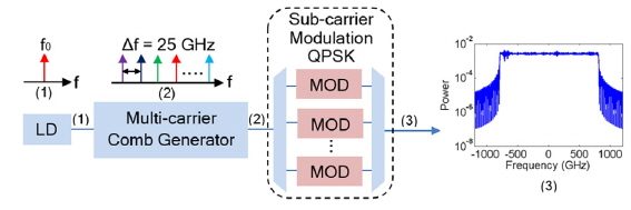
    In the transmitter, a set of frequency-locked carriers is assumed to be generated from a mode-locked laser (MLL) synchronized at its fundamental frequency [11], a comb generator employing a concatenated, overdriven optical phase modulator [2], or a recirculating frequency shifter, as shown in Fig. 2. Similar to a DWDM approach, we deploy an arrayed waveguide grating (AWG) device to split the frequency comb into its nonoverlapping Fourier components with a channel spacing of Δf = 1/T. Subsequently, the frequencylocked carriers are individually modulated and combined together to form a Tb/s optical OFDM super-channel. This transmitter design offers several definitive advantages over the conventional approach: (1) no electronic IFFT (inverse fast Fourier transformation) block is required; (2) no data-rate limitations are imposed by electronics, including the digital-to-analog converter (DAC); and (3) the carriers can be modulated individually.

    In this work, a total number N = 64 carriers with an exact frequency spacing of Δf = 25 GHz is modeled to realize an OFDM super-channel transmission system, in which each carrier is individually modulated using coherent modulation, according to a pseudorandom binary sequence (PRBS) with a length of 215-1. The modulated signals are then combined to form a 3.2 Tb/s OFDM super-channel.

       3.2. OFDM Super-channel Receiver Model

    In this subsection, we present two optical super-channel receiver models as partial carrier demultiplxers. These can be termed as (1) an electronic FFT-based CO-OFDM, and (2) an all-optical demultiplexing and coherent demodulation OFDM super-channel receiver.

    3.2.1. Electronic FFT-based CO-OFDM Super-channel Receiver

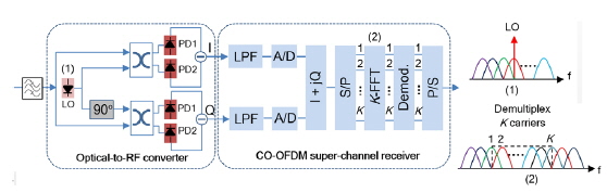
    A schematic diagram of the coherent optical-OFDM (CO-OFDM) super-channel receiver is illustrated in Fig. 3. In this design, the FFT is performed electronically. The major components of the receiver include: (1) a homodyne coherent receiver; (2) two ADCs; (3) an electronic FFT circuit; and (4) a phase estimator, to eliminate the phase noise generated from an LO. Although the architecture of the homodyne receiver is quite complex, it is a preferred technology, because of its minimal electrical-bandwidth requirement and 3-dB higher sensitivity, compared to heterodyne detection [12].

    In the first place, the transmitted coherent modulated optical signals are extracted, using a second-order super-Gaussian filter with a bandwidth marginally larger than K × Δf GHz, where K denotes the number of carriers. Then the extracted time-domain optical OFDM signals are fed to a coherent receiver, where each component of the signals is coupled with an LO in a 90° optical hybrid, followed by an antialiasing low-pass filter, before being detected by the two photo-detectors to obtain in-phase (I) and quadrature (Q) components of the signals. In this work, to limit the bandwidth consumption of the system, the LO is tuned at the center frequency of the subband to be demultiplexed. The I/Q components of the signals are sent to an ADC to obtain time-domain sampling (TDS). The digitized I/Q components of the signals are then combined prior to serial-to-parallel conversion. With a higher sampling rate, the cost and power consumption of the ADCs increase rapidly, so it is important to limit the sampling rate of an ADC. Subsequently, the time-domain samples are fed to an electronic FFT circuit to demultiplex k carriers in a subband. Finally, each carrier is equalized using the Viterbi-and-Viterbi method [13], to compensate for the phase and amplitude distortions caused by the optical and electrical paths.

    3.2.2. All-optical Demultiplexing and Coherent Demodulation OFDM Super-channel Receiver

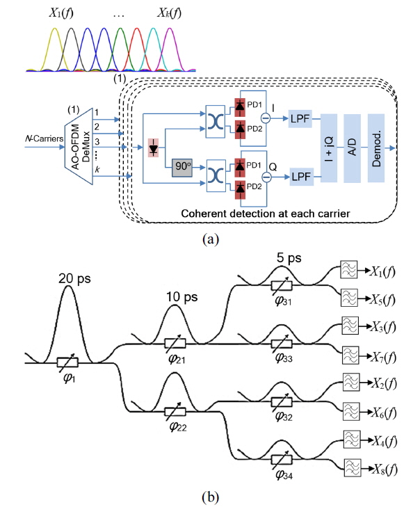
    The AO-DFT-based all-optical demultiplexing and coherent demodulation OFDM super-channel receiver is illustrated in Fig. 4(a). The major components of the receiver are (1) an AO-DFT circuit for partial carrier demultiplexing, and (2) a coherent receiver for optical-to-electrical (O/E) conversion and symbol demodulation in each demultiplexed carrier. Therefore, we first introduce the AO-DFT process, and then the overall operation of the receiver is discussed.

    The AO-DFT circuit is a simple device that can perform both serial-to-parallel conversion and DFT processing all-optically. In this paper, the DFT is realized by tuning the phase of Mach-Zehnder delay-and-add interferometers (MZDI), couplers, and optical gates. With this device the DFT can be performed on a continuous signal, so no ADCs are required. In addition, the circuit consumes little or no power, as it consists of passive optical components. An exemplary illustration of an 8-point AO-DFT circuit can be found in Fig. 4(b). For an 8-point AO-DFT, we cascade 3 MZDIs for each carrier, with delay and phase adjustments in the upper and lower arms respectively. At the end of the AO-DFT circuit, an optical gate, such as an electro-absorption modulator (EAM), is placed at each output arm of the last cascading stage, to sample at the center of a symbol period. The transfer function of cascaded couplers with a delay line in the lower arm of a MZDI is expressed in Eq. (1) [11].
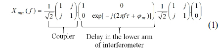
    image

    In Eq. (1), τ and ϕ m denote the delay and phase shift in the lower arm of the interferometer, respectively, which are defined as τ = T / 2n and ϕnm = 2π (m / N) - π . Here, n represents the stages of an N-point DFT, and m < N/2.

    In this receiver design, the transmitted signals modulated by QPSK are demultiplexed first using a MZDI-based k-point AO-DFT circuit, as discussed above. The received signals at each of the k demultiplexed carriers are coupled with a reference LO in a 90° optical hybrid, followed by balanced photodetectors for optical-to-electrical (O/E) conversion. Finally the symbols received at each carrier are equalized using the Viterbi-and-Viterbi [13] method, to mitigate the amplitude and phase distortions.

    IV. RESULTS

    In this section, we investigate the performance of the super-channel receivers in elastic demultiplexing at a transmission rate of 64 × 50 Gb/s over an amplified fiber, with an amplified spontaneous emission (ASE) noise model. The simulated transmitter model follows the design presented in Section 3.1. Because of the carrier spacing of 25 GHz, the symbol duration is assumed to be T = 40 ps for orthogonality. A total number of N = 64 OFDM carriers centered on 193.1 THz are coupled to form a 3.2 Tb/s OFDM super-channel. The generated OFDM signals are transmitted over a dispersion-compensated fiber; therefore, no OFDM overhead, such as a cyclic prefix, is required. For balanced coherent detection we use an LO laser, which is assumed to be noiseless and therefore works as a noiseless optical amplifier. In the simulation, the major performance parameter is bit-error rate, which is measured by comparing the received bit sequence to the transmitted bits and counting the number of errors, with respect to the optical signal-to-noise ratio (OSNR). Typically the OSNR is defined as the ratio of the transmitted optical signal power to the ASE noise power with a reference bandwidth of 0.1 nm (approximately 12.5 GHz for 1550-nm transmission). The total number of transmitted OFDM symbols in a single run is 512. Every BER point in the plots is obtained by iteratively running the simulation many times.

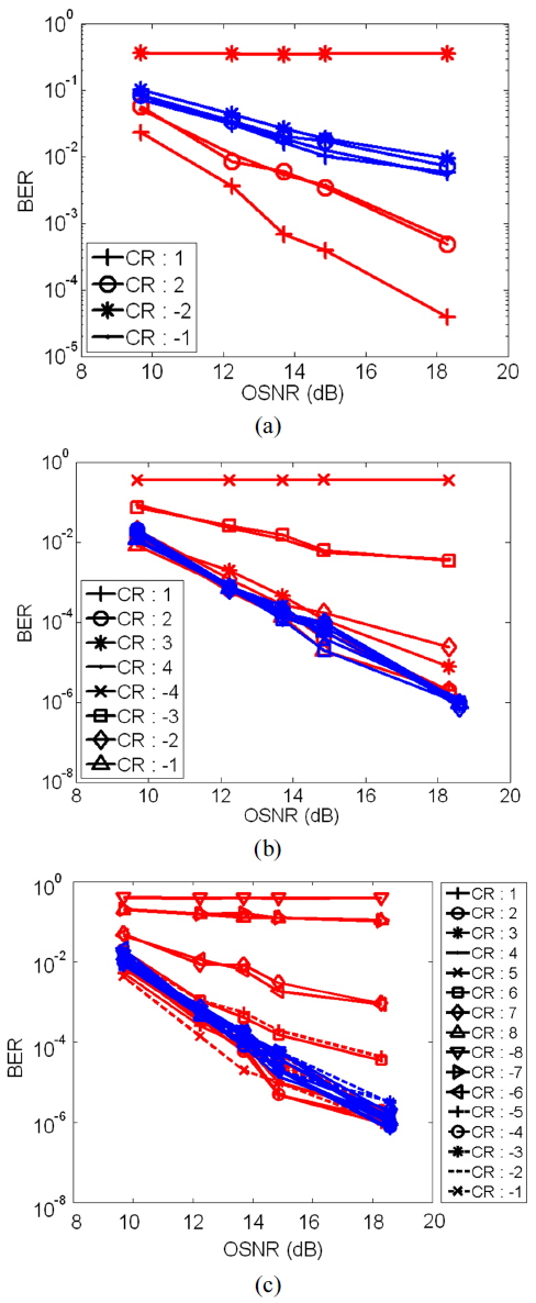
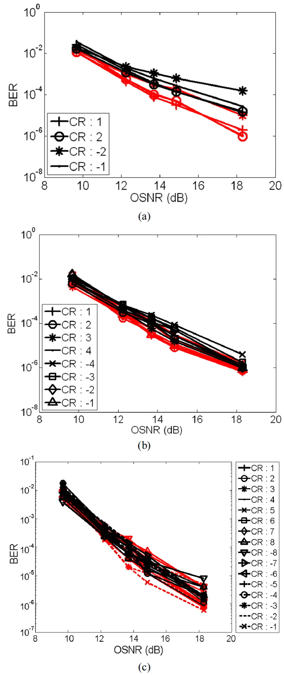
    Figure 5 compares the BER performances of the aforementioned receiver designs as a function of OSNR for a back-to-back transmission situation. The data in the figure correspond to the BER results in demultiplexing of subbands with k = 4, 8, and 16 carriers as 100, 200 and 400 GHz widths, respectively. In the case of the electronic FFT-based CO-OFDM super-channel, after balanced detection the signal passes through an antialiasing low-pass filter. Now we collect k = 4, 8, and 16 equidistant samples (no oversampling) at sampling frequencies of fs = 100, 200, and 400 GS/s respectively in a symbol period of Ts = 40 ps, and then performed k-point FFT to demultiplex the k carriers. Note that the red and blue curves show respectively the BER results of the electronic FFT-based CO-OFDM and AO-DFT-based coherent modulated OFDM super-channel receivers. In Fig. 5, the carriers are labeled as –NSB / 2, - (NSB / 2-1), ⋯ -2, -1, 1, 2, ⋯, (NSB / 2-1), NSB / 2, where NSB denotes the number of carriers in a subband and ± NSB / 2 corresponds to the edge-most carriers in a subband.

    Figure 5(a) shows BER versus OSNR data for NSB = k = 4 demultiplexing carriers of a 100 GHz subband. For the electronic FFT-based CO-OFDM receiver, the BER of the center carrier of the subband (CR: 1) is ~10-5 at 18.6 dB. We notice that the edge-most carriers (CR: -2) completely failed in decoding, due to aliasing effects between carriers located at +50 GHz and –50 GHz. We also experience a noticeable performance degradation of the carriers close to the edge of the decoded subband. In the case of an AO-DFT-based receiver, a 4-point DFT is achieved by cascading two MZDIs followed by optical gates to demultiplex k = 4 carriers, as depicted in Fig. 4(b). Despite an equal gain in performance at every carrier, we observe that the performance of any carrier is not satisfactory under any OSNR values.

    Figures 5(b) and 5(c) present similar data plots for NSB = k = 8 and NSB = k = 16 demultiplexing carriers as 200 GHz and 400 GHz subbands, respectively. For the electronic FFT-based CO-OFDM receiver, the measured BER is around 10-6 at 18.6 dB for the carriers located around the center of the demultiplexed subband. As seen in Fig. 5(a), we notice a significant degradation in BER performance of the edge-carriers. For the AO-DFT-based coherent demodulation OFDM super-channel receiver, we cascade three and four MZDIs to demultiplex NSB = 8 and NSB = 16 carriers, respectively. The performances of all carriers are almost equal (around 10-6 at 18.6 dB) for both NSB = 8, and NSB = 16 cases. Aliasing is not observed in any case.

    One possible way to mitigate the effect of aliasing on the electronic FFT-based CO-OFDM super-channel receiver is oversampling. In this paper, two oversampling scenarios are considered: Case 1, 50% oversampling, and Case 2, 100% oversampling. In Case 1, 50% oversampling is achieved by sampling a signal with k = 3NSB/2 equidistant samples in a symbol period of T. In Case 2, the number of equidistant samples in a symbol period is increased to k = 2NSB. However, the number of demultiplexed carriers remains NSB for the both cases. Figure 6 shows BER versus OSNR performance for NSB = 4, 8, and 16 demultiplexed carriers. In this figure the black and red curves respectively show the performance with 50% and 100% oversampling. From Fig. 6(a) we can see that the performance with 50% oversampling is overshadowed by the performance with 100% oversampling, in the case of NSB = 4 demultiplexing carriers. It is important to note that the impact of aliasing is nearly removed. Similarly, a marginal discrepancy in BER performance is observed in comparing the two oversampling cases in Figs. 6(b) and 6(c). Although oversampling can improve the performance of the receiver in subband decoding, it accordingly increases the power consumption of the system. To limit power consumption, 50% oversampling can be a seen as a good choice for reasonable performance.

    Several important conclusions can be drawn from the above simulation results: (1) With AO-DFT, all carriers can realize nearly equal gain in performance and no carriers suffer from aliasing, because the optical waveform of the symbol is demultiplexed before being sampled. (2) A 4-point MZDI-based AO-DFT circuit failed in demultiplexing, and at least three cascaded 8-point MZDIs or NSB ≥ 8 are required to obtain reasonable performance. (3) The performance of an electronic FFT-based CO-OFDM receiver improves with oversampling, i.e. k > NSB, at the price of increased consumption of power and bandwidth. (4) The AO-DFT process has several advantages over the electrical FFT. It consists of passive optical components and hence consumes little or no power. Unlike for electronics, there is no data-rate limitation, and also it offers simpler implementation. Therefore, the AO-DFT circuit can be directly adapted to any flexible modulation rate.

    V. CONCLUSION

    In this paper, we model a 64 × 50 Gb/s optical OFDM super-channel transmission system with 64 carriers, and demultiplex the super-channel carriers flexibly in the form of a subband, using two distinct receiver designs. The receivers for partial-carrier demultiplexing employ electronic and all-optical DFT technologies respectively to form (i) an electronic FFT-based super-channel receiver, and (ii) an AO-DFT-based super-channel receiver. The BER-performance results reveal that the electronic FFT-based super-channel receiver suffers from aliasing, which can be mitigated by oversampling. The simulation results also reveal some minor limitations of MZDI-based AO-DFT implementation that require more than the first few MZDI cascading stages. Nonetheless, the AO-DFT-based super-channel receiver consumes no or little power. It neither suffers from aliasing nor requires any ADC/DAC. Therefore the significance of an AO-DFT-based partial carrier demultiplexer in optical super-channel technology could be immense.

참고문헌
  • 1. Asif R., Islam M. K., Zafrullah M. 2013 “All-optical signal processing of fiber impairments in dual-polarization 112 Gbit/s m-ary QAM coherent transmission,” [J. Opt. Soc. Korea] Vol.17 P.57-62 google cross ref
  • 2. Hillerkuss D., Schmogrow R., Schellinger T., Jordan M., Winter M., Huber G., Vallaitis T., Bonk R., Kleinow P., Frey F., Roeger M., Koenig S., Ludwig A., Marculescu A., Li J., Hoh M., Dreschmann M., Meyer J., Ezra S. B., Narkiss N., Nebendahl B., Parmigiani F., Petropoulos P., Resan B., Oehler A., Weingarten K., Ellermeyer T., Lutz J., Moeller M., Huebner M., Becker J., Koos C., Freude W., Leuthold J. 2011 “26 Tbit s-1 line-rate super-channel transmission utilizing all-optical fast Fourier transform processing,” [Nature Photon.] Vol.5 P.364-371 google cross ref
  • 3. Bosco G., Curri V., Carena A., Poggiolini P., Forghieri F. 2011 “On the performance of Nyquist-WDM terabit superchannels based on PM-BPSK, PM-QPSK, PM-8QAM or PM-16QAM subcarriers,” [IEEE J. Lightwave Technol.] Vol.29 P.53-61 google cross ref
  • 4. Chandrasekhar S., Liu X., Zhu B., Peckham D. W. 2009 “Terabit superchannels for high spectral efficiency transmission,” [Proc. European Conference and Exhibition on Optical Communication (ECOC 2009)] google
  • 5. Xia T. J., Wellbrock G. A. 2011 “10,000-km enhanced long-haul transmission of 1.15-Tb/s superchannel using SSMF only,” [Proc. Opto-Electronics and Communications Conference (OECC 2011)] P.758-759 google
  • 6. Shieh W., Yi X., Ma Y., Tang Y. 2007 “Theoretical and experimental study on PMD-supported transmission using polarization diversity in coherent optical OFDM systems,” [Opt. Express] Vol.15 P.9936-9947 google cross ref
  • 7. Kim D. W., Jeong H. S., Jeon S. C., Park S. H., Yoo D. E., Kim K. N., An S. M., Lee E.-H., Kim K. H. 2013 “Evaluation of chromatic-dispersion-dependent four-wave-mixing efficiency in hydrogenated amorphous silicon waveguides,” [J. Opt. Soc. Korea] Vol.17 P.433-440 google cross ref
  • 8. Djordjevic I. B. 2007 “PMD compensation in fiber-optic communication systems with direct detection using LDPC-coded OFDM,” [Opt. Express] Vol.15 P.3692-3701 google cross ref
  • 9. Lee K., Thai C. T. D., Rhee J.-K. K. 2008 “All optical discrete Fourier transform processor for 100 Gbps OFDM transmission,” [Opt. Express] Vol.16 P.4023-4028 google cross ref
  • 10. Rhee J.-K. K., Cvijetic N., Wada N., Wang T. 2013 “Optical orthogonal frequency division multiplexed transmission using all-optical discrete Fourier transform,” [Laser & Photonics Rev] Vol.7 P.539-553 google cross ref
  • 11. Hillerkuss D., Winter M., Teschke M., Marculescu A., Li J., Sigurdsson G., Worms K., Ezra S. B., Narkiss N., Freude W., Leuthold J. 2010 “Simple all-optical FFT scheme enabling Tbit/s real-time signal processing,” [Opt. Express] Vol.18 P.9324-9340 google cross ref
  • 12. Alexande S. B. 1997 “Receiver performance analysis,” google
  • 13. Viterbi A. J., Viterbi A. M. 1983 “Nonlinear estimation of PSK-modulated carrier phase with application to burst digital transmission,” [IEEE Trans. Inf. Theory] Vol.29 P.543-551 google cross ref
OAK XML 통계
이미지 / 테이블
  • [ FIG. 1. ]  Conceptual diagram of the splitting of an OFDM superchannel spectrum into many subband (SB) plans for partial carrier demultiplexing.
    Conceptual diagram of the splitting of an OFDM superchannel spectrum into many subband (SB) plans for partial carrier demultiplexing.
  • [ FIG. 2. ]  Transmitter setup for optical OFDM super-channel: (1) laser source, (2) optical multi-carrier generation, (3) transmitter spectrum.
    Transmitter setup for optical OFDM super-channel: (1) laser source, (2) optical multi-carrier generation, (3) transmitter spectrum.
  • [ FIG. 3. ]  Receiver setup for the electronic FFT-based CO-OFDM super-channel: (1) The LO is tuned to the center of the subband to decode. (2) Demultiplexing a subband of k optical carriers out of N = 64 carriers by performing FFT electronically. LO: local oscillator, PD: photodiode, LPF: low pass filter, A/D: analog-to-digital, S/P: serial-to-parallel, P/S parallel-to-serial.
    Receiver setup for the electronic FFT-based CO-OFDM super-channel: (1) The LO is tuned to the center of the subband to decode. (2) Demultiplexing a subband of k optical carriers out of N = 64 carriers by performing FFT electronically. LO: local oscillator, PD: photodiode, LPF: low pass filter, A/D: analog-to-digital, S/P: serial-to-parallel, P/S parallel-to-serial.
  • [ FIG. 4. ]  (a) Receiver setup for the AO-DFT-based coherent modulated OFDM super-channel receiver. LO: local oscillator, PD: photodiode, LPF: low pass filter, A/D: analog-to-digital. (b) Schematic illustration of an eight-carrier optical-DFT example [11].
    (a) Receiver setup for the AO-DFT-based coherent modulated OFDM super-channel receiver. LO: local oscillator, PD: photodiode, LPF: low pass filter, A/D: analog-to-digital. (b) Schematic illustration of an eight-carrier optical-DFT example [11].
  • [ ] 
  • [ FIG. 5. ]  BER versus OSNR performance of the two receiver models, for different numbers of demultiplexing carriers. The red and blue curves show respectively the BERs of the electronic FFT-based CO-OFDM and AO-DFT-based coherent modulated OFDM super-channel receivers. (a) NSB = 4, (b) NSB = 8, (c) NSB = 16.
    BER versus OSNR performance of the two receiver models, for different numbers of demultiplexing carriers. The red and blue curves show respectively the BERs of the electronic FFT-based CO-OFDM and AO-DFT-based coherent modulated OFDM super-channel receivers. (a) NSB = 4, (b) NSB = 8, (c) NSB = 16.
  • [ FIG. 6. ]  BER versus OSNR performance of the electronic FFT-based OFDM receiver in the cases of 50% (black curve) and 100% (red curve) oversampling for NSB = 4, 8, and 16 demultiplexing carriers. (a) NSB = 4, (b) NSB = 8, (c) NSB = 16.
    BER versus OSNR performance of the electronic FFT-based OFDM receiver in the cases of 50% (black curve) and 100% (red curve) oversampling for NSB = 4, 8, and 16 demultiplexing carriers. (a) NSB = 4, (b) NSB = 8, (c) NSB = 16.
(우)06579 서울시 서초구 반포대로 201(반포동)
Tel. 02-537-6389 | Fax. 02-590-0571 | 문의 : oak2014@korea.kr
Copyright(c) National Library of Korea. All rights reserved.