In this paper, we propose a method used to measure the polarization state of a field with multiple polarization singularities (PSs), such as an array of PSs and PSs in vector speckle. A checkerboard is used to construct characteristic points, which makes it possible to calibrate the mismatches between pictures obtained during the rotation of a quarter-wave plate and a polarizer. Using this method a field with an array of PSs is measured. The experimental result is compared with the numerical simulation. We also carry out some data analysis. The comparison and analysis emphasize the necessity and feasibility of this method to measure the PSs.
Singular optics has recently become a subject of numerous investigations, since Nye and Berry [1] first found dislocations in optical fields in 1974. While phase singularities (wave dislocated, or optical vortices) are frequently encountered in interference of scalar waves [2, 3], they resolve into polarization singularities (PSs) when the vector nature of light is retained [4-19]. A large number of papers have studied polarized properties of vector fields [4-11]. Measuring polarization states is the crucial step in experimental studies of polarization singularities [12]. Experiments have been successful in generating PSs [13-16]. However fields with crowded PSs present challenges in measuring the polarization states [17-19]. The polarization state of a light beam is completely described by the Stokes parameters [18-20]. Indeed, Stokes measurements require wave plates (at least one) and a polarizer to be inserted and rotated in front of the imaging detector, which inevitably modifies the optical wavefront and polarization state of the vector field [17]. The modification obviously leads to erroneous experimental results, especially in the case of measurement of field with crowded PSs, such as the case in [18]. This experimental difficulty is also encountered in polarization imaging of speckle in [17] which a method has been proposed to overcome the mismatches by holding the wave plate and polarizer together. In our previous work [19], we also encountered the mismatches, and we resolved the difficulty well through matching of characteristic points. In this paper, a checkerboard calibration board is used to construct characteristic points in the measured field, which makes it possible to calibrate the mismatches caused by rotation of quarter-wave plate (or polarizer) and to retrieve the original image through matching of characteristic points. Using this method, we measure the polarization state of a field with array of PSs. The result shows that values of shifts between images obtained in the experiment could be big enough to break the distribution of PSs. The comparison and analysis emphasize the necessity and feasibility of this method to measure the PSs.
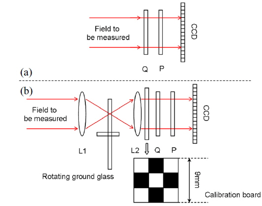
The traditional setup used to measure the polarization state of the field is shown in Fig. 1(a). By setting the quarter-wave plate Q and polarizer P angle as

Where
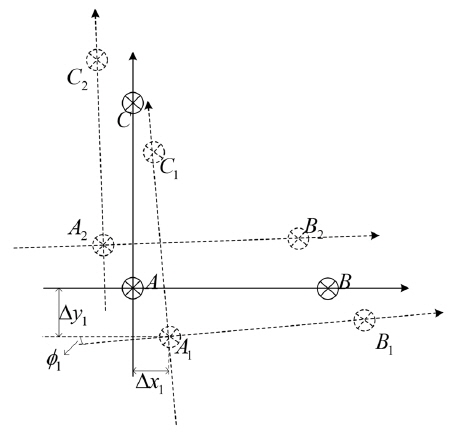
Without considering the distortion, factors analyzed above result in the images’ shift away from the original positions. A hypothetical case shown in Fig. 3 is used to illustrate this phenomenon.
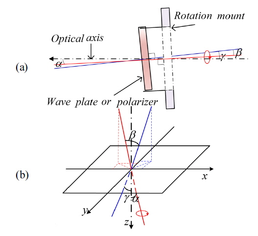
Assuming that we have rotated an angle

Where (
However, for an unknown vector field, there are no characteristic points that can used to match images. In order to calibrate values of the shifts (
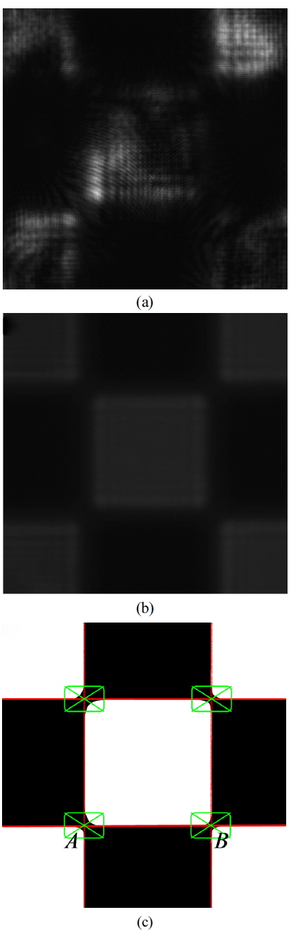
We first implemented binary conversion of Fig. 4(b) by setting a threshold value. We selected a 6 mm × 6 mm window in the acquired images. The reason of selecting a 6 mm × 6 mm window is the size of small lattices in the checkerboard is 3 mm × 3 mm. This means nearly half of the 6 mm × 6 mm window has transmittance 1, while the other half has transmittance 0. So the average gray value in the selected window can be used to implement binary conversion of Fig. 4(b). This value is proved to be very effective in our experiments. The threshold value μ is given as follow
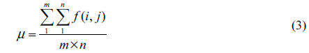
Where
In this section, we used the setup shown in Fig. 1(b) to measure a field with an array of PSs produced by superposition of three sources of linearly polarized light [19]. The polarization directions of two beams were perpendicular to one another, and polarization direction of the third beam had an angle 45° with polarization directions of the other two beams. The quarter-wave plate (AHWP10M) was offered by Thorlabs, and its thickness was 1.07 mm. The polarizer (LPVISB100) was offered by Thorlabs, and its thickness was 2.0 ± 0.2 mm. According to the detailed calibration procedure illustrated in the above section, we obtained the values (
In our experimental data, the values of
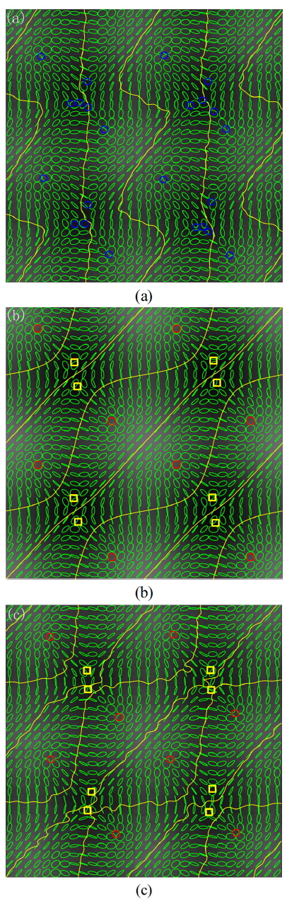
The Fig. 5(c) was the same area shown in Fig. 5(a), while the distribution of polarization state in Fig. 5(c) was obtained after the procedure of eliminating the shifts. The vector field is divided into band structure with periodic distribution of -1/2 Stars [yellow squares in Fig. 5(c)] and +1/2 Lemons [red circles in Fig. 5(c)]. The polarization may be either right handed or left handed, but C points of opposite handedness are always separated by an L-line [4]. Compared with the numerical simulation, Fig. 5(c) had basically the same distribution of polarization states, apart from sharp teeth on the L-lines. These sharp teeth were caused by noise. The comparison of Fig. 5(a), (b) and (c) illustrated that the method we proposed can calibrate and eliminate the mismatches caused by the rotating devices, and this method is feasible in practical experiments.
Many papers acquired good experimental results [13-16] without eliminating the mismatches caused by the measuring system. But we noticed that most of these successful experiments were measuring the polarization state of fields with sparse PSs. Mismatches were too small to disturb the distribution of polarization states, and they could be ignored. For example, the distance is smaller than 0.2 mm in our experiment. However when measuring the field with rapidly varying distribution of polarization state (such as a field with intensive PSs), the mismatches may be big enough to destroy the distribution of polarization states, for example, the cases in [17], [18] and [19]. Analyzing from the data, we noticed that the size of field shown in Fig. 5(c) was about 1735 μm × 1735 μm and the density of PSs was about 5.6 / mm2. The distance of the nearest two PSs in Fig. 5(c) was about 100 μm, which was smaller than the mismatch that occurred between
It is worthwhile to notice that the mismatches cause more serious effects in fields with higher density of PSs. As shown in Fig 5(a) and (c), the isolated Lemons in Fig. 5(c) maintained their type in Fig. 5(a), while the dense Stars in Fig. 5(c) transformed into several C-points in Fig. 5(a). In other words, for a field with sparse PSs, someone may obtain the right experimental results without calibrating the shifts. However when used to measuring field with crowded PSs, the calibration technique is necessary. However what kind of density of PSs can be regarded as crowded PSs (or sparse PSs) has not been definite. But one thing is certain: if the biggest mismatch between images is close to (or bigger than) the distance of the nearest PSs in the measured field, the calibration is necessary.
In addition, the method requires that the polarization components be removed from the optical path to measure the original image, so the calibration procedure should be repeated when the system is used to measure a new field.
In this paper, we propose a measuring system used to measure the polarization state of a field. This method can calibrate the shifts caused by rotating quarter-wave plate and polarizer through constructing characteristic points in the measured light with a checkerboard calibration board. The more serious obstruction of the mismatches occurs in a field with more intensive PSs. In the setup, a combination of a rotating ground glass and two lenses is used to reduce the coherence of light, and it also ensures uniform distribution of intensities obtained by the CCD. The effect of the combination makes it possible to extract the characteristic points of the checkerboard. According to coordinate values of the characteristic points, we acquire the rotated angle and panned distance when light passes through the quarterwave plate and the polarizer. By eliminating the shifts, we retrieve the original position of images, which ensured the correctness of calculation of the polarization state. Then a field with an array of PSs is measured. The data shows that the mismatches were big enough to result in wrong distribution of polarization state, and thus it is necessary to eliminate the mismatches. Compared with the numerical simulation, the experimental result has the same distribution of polarization states with the simulation, which illustrated the feasibility of this method. Though our results are obtained from measuring the specific three-wave interference, it is clear that our experimental method can be readily generalized to more general cases.