Fiber gratings, such as fiber Bragg gratings and long-period fiber gratings (LPFGs), have been significantly advanced in optical communication systems and optical sensors because of their many advantages, such as wavelength-selective nature, high tunability, electromagnetic immunity, etc. [1-5] LPFGs can basically couple a fundamental core mode to the forward propagating cladding modes resulting in harmonic resonant peaks in the transmission spectrum. Cladding modes play an important role in realizing fiber-optic sensors based on LPFGs with high sensitivity to external perturbation change, such as temperature and strain [1-3]. There is much research on the development of fabrication techniques of LPFGs [6-19]. A conventional LPFG can be simply fabricated by exposing single-mode fibers (SMFs) with a germanium-doped core to UV excimer lasers and frequency-doubled argon lasers [1]. For specialty fibers without photosensitivity, such as photonic crystal fibers (PCFs), different fabrication techniques are required to generate the periodic index modulation for the realization of LPFGs [2, 6-19]. The etching method to induce the periodic deformation of the silica cladding in the dispersion-shifted fiber (DSF) was proposed by using a hydrofluoric acid (HF) solution incorporating the metal coating procedure [16]. However, it is not easy to make symmetrical and periodic metal coating layers on the cylindrical cladding of the DSF. Recently, two fabrication techniques of LPFGs including a thick photoresist and an inductively coupled plasma technique were proposed [17, 18]. In the previous two methods, however, a sacrificial copper layer was first coated on the wafer resulting in the induction of additional loss. It is not evident if the two previous methods are capable of deeply corroding the silica cladding of an optical fiber because the reduction of the cladding diameter of the optical fiber was preprocessed. This means that the previous methods cannot readily fabricate the LPFG using a conventional SMF with lower photoelastic effect than the DSF. The periodic polymer patterns still remained in the surface of the LPG after etching the silica cladding [17]. The inductively coupled plasma (ICP) method may not be capable of deeply etching the silica cladding of the optical fiber [18]. Therefore, it is still necessary to consider a fabrication technique of LPFGs based on the regular SMFs with a low photoelastic coefficient.
In this work, we discuss transmission characteristics of LPFGs fabricated by periodically etching a conventional SMF. The silica cladding of the regular SMF is periodically removed by using a wet etching technique incorporating the doublelayered photoresist coating overlay. The periodic deformation in the cladding of the SMF induces the periodic index modulation based on the photoelastic effect when tensile strain is applied and consequently generates the resonant peak wavelengths in the transmission spectrum resulting from the mode coupling between the core and cladding modes in the LPFG. The effects of ambient index and torsion on the resonant wavelength and the extinction ratio of the proposed LPFG are presented. The torsion-induced birefringence changes polarization-dependent loss (PDL) of the proposed LPFG.
II. FABRICATION OF THE SMF-BASED LPFG
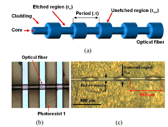
Figure 1(a) indicates the structure of the proposed LPFG with periodic micro-ridges in the cladding region of the conventional SMF. It is important to symmetrically remove the silica cladding of the SMF because of its cylindrical structure. Photoresist with a thickness of 150 μm was spin-coated on the substrate. Then we put a conventional SMF on the substrate with photoresist and recoated it with the same photoresist with a thickness of 150 μm. The prebaking process was taken to remove the solvent in photoresist. To remove photoresist periodically, we exposed the SMF with photoresist to a UV lamp through an amplitude mask. The length and the period of the amplitude mask were 20 mm and 650 μm, respectively. Since photoresist exposed to a UV light is readily eliminated by using a developer, the symmetric and periodic photoresist pattern was imprinted on the surface of the SMF. Figure 2(b) shows the photograph of the SMF with symmetrical and periodic photoresist patterns after the developing process. The SMF with the periodic and symmetric photoresist patterns was immersed in the hydrofluoric acid solution to remove the silica cladding that was not covered with photoresist, which results in the reduction of the diameter of the SMF. Since the periodic photoresist patterns effectively prevent the silica cladding of the SMF from being corroded by the hydro-fluoric acid solution, the diameter of the SMF with photoresist patterns should be less reduced than that without photoresist patterns. The periodic and symmetric micro-ridges on the surface of the SMF were finally achieved. Figure 2(c) shows the photograph of the fabricated LPFG based on the SMF measured by using an optical microscope. The grating period (
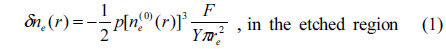
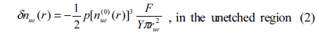
Since the etched and the unetched regions in Fig. 1(a) have different radii,


where
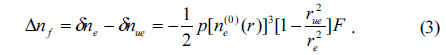
It is evident that the value of Δ

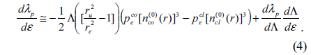
It is obvious that the negative contribution of the photoelastic effect to the strain-dependence of the resonant wavelength of the LPFG compensates the positive waveguide dispersion term in Eq. (4). Consequently, the resonant wavelength shift of the proposed LPFG with variations in strain can be negligible. Compared to the strain sensitivity of the LPFG with periodic micro-ridges, the variation of the waveguide dispersion with respect to torsion change is negligible and the torsion sensitivity of the LPFG (
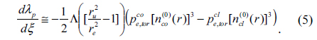
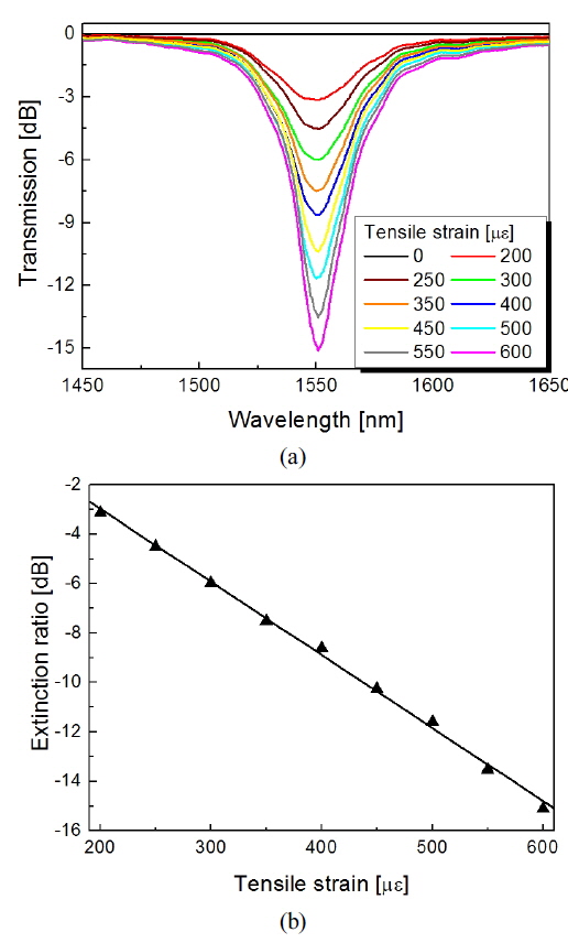
Therefore, the resonant wavelength of the LPFG with periodic micro-ridges shifts to shorter wavelength as the applied torsion increases. Figure 2(a) depicts the transmission characteristics of the proposed SMF-based LPFG with variations in strain. The mode coupling between core and cladding mode based on the photoelastic effect is gradually induced by increasing strain resulting in the enhancement of the extinction ratio at a resonant wavelength. Figure 2(b) exhibits the variation of the extinction ratio as a function of the applied strain. The variation of the extinction ratio at a wavelength of 1550.8 nm was measured to be -15.1 dB when the applied strain was 600 με. However, the resonant wavelength of the LPFG was not changed severely by the applied strain because of the simultaneous induction of the photoelastic effect in the core and the cladding regions. Since the applied strain identically changes the effective refractive indices of the core and the cladding modes, the positive waveguide dispersion factor will be compensated by the negative photoelastic effect induced by strain. Therefore, the resonant wavelength shift of the proposed LPFG with variations in strain is rarely observed as the mode coupling between the core and the cladding mode occurs. It is manifest that it is possible to monitor the external strain change by detecting the extinction ratio of the proposed LPFG with variations in strain.
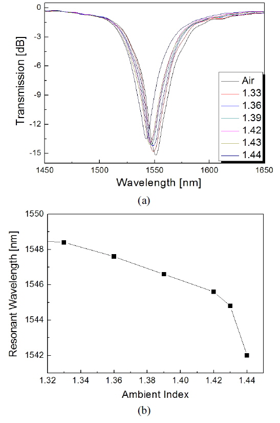
Figure 3(a) and 3(b) indicate the transmission spectra and the resonant wavelength shift of the proposed SMF-based LPFG, respectively, with variations in ambient index. Since the effective index of the cladding mode is increased by ambient index, the resonant wavelength of the LPFG must be shifted to shorter wavelength as ambient index increases. The extinction ratio of the LPFG was degraded by ambient index because of the induction of the optical attenuation of the cladding mode. The ambient index sensitivity of the proposed SMF-based LPFG was measured to be -58.2 nm/RIU (RIU: refractive index unit).
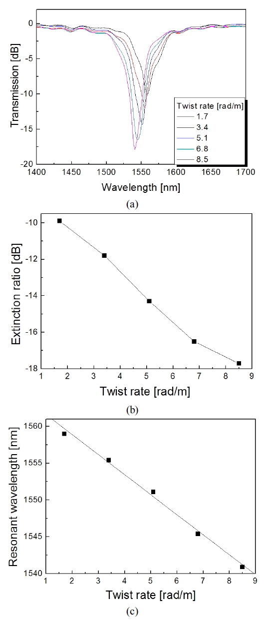
Figure 4(a) shows the transmission spectra of the proposed LPFG with variations in torsion. Since the torsion-induced photoelastic effect reinforces the coupling strength between the core and the cladding mode in the proposed LPFG, the extinction ratio should be enhanced by increasing torsion. Since the refractive index variation based on the torsion-induced photoelastic effect is much higher than that based on the tensile strain-induced one and the torsion sensitivity of the LPFG is negative, the resonant wavelength shift of the LPFG with variations in torsion is apparently observed in the transmission spectra [20]. As seen in Fig. 4(b), the resonant wavelength of the LPFG shifts to shorter wavelength as the applied torsion increases.
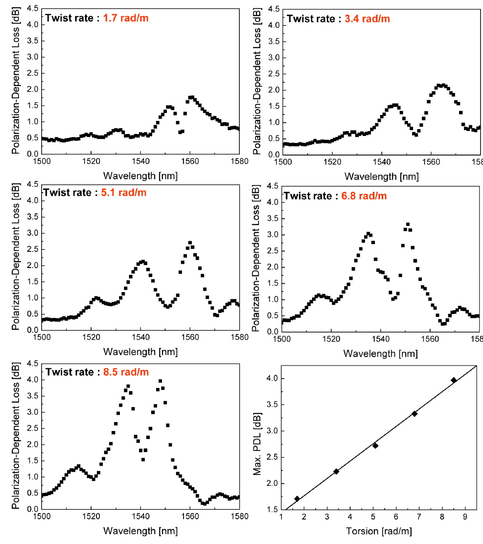
Figure 5 shows the variation of PDL of the proposed SMF-based LPFG with variations in torsion. The PDL is closely related with the birefringence of the optical fiber. The torsion-induced elliptical birefringence resulting from different amount of twist rate in etched and unetched cladding regions increased PDL of the LPFG as seen in Fig. 5. The PDL can be defined as the maximum variation of the transmitted power for all possible polarization states. The applied torsion to the proposed SMF-based LPFG will give rise to an elliptical birefringence within the SMF-based LPFG because the induction of shearing force and twisting strain in the SMF. Since the variation of the elliptical bire-fringence vector is directly proportional to the external torsion [21, 22], the effective indices of the etched and the unetched regions should be distinctly changed by the external torsion resulting in two different resonant wavelengths depending on two eigen polarization states. The amount of the PDL is predominantly determined by the wavelength spacing of two resonant wavelengths based on two orthogonal polarization states. Consequent, the induction of the elliptical birefringence by the external torsion will definitely increase the amount of the PDL of the proposed SMF-based LPFG because of the torsion-induced elliptical birefringence changes the wavelength spacing of two resonant wavelengths based on two orthogonal polarization states. For a torsion of 8.5 rad/m, we measured the amount of PDL of the LPFG to be 3.9 dB.
We discussed transmission characteristics of the LPFG manufactured by symmetrically and periodically etching a conventional SMF. The double-layered photoresist overlay was formed in the surface of the SMF to engrave periodic and symmetrical micro-ridges on the surface of the SMF. Tensile strain applied to the SMF with periodic deformation in the cladding of the SMF successfully induced the periodic index modulation based on the photoelastic effect in the SMF. Consequently the resonant wavelengths resulting from the mode coupling between the core and the cladding mode in the SMF appeared in the transmission spectrum. The extinction ratio of the SMF-based LPFG was measured to be -15.1 at a resonant wavelength of 1550.8 nm when the applied strain was 600 με. The resonant wavelength of the LPFG was shifted to shorter wavelength by increasing ambient index because of the ascent of the effective index of the cladding mode. The extinction ratio of the LPFG was reduced by ambient index because of the increment of the optical attenuation of the cladding mode. The photoelastic effect based on torsion shifted the resonant wavelength of the LPFG to shorter wavelength. The polarization-dependent loss of the proposed LPFG was increased by torsion because of the torsion-induced birefringence. The PDL of the LPFG at a torsion of 8.5 rad/m was measured to be 3.9 dB.