In this paper we propose an improved version of the computational integral imaging reconstruction (CIIR) for visualizing a partially occluded object by utilizing an image inpainting technique. In the proposed method the elemental images for a partially occluded three-dimensional (3D) object are recorded through the integral imaging pickup process. Next, the depth of occlusion within the elemental images is estimated using two different CIIR methods, and the weight mask pattern for occlusion is generated. After that, we apply our image inpainting technique to the recorded elemental images to fill in the occluding area with reliable data, using information from neighboring pixels. Finally, the inpainted elemental images for the occluded region are reconstructed using the CIIR process. To verify the validity of the proposed system, we carry out preliminary experiments in which faces are the objects. The experimental results reveal that the proposed system can dramatically improve the quality of a reconstructed CIIR image.
Computational integral imaging (CII) is able to capture and reconstruct partially occluded 3D objects for 3D visualization and recognition [1-19]. CII consists of the pickup process and the subsequent computational integral imaging reconstruction (CIIR) process. In the pickup process, a 3D object is recorded as elemental images through a lenslet array. In CIIR, the elemental images are digitally processed using a computer, by which 3D images can be easily reconstructed at a desired reconstruction plane. This CII approach is very useful in the visualization and recognition of 3D objects which are partially occluded by interposed objects [13-20].
In the CII method for partially occluded 3D objects, the generally uncharacterized occlusion seriously degrades the resolution of the computationally reconstructed plane images, since it hides the 3D object to be recognized. Studies to address this problem [14-18] have been based on removing the occlusion from the recorded elemental images to obtain plane images of good visual quality. However, after the occluding object has been removed, corresponding holes remain in the elemental images. This may prevent us from obtaining good visual quality in the reconstructed images. In 2010, Jung et al. proposed an interesting reconstruction method for occlusion holes using optical flow and triangular mesh reconstruction [20]. However, even though reconstructed images can be obtained with high accuracy, the depth extraction algorithm is quite complex because it consists of image rectification, image sequence generation, depth segmentation, depth extraction, and triangular mesh reconstruction. This may impose high computational cost and slow reconstruction speed.
In this paper we propose an improved CII method that utilizes the image inpainting technique for visualization of a partially occluded object. The inpainting technique, which is widely used in two-dimensional image and video processing, is a quite simple and robust method that allows for calculation in real time [21, 22]. The proposed method fills in the missing data for the occluded region with an inpainting technique that uses information from the neighboring pixels. The inpainting technique fills in the data in such a way that the occluded region is recovered. With the missing data filled in, the CIIR can reconstruct a 3D image that is faithful to the original 3D image, prior to occlusion. To verify the validity of the proposed system, we perform preliminary experiments in imaging faces and present the results.
II. CIIR METHOD USING IMAGE INPAINTING
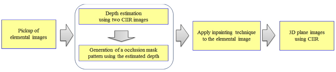
We want to improve the visual quality of the 3D plane images obtained from the CIIR process, for applications involving 3D visualization and recognition of partially occluded objects. To do so, we use both an occlusion removal technique [20] and an image inpainting technique [21] to generate modified elemental images without occlusion. The proposed method is mainly composed of four different processes, as shown in Fig. 1.
2.1. Pickup of a Partially Occluded 3D Object
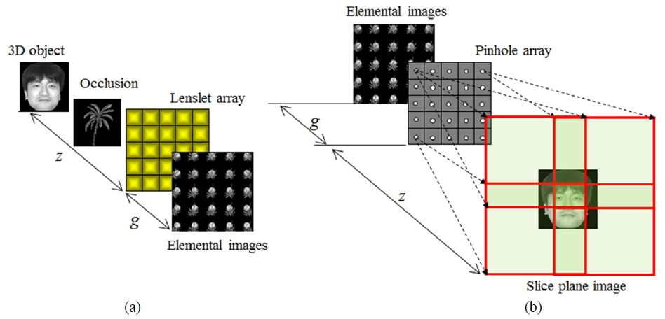
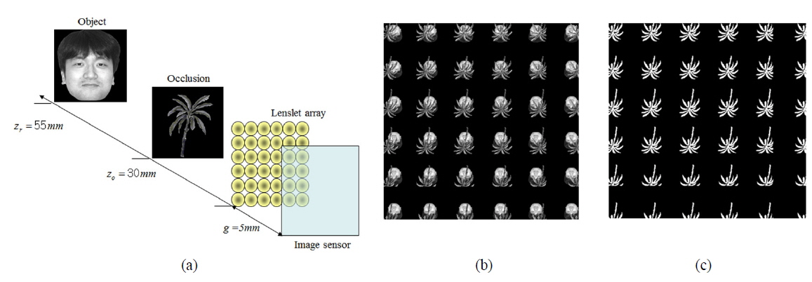
The first process is the pickup of the partially occluded 3D object, as shown in Fig. 2(a). The 3D object of interest and the occluding object are located respectively at two arbitrary distances. They are recorded through the lenslet array using a digital camera. These recordings are called
2.2. Estimation of the Occluded Area
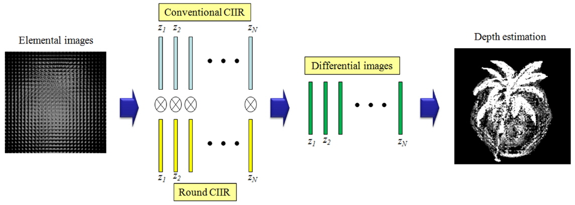
The second process in the proposed method is the estimation of the occluded area in the elemental images. Here we want to estimate the position of the occlusion to generate the weight mask pattern used in the next process. To do this, the occlusion is estimated by the method in [20], which uses two different kinds of CIIR. In this method two different sets of plane images are generated, and the absolute differences between the two plane images are calculated. In this paper, the CIIR methods based respectively on square mapping and round mapping are used. These CIIR methods are well described in Ref. [20].
The main principle of depth estimation is as follows: The elemental images are processed by the two different CIIR methods, as shown in Fig. 3. Then we can generate two different plane image sets, using the square mapping and round mapping methods. After obtaining the plane images we calculate the absolute difference images between the two plane image sets, as shown in Fig. 3. Next we use the difference images to estimate the depth of the occlusion, and then we find the best estimate of the depth of the occlusion, based on the fact that the plane image reconstructed at the original position of a 3D object is obtained clearly, regardless of the mapping model. That is, the differential image for a clearly reconstructed plane image is composed of many low-intensity pixels; on the other hand, the differential image for a blurred plane image has many high-intensity pixels. Based on this principle, we can estimate the depth of a 3D object by searching for the minimum pixel intensity among the differential images. Finally, we can find the occlusion’s position and shape from the estimated depth using a proper threshold value, and generate the mask’s elemental images via the computational pickup process of integral imaging [15].
2.3. CIIR Using Image Inpainting
As the next step, we introduce an image inpainting technique to the recorded elemental images. Image inpainting refers to the technique that automatically reconstructs the region from which image information is missing [21]. This technique uses information from the boundary that surrounds the missing region. The central problem of image inpainting can be divided into two main parts: first, how to define the missing region, and second, how to utilize the boundary information to fill in the missing region. In this study we use the image inpainting technique to fill in the unwanted occluded region with reliable data, using the data from the outer boundary of the occluded region [21]. Since the result of image inpainting depends on the boundary data, it is crucial to define well the outer boundary. We use the following steps to obtain a reliable boundary.
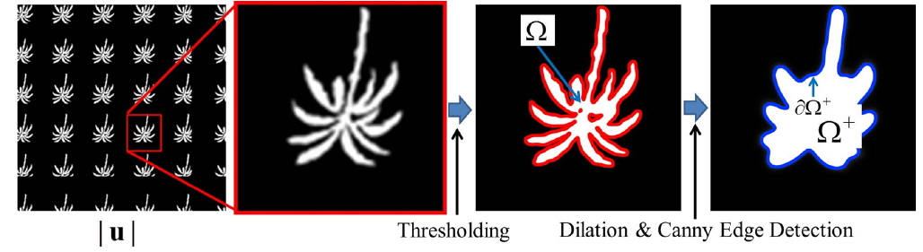
1. Perform thresholding on the depth map u obtained by the method in section 2.2, to obtain a binary map that describes the occluded region Ω. 2. zPerform a binary dilation operation on the binary map, to obtain an extended occluded region Ω+. 3. Obtain the boundary ∂Ω+ of the region Ω+. The first step, i.e. obtaining the occluded region Ω,
The first step,

where max(
Equation (1) extracts the region for which the depth map has a value larger than the predefined threshold value
After obtaining the binary domain Ω, we dilate it to obtain the region Ω+:

Finally,

The reason to extract the boundary of the dilated region Ω+, rather than the region Ω, is to ensure that the boundary contains no data from the occluded object, i.e. to ensure that only reliable data is painted into the occluded region. Figure 4 illustrates the relationships between u, Ω, Ω+, and the extended boundary
With
In other words, we fill in the region of the elemental image array corresponding to the region Ω+ of the mask image, using the data from the extended boundary

Here

and

The term is the L-2 norm calculated in the region
The parameter
The minimizer can be solved by a DCT-based iterative method:

where DCTN and IDCTN denote the

where the operator ÷ denotes element-by-element division, 1
where
After performing the image inpainting technique expressed in Eq. (8), and applying the resulting weight mask pattern to the original elemental images, we can obtain the modified elemental images where the occlusion is recovered using similar information from the original 3D object.
The final process of the proposed method is to reconstruct the 3D plane images for 3D visualization. The modified elemental images are used in the CIIR method as shown in Fig. 2(b), and then the improved plane images of good visual quality are reconstructed.
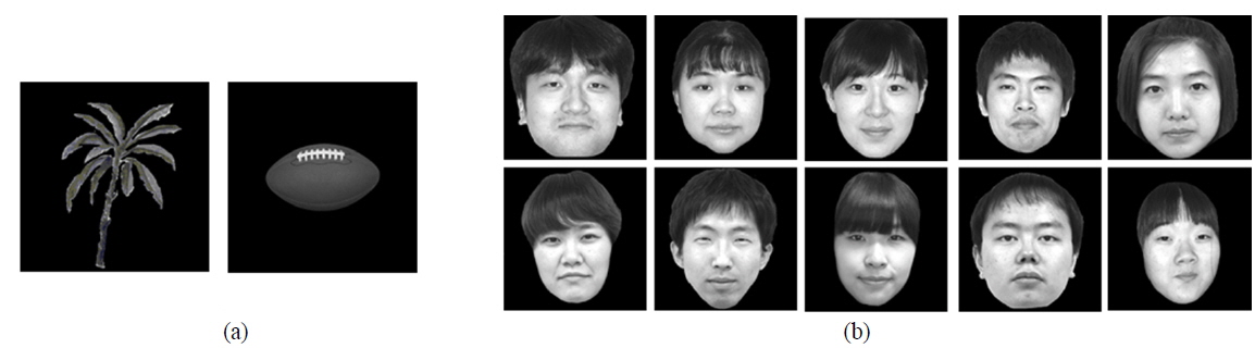
To verify the proposed method, we performed preliminary experiments. Figure 5 shows the experimental setup. We modeled the experimental setup computationally; the pickup experiments are performed by computer. We used two images (‘ball’ and ‘tree’) for the unknown occlusion and ten ‘face’ images for the target 3D object, respectively. The two occlusion images and ten ‘face’ images are shown in Fig. 6; they are located 30 mm and 55 mm from the lenslet array, respectively. First we recorded elemental images for the partially occluded ‘face’ object, using a lenslet array with 6×6 lenslets, each 5 mm in diameter. With this lenslet array we obtained elemental images with 900×900 pixels, as shown in Fig. 5(b).
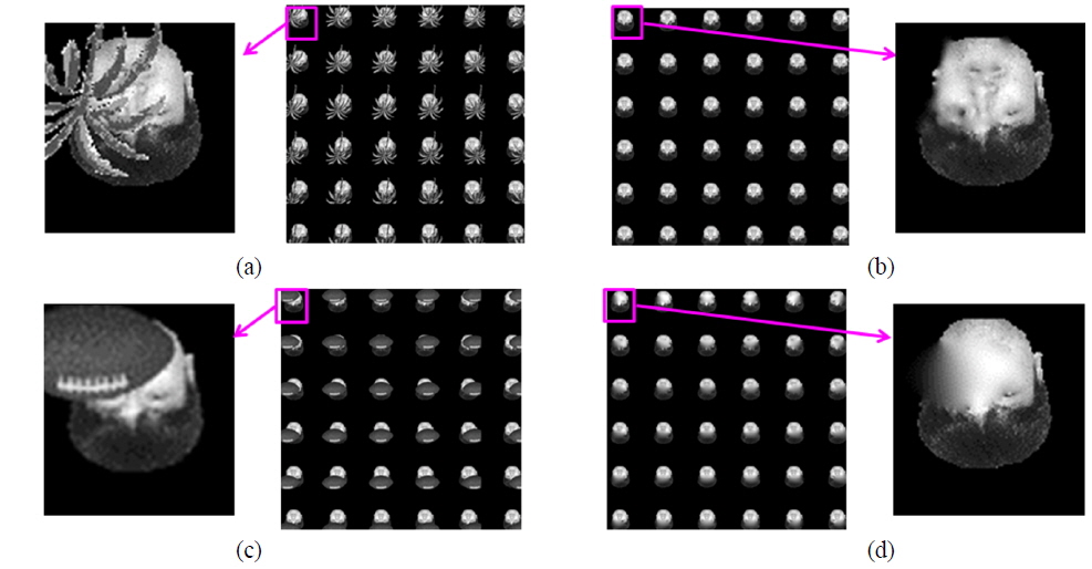
The recorded elemental images were employed in the second process of occlusion estimation, to get the binary weight mask pattern for the subsequent image inpainting. Here we generated two sets of plane images using two different CIIR methods, based respectively on the square and round mapping models. The weight mask pattern from our depth estimation process is shown in Fig. 5(c). Next the image inpainting technique was applied to the elemental images, on the basis of the weight mask pattern. Figures 7(a) and 7(c) show the results of the original elemental images for both ‘tree’ and ‘ball’ occlusions, while the elemental images obtained from the proposed image inpainting technique are shown in Figs. 7(b) and 7(d) respectively. With these elemental images we reconstructed the 3D plane images using the CIIR methods.
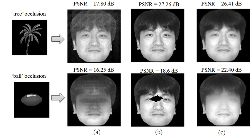
Figure 8 shows plane images for the first ‘face’ image, for two different occlusions. In the results in Fig. 8(a) reconstructed from the elemental images with occlusion using the original CIIR [3], we can see that both occlusions produce serious image noise in the reconstructed images. For comparison, we reconstructed 3D plane images with the occlusion-removed elemental images using the CIIR method of Ref. [20], which utilized a modified CIIR method with a normalization process after occlusion removal. The performance of that CIIR method is very sensitive to the occlusion pattern, and thus may produce serious image errors if the occlusion is heavy or complex. The plane images reconstructed using the method proposed in Ref. [20] are shown in Fig. 8(b). When the ‘tree’ occlusion was used, the reconstructed image was similar to that from our method. However, we can see serious distortions in the reconstructed image when the ‘ball’ occlusion was used. This is because the normalization process used in Ref. [20] cannot reconstruct a proper plane image for a totally occluded spot in the elemental images. On the other hand, our proposed method can reconstruct plane images of the good visual quality, as seen in Fig. 8(c).
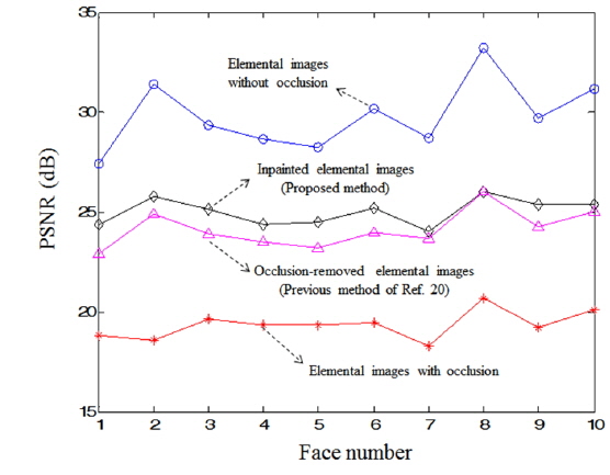
To evaluate our method objectively, the peak signal-to-noise ratio (PSNR) was calculated for all reconstructed plane images. Figure 9 shows the average PSNR results for ten face images with two different occlusions. Four different cases are presented in Fig. 9. We obtained a high PSNR improvement of approximately 5.66 dB on average, compared to using elemental images with occlusion. In addition, the PSNR was improved by approximately 0.88 dB over that for the method of Ref. [20]. The results in Figs. 8 and 9 show that our method is superior to the conventional methods, in terms of visual quality.
In conclusion, we have proposed an improved method using an image inpainting technique to obtain the CIIR image of a partially occluded object. Since the occlusion produces serious image noise in the reconstructed image, we removed the occlusion and inpainted reliable boundary information into the occlusion holes using the image inpainting technique. By doing so, the proposed method dramatically improves the image quality of the reconstructed image. To verify our method, we performed preliminary experiments on images of faces. From the experimental results, we obtained a high PSNR improvement of approximately 10 dB on average. We expect that the proposed method can be useful in numerous applications, such as 3D object visualization and recognition.


![(a) Reconstructed plane images from elemental images with occlusion using the original method of Ref. [3]. (b) Reconstructed plane images using the method of Ref. [20]. (c) Reconstructed plane images using the proposed method.](http://oak.go.kr/repository/journal/15892/E1OSAB_2015_v19n3_248_f008.jpg)