We experimentally demonstrated a novel wavelength-swept laser using a cascaded Raman gain around 1310 nm. A 1064/1310 wavelength division multiplexing (WDM) coupler and coupled fiber Bragg gratings mirrors at 1064, 1117, 1175, 1240 nm are effectively used to increase the power efficiency in a laser ring cavity with highly non-linear fiber (HNLF) of 2 km. Linear wavelength sweeping is demonstrated with the 100 Hz triangular driving signal to fiber Fabry-Perot tunable filter (FFP-TF) around the 1310 nm region. The measured sweeping range and output power were 27 nm and 2.1 mW, respectively, which are suitable for optical coherence tomography (OCT) imaging.
Wavelength-swept lasers have formed important light sources for optical coherence tomography (OCT) imaging [1-3] and fiber Bragg gratings (FBG) optical sensor applications [4]. The critical factors of swept-source OCT (SS-OCT) imaging depend on the central wavelength region, spectral tuning range and sweeping speed of the wavelength-swept laser. The central wavelength region of the wavelength-swept laser is selectively decided in accordance with the biological application in question as scattering and absorption losses in tissues vary significantly with the light wavelength [1, 2]. The spectral tuning range of the wavelength-swept laser should be increased to improve the axial resolution of SS-OCT imaging [3]. The sweeping speed of the wavelength-swept laser is also important to improve the acquisition speed of SS-OCT imaging [5, 6]. Since the central wavelength region and spectral tuning range of the wavelength-swept laser are determined by the gain medium in the laser cavity, various gain media such as semiconductor optical amplifiers (SOAs) [1-4], erbium-doped fiber amplifiers (EDFAs) [7], ytterbium-doped fiber amplifiers (YDFAs) [8], fiber optical parametric amplifiers (FOPAs) [9], and fiber Raman amplifiers (FRAs) [10] have been employed in the last decade. The central wavelength region of an SOA can be selected from various gain windows of 800 nm, 1060 nm, 1310 nm, and 1550 nm. However, a broad spectral tuning range of the SOA can only be achieved with multiple SOA chips because the gain bandwidth of the SOA is limited by its material properties [4]. The EDFA and YDFA have indigenous central wavelength regions of 1550 nm and 1060 nm, respectively, along with a limited spectral tuning range around their central wavelengths [7, 8]. FOPAs can reportedly provide broad gain windows; however, this requires extraordinarily high pump power of over tens of watts [9].
Recently, we have proposed the use of the FRA to implement a wavelength-swept fiber Raman laser operating around the 1550 nm region using optical pumping sources in the range of 1425 nm to 1465 nm [10, 11]. The FRA offers advantages such as the instantaneous carrier relaxation time of stimulated Raman scattering and arbitrary gain band selection by the wavelength of the optical pump sources. However, to the best of our knowledge, most wavelength-swept fiber Raman lasers have been implemented around the 1550 nm region because high-power optical pumping sources are commercially available only in the range of 1425 nm to 1465 nm [10-13]. Meanwhile, 1550 nm-centered wavelength-swept fiber Raman lasers find very little use in biomedical OCT applications because there is no specific biological merit offered by lasers operating in the 1550 nm region. A P-doped fiber has been used as Raman gain medium to simplify schematic design and obtain high efficiency [14-17]. In this case, however, a specific wavelength region of 1240 and 1480 nm can be obtained for the first and second Stokes respectively by the use of a 1064 nm pumping wavelength. Thus the P-doped fiber is not useful for the 1310 nm-centered wavelength-swept Raman fiber laser.
In this research, for the first time, we implemented a 1310 nm-centered wavelength-swept fiber Raman laser in the light of the preferential use of the 1310 nm wavelength region for dermatological OCT applications. When incident on human skin tissue, laser wavelengths centered on 1310 nm provide less scattering loss than those centered around 800 nm or 1060 nm and less absorption loss than that obtained with a central wavelength of 1550 nm [1-3]. For the implementation, an optical pumping source operating around the 1240 nm region is necessary for the 1310 nm-centered wavelength-swept Raman fiber laser, but commercially available pumping power in the 1240 nm region is limited. Our novel cavity design yielded high FRA around the 1310 nm region with the use of a 1064 nm pumping source that provided cascaded fourth-order Raman gain. To increase the pumping efficiency, a 1064/1310 nm wavelength-division multiplexing (WDM) coupler and coupled FBG mirrors reflecting wavelengths of 1064, 1117, 1175, and 1240 nm were optimally used in a laser ring cavity. Cascaded Raman fiber lasers can form a convenient alternative gain medium in the 1310 nm region as well as other wavelength regions as they provide highly efficient architecture [18].
II. WAVELENGTH SWEPT CASCADED RAMAN FIBER LASER
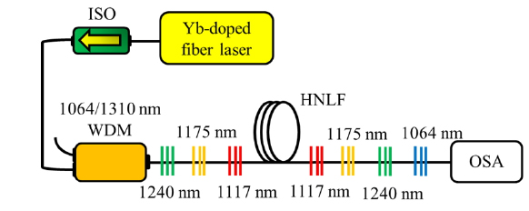
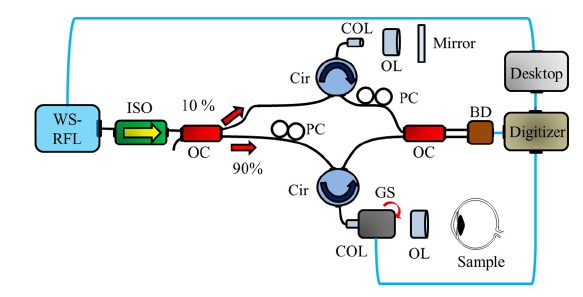
Figure 1 shows the schematic of the cascaded Raman amplifier for the 1310 nm gain region. The Raman amplifier consists of a 1064 nm Yb-doped fiber laser, a 1064/1310 nm WDM coupler, a 2 km long highly nonlinear fiber (HNLF), coupled FBG mirrors, and an optical isolator. The original optical pumping at 1064 nm is generated from the continuous-wave Yb-doped fiber laser, which has a maximum output power of ~20 W. The optical isolator is used to achieve unidirectional propagation of light in order to avoid the generation of standing waves in the resonance cavity. The coupled FBG mirror pairs that have Bragg wavelengths of 1117, 1175, and 1240 nm are placed on both sides of the HNLF. The reflectivity of most FBGs was greater than 95%. The 3 dB bandwidths of 1064 nm, 1117 nm, 1175 nm and 1240 nm’s FBGs were 12, 0.6, 0.9 and 0.6 nm, respectively.
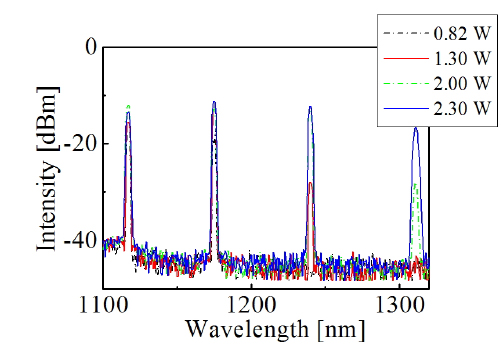
In addition, an FBG that has a Bragg wavelength of 1064 nm is placed at the end of the laser cavity to reflect high-power optical pump light. This linear laser cavity with seven FBGs is designed to effectively generate a cascaded fourth-order Raman-Stokes gain in the 1310 nm region. Since a broad amplified spontaneous emission (ASE) gain around the 1310 nm region is necessary to realize the 1310 nm-centered wavelength-swept fiber Raman laser, the lasing beam at 1240 nm (via the coupled 1240 nm FBG mirrors) is used as a high-power optical pumping source for ASE generation in the 1310 nm region. Figure 2 shows the cascaded Raman amplifier output spectra of the first-, second-, third-, and fourth-order Stokes waves. Initially, the HNLF is pumped by the Yb-doped fiber laser, and optical signals at the first Stokes frequency are generated by stimulated Raman scattering. When these signals continue to propagate along the fiber, they serve as a pump for second-order Stokes waves. While increasing the pump power, these processes are repeated to obtain higher-order Stokes waves. From the experiment with the 2 km long HNLF, the cascaded first-order (1117 nm), second-order (1175 nm), third-order (1240 nm), and fourth-order Stokes (1310 nm) waves are obtained when the 1064-nm laser’s pump power is 540 mW, 820 mW, 1.7 W, and 2.3 W, respectively.
Considering the interaction between the pump light and Stokes waves, the generation of the instantaneous Stokes intensity is proportional to the optical pumping power and the stimulated Raman gain coefficient [18-21]. With increase in the length of the HNLF, the stimulated Raman gain coefficient can proportionally increase; however, the increased fiber loss coefficient at the Stokes wavelength suppresses the generation of the instantaneous Stokes intensity. Therefore, within the limits of the given length of the HNLF and the limited optical pump power, it is important to increase the path-length efficiency by applying a feedback cavity structure. Since each cavity round-trip across the HNLF is optimally induced from the pairs of the FBG mirrors at 1064, 1117, 1175, and 1240 nm, the required pump power to increase the Stokes intensity can be effectively reduced, as can be inferred from the coupled equations of the cascaded Raman-Stokes shift [21]. When we remove the coupled FBG mirrors and adopt a ring cavity feedback structure based on the 1064/1310 nm WDM coupler only, a higher pumping power of more than 3 W is required to generate the fourth-order Stokes waves [18].
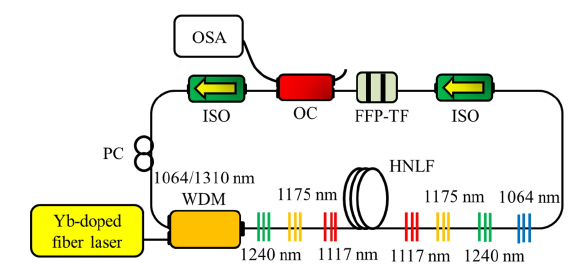
Figure 3 shows the schematic of the wavelength-swept fiber laser based on the cascaded Raman amplifier. The wavelength-swept cascaded Raman fiber laser consists of a Raman amplifier with optical gain around 1310 nm (Fig. 1), a fiber Fabry-Perot tunable filter (FFP-TF; Micron Optics), an 80:20 output coupler, two isolators, and a polarization controller (PC). The laser is coupled with the fiber ring resonance cavity via the 1064/1310-nm WDM coupler. Since the 1064/1310 nm WDM coupler exhibits a minimum cross-coupling ratio around 1064 and 1550 nm and a maximum cross-coupling ratio around 1310 nm, it is useful to combine the optical pumping beam at 1064 nm into the ring cavity and to induce the highest feedback efficiency around the 1310 nm region in the ring cavity [18]. In this research, linear cavity feedback using the pairs of FBGs is used to reduce the required pump power to shift from 1064 nm to 1310 nm, and the ring cavity feedback using the 1064/1310 nm WDM coupler is used to form a lasing cavity for the gain region around 1310 nm.
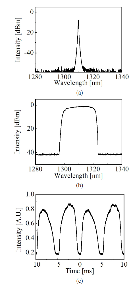
The above-mentioned setup can be used to select a lasing wavelength according to a driving electrical signal. A certain wavelength around the gain region of around 1310 nm can be swiftly selected for lasing via the transmission window provided by the FFP-TF. Figure 4 (a) shows the output spectrum of the laser at 1310 nm when the FFP-TF is fixed at a certain wavelength. The instantaneous linewidth is 0.18 nm and the signal-to-noise ratio (SNR) of the laser is larger than 50 dB. This high-quality lasing spectrum is due to the presence of the high-feedback-efficiency ring cavity around 1310 nm. Figure 4 (b) shows the optical output spectrum (peak-hold mode) of the wavelength-swept cascaded Raman fiber laser when a triangularly modulated driving signal of 100 Hz is applied to the FFP-TF. In this study, the measured sweeping range was 27 nm with the central wavelength of 1310 nm, and the extinction ratio was approximately 43 dB. The measured optical output power was 2.1 mW for a pumping power of 2.3 W. Figure 4 (c) shows the temporal transient intensity profiles of the wavelength-swept laser output with a sweeping rate of 100 Hz, which profiles were measured by an oscilloscope and a photo-detector. This optical output performance of the wavelength-swept cascaded Raman fiber laser makes the laser suitable as the light source of the SS-OCT for operation around the 1310 nm region. The limitation of current sweeping speed and output power is mainly caused from the long length of fiber cavity for the Raman gain generation. Since the roundtrip number is reduced for the longer length of HNLF and higher speed of FFP-TF, the output power will be decreased under the conventional wavelength-sweeping condition. The further investigations will be required to increase the sweeping speed by using the Fourier domain mode locked (FDML) method. When we use the optimized fiber length in cavity and corresponding speed of FFP-TF, the photon’s round-trip time can be matched with repetition time of FFP-TF for the increase of the output power under the FDML condition [4].
Figure 5 shows the experimental setup for SS-OCT imaging based on the proposed wavelength-swept cascaded Raman fiber laser. Two tunable directional couplers and two circulators were used to construct a Mach-Zehnder interferometer. The optimal optical power between the sample port and reflecting mirror port was controlled manually by means of the tunable directional coupler. A galvano mirror scanner was used for lateral scanning of the sample. The objective lens (LSM-03, Thorlabs) of 3x magnification and focal length of 54 mm was used for optimally gathering sample images. The converted reflecting intensities were recorded on a grayscale image as a function of the transverse and axial distances. Around 1024 depth points were acquired for the series of images, and each image was composed of 512 (axial) × 256 (transverse) pixels.
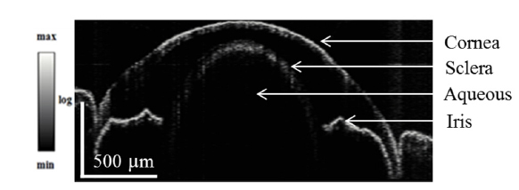
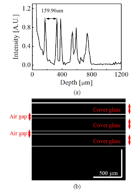
Figure 6 (a) shows a depth-encoded signal obtained using the discrete Fourier transform (DFT) for a sample comprising three cover glasses (4science, thickness of 160 µm) [22]. The measured thickness was 159.9 μm for the first cover glass. A two-dimensional (2D) OCT sample image was also obtained, as shown in Fig. 6 (b). All three cover glasses and the air gaps between the cover glasses can be clearly distinguished in the OCT image. The measured axial resolution was 28 μm, which exhibits reasonable agreement with the theoretical value. In addition, the measured transverse resolution was 39.7 μm. Figure 7 shows the cross-sectional OCT image of the eye sample of a small fish (Balantiocheilos melanopterus). A 2D OCT image was created from the Fourier transform of the corresponding 512 × 256 data set. The galvano scanner was driven at a frequency of ~0.19 Hz, and the acquisition time of the 2-D OCT image was 5.26 s.
In this research, we proposed and experimentally demonstrated a wavelength-swept cascaded Raman fiber laser operating in the 1310 nm region with a 2 km long HNLF and low pump power of 2.3 W. This was achieved using the optimal cavity structure of a 1064/1310 nm WDM coupler and coupled FBG mirrors reflecting wavelengths of 1064, 1117, 1175, and 1240 nm. When the FFP-TF was operated with a 100 Hz triangularly modulated signal, the wavelength-swept cascaded Raman fiber laser output exhibited a sweep range over 27 nm and an output power of 2.1 mW. When compared with the conventional wavelength-swept Raman laser source that is used for SS-OCT imaging around the 1550-nm region, we believe that our novel wavelength-swept cascaded Raman fiber laser operating around the 1310-nm region can provided improved OCT imaging. The further investigation will be necessary to improve the output power and speed by the use of the FDML method and increase the sweeping range by the use of broader 3 dB bandwidth FBGs [4].