This paper presents a new graphical method for selecting a pair of optical glasses to simultaneously achromatize and athermalize an imaging lens made of materials in contact. An athermal glass map that plots thermal glass constant versus inverse Abbe number is derived through analysis of optical glasses and plastic materials in visible light. By introducing the equivalent Abbe number and equivalent thermal glass constant, although it is a multi-lens system, we have a simple way to visually identify possible optical materials. Applying this method to design a phone camera lens equipped with quarter inch image sensor having 8-mega pixels, the thermal defocuses over −20℃ to +60℃ are reduced to be much less than the depth of focus of the system.
In recent optical instruments such as mobile phone and black box cameras, plastic materials are widely used. Because of their inherent temperature sensitivity, however, variation in ambient temperature significantly induces a change of refractive index, curvature of lens, and thickness. Since the thermal defocus caused by such changes degrades the image quality, a lens system using plastics should be designed to have stable performance over the specified temperature range.
To reduce thermal and chromatic errors, many design methods have been reported [1-8]. Perry studied the effect of temperature changes on optical performance in infrared optics. Rogers showed that the multi-lens system could be achromatized and athermalized with three materials by solving three equations, but it was difficult to find a proper combination of materials [5].
As alternative approaches to overcome these problems, graphic methods have been developed. Rayces and Lebich proposed a
In order to solve these difficulties, in this paper we introduce the equivalent Abbe number and equivalent thermal glass constant. Even though a lens system is composed of many elements, we can simply identify a pair of materials that satisfies the athermal and achromatic conditions, by selecting the corresponding materials for an equivalent lens from an athermal glass map. By application of the concept of equivalence to the phone camera lens composed of four elements, a good solution having small chromatic and thermal defocus is obtained. The chromatic error is ±10 µm between C- and F-lines, and the thermal defocuses over −20℃ to +60℃ are found to be much less than the depth of focus of the system. This lens is consequently achromatized and passively athermalized.
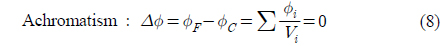
II. ATHERMAL AND ACHROMATIC CONDITIONS
For a single thin lens, the change in optical power (Δ

where
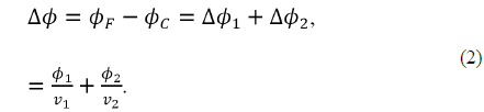
The analogous equation quantifying the power change of a doublet with wavelength is given by

For a doublet to be achromatic, each element is required to have power as follows:

As a result, by selecting proper Abbe numbers in Eq. (3), an achromatic system can be realized.
The variations of temperature change the radius of curvature, lens thickness and air spacing, and refractive index. These changes cause alignment errors and degrade the optical performance. An athermal system is meant to have stable optical performance, even during temperature changes in the optical system [9].
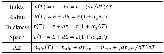
Thermal defocus is the change in the focus position on axis with temperature changes due to the variation of the index with temperature and the thermal expansion of the material. Table 1 lists the quantitative variations of design parameters due to temperature change [2].
[TABLE 1.] Variations of design parameters due to temperature change

Variations of design parameters due to temperature change
In Table 1, the parameters of
The change in optical power of a single thin lens due to a temperature change is given by

where,

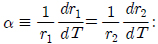
From Eq. (4), The change in optical power of a single thin lens is proportional to the thermal glass constant (

Inserting the achromatic condition of Eq. (3) into Eq. (5) results in an expression for the athermal and achromatic conditions for a doublet, as follows:

where
III. ATHERMAL AND ACHROMATIC DESIGN USING EQUIVALENT ABBE NUMBER AND THERMAL GLASS CONSTANT
By requiring a system to satisfy the equations for total power, achromatism, and athermalism, the athermal and achromatic solution can be found. For a system with an arbitrary number of elements, the following equations must be satisfied [10]:


All of these equations assume thin lenses in contact with each other. Although this is not a physically realizable solution, these equations can provide a good starting point. In the strictest sense, Equation (9) may include a term for thermal expansion of a housing material. However, the contribution of this term is so small compared to that of the material’s
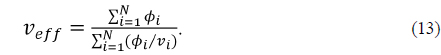
An athermal and achromatic doublet can be simply obtained from Eq. (6), however, it requires a very complicated process to have a lens system with many elements being athermal and achromatic simultaneously [7, 8]. In this study, the equivalent Abbe number(
For a given optical power, Equation (1) gives an expression for Abbe number:

Since the total power of a doublet is

Although two materials have different Abbe numbers, it can be defined as one valued Abbe number that is referred to as an equivalent Abbe number. In the same way, the equivalent Abbe number of a triplet thin lens in contact is given by
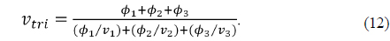
Extending this method to an
In common with equivalent Abbe number, equivalent thermal glass constant can be defined for a system with many elements. From Eqs. (4) and (5), equivalent thermal glass constant (

Also, the equivalent thermal glass constants of a triplet and an

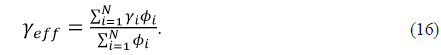
Although a system has an arbitrary number of elements, from Eqs. (13) and (16), Abbe number and thermal glass constant of a system can be simply obtained. Consequently, a pair of materials that satisfy the Eq. (6) can graphically be selected to simultaneously achromatize and passively athermalize an imaging lens. In this paper, the thermal glass constants for glasses supplied by Schott have been calculated, which are based on CTE and the variation of the refractive index with temperature [11-16].
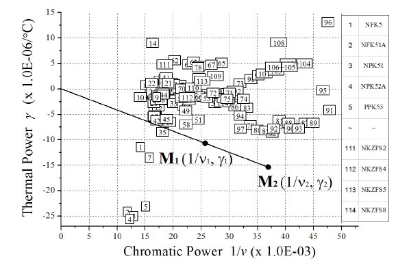
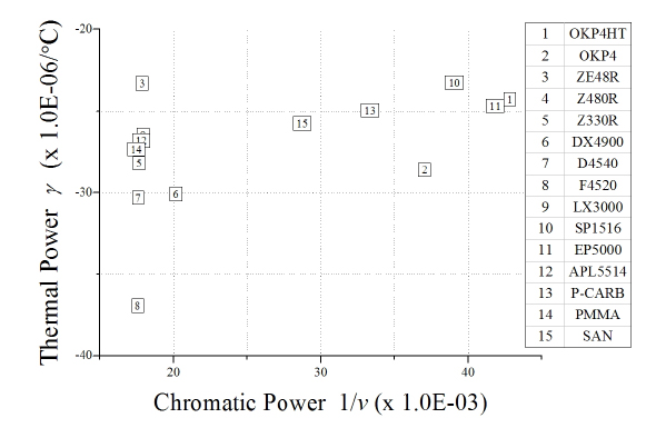
Figure 1 shows the athermal glass map for visible Schott glass. In Fig. 1, inverse Abbe number(1/
By plotting the thermal glass constant versus the inverse Abbe number, we can visually identify two materials that satisfy the athermal and achromatic conditions given by Eq. (6). In Fig. 1, any two materials(M1, M2) that can be connected by a line that passes through the origin will provide athermal and achromatic solutions. In other words, if one material is known on an athermal glass map, like M1(1/
IV. ATHERMAL AND ACHROMATIC DESIGN FOR A PHONE CAMERA LENS USING GRAPHICAL SELECTION OF GLASS PAIR
4.1. Analysis of a Starting Design
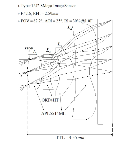
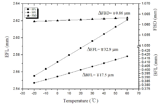
A phone camera lens composed of four plastics, equipped with a quarter inch image sensor having 8-mega pixels, is given as a starting case, as shown in Fig. 3. This lens has great thermal defocuses, as illustrated in Fig. 4, in particular, the variations for effective focal length(∆EFL) over −20℃ to +60℃ are ∓32.9 µm. However, note that the variations of flange back distance(∆FBD), depending on the thermal expansion and the length of a housing material which is of AL6061, is just ∓0.86 µm. This quantity is so small that the thermal defocus by the housing would be negligible, as pointed out in Section III. The starting lens fulfills many requirements of a current mobile phone camera, except color correction and stable thermal focus. In this research, however, the achromatic and passively athermalized design will be discussed using graphical selection of the materials.
4.2. Graphical Selection of a Material Pair and Optimized Design
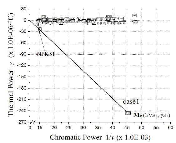
In a phone camera lens with four elements, three elements of L2, L3, and L4 are chosen such that they create an equivalent triplet, with equivalent Abbe number (
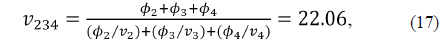
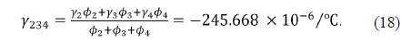
The equivalent triplet having
[FIG. 5.] Graphical selection of a glass material from the equivalent triplet on athermal glass map.

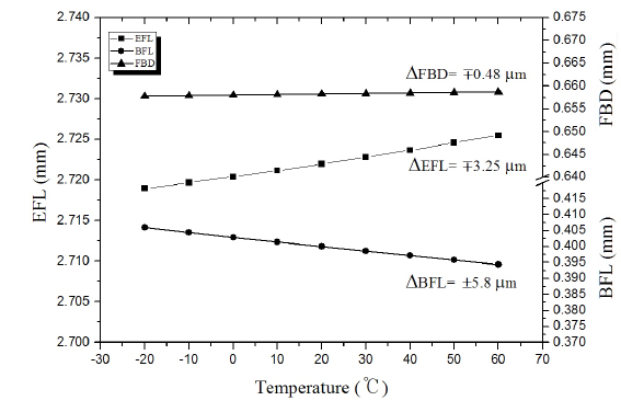
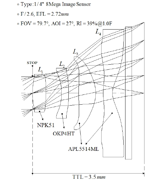
After replacing the first lens glass into NPK51 and bending, the starting lens has been re-optimized using Code-V. Finally, a lens for a phone camera having good performance is obtained, as shown in Fig. 6. This lens has small chromatic defocus less than ±10 µm between C- and F-lines. The thermal defocuses of this lens are significantly reduced, as illustrated in Fig. 7. The variations for effective focal length and back focal length over −20℃ to +60℃ are ∓3.25 µm and ±5.8 µm, respectively. Also, the variation of flange back distance is just ∓0.48 µm, which is much less than the quarter-wave depth of focus. This quantity is so small that the thermal defocus by the housing would be negligible. Thus, all thermal defocuses are much less than the depth of focus (

In conclusion, the designed lens is achromatic in visible light and passively athermalized over −20℃ to +60℃.
Figure 8 shows the modulation transfer function (MTF) characteristics of two lenses with temperature. The MTF of a designed lens from athermal and achromatic processes is much more stable than that of a starting lens over the specified range of temperature and more than 50 % at 110
By plotting the thermal glass constant versus the inverse Abbe number, athermal glass maps were derived for Schott glasses and plastic materials in visible light. For a lens system composed of many elements, we suggested the method of obtaining the equivalent Abbe number and equivalent thermal glass constant. By selecting the corresponding materials for an equivalent lens on an athermal glass map, we can simply identify a pair of materials that satisfy the athermal and achromatic conditions. This graphical method of selecting materials is a simple and powerful way to find a design solution. By utilizing the graphs and the concept of equivalence presented in this study, a good solution for a phone camera lens has been found. The finally designed lens has an f-number of 2.6, focal length of 2.72 mm, and good performances including stable thermal focusing. The expansion of an athermal glass map into a multi-lens system spaced element by element will be discussed in a following paper.