This study fabricated low thermal conductive polyacrylonitrile (PAN)-based carbon fibers containing cellulose particles while maintaining their mechanical properties. The high thermal conductivity of carbon fibers limits their application as a high temperature insulator in various systems such as an insulator for propulsion parts in aerospace or missile systems. By controlling process parameters such as the heat treatment temperature of the cellulose particles and the amount of cellulose added, the thermal and mechanical properties of the PAN-based carbon fibers were investigated. The results show that it is possible to manufacture composite carbon fibers with low thermal conductivity. That is, thermal conductivities were reduced by the cellulose particles in the PAN based carbon fibers while at the same time, the tensile strength loss was minimized, and the tensile modulus increased.
Because energy and global warming problems have emerged recently, interests have increased in high-strength, super-light materials capable of raising energy efficiencies. Consequently, carbon fibers with more than 92% carbon content are being widely used in various industrial areas as a super-light material with a high specific strength and a high specific modulus [1,2]. Particularly, due to the high dimensional stability, light weight and corrosion resistance as well as the excellent mechanical characteristics of carbon fibers, the applications of carbon fibers in transportation including aircraft have been greatly expanded [3]. Carbon fibers consist of graphite clusters where most SP2 carbon bonds are arranged in parallel with the axis of the fiber [4]. This is because these have a regular arrangement similar to that of single crystal graphite in the process of stabilization, carbonization and graphitization of the carbon fiber precursor. Due to such structural characteristics, carbon fibers maintain a high elasticity at elevated temperatures and are known as a material with excellent thermal stability because of characteristics such as high thermal conductivity and a very low thermal expansion coefficient [5].
There have been cases recently where some characteristics have been improved, or modifications have been made to match the characteristics to particular applications for use in broader areas [6]. For example, studies have been done in which the characteristics of composite materials are improved by growing carbon nanotubes onto carbon fibers [7-12], Additionally, there have been studies in which the mechanical properties and electrical conductivity of composite materials have been improved by improving the interfacial adhesion by coating the carbon fiber surfaces with graphene nanoplatelets [13].
Meanwhile, in the case of heat-resistant structures such as the engine nozzles of rockets, nuclear reactor structures, or rocket launch pads, etc., use of materials with a high modulus of elasticity and low thermal conductivity will be able to protect the internal engines of rockets from high-temperature operation environments. Therefore, studies are needed on carbon fibers with low thermal conductivity to achieve both heat resistance and heat insulation. Because the thermal conductivities of carbon fibers vary depending on the starting materials [14-17], different starting materials will enable the development of carbon fibers with low thermal conductivity. According to the literature on thermal conduction characteristics as a function of the starting materials, rayon-based carbon fibers heat-treated at 1500 K have about 20.5% of the thermal conductivity compared to that of polyacrylonitrile (PAN)-based carbon fibers heat-treated at 1600 K, while the thermal conductivity of rayon-based carbon fibers heat-treated at 2500 K are known to have a very low conductivity at about 16.7% compared to that of pitch-based carbon fibers heat-treated at 2700 K [18]. Based on these material properties, fundamental studies related to composite carbon fibers using cellulose particles have been implemented to lower the thermal conductivities of carbon fibers; moreover, studies on fabrication processes have optimized the conditions for the treatment process of cellulose particles. In previous studies, the milling of cellulose particles after heat treatment at 400℃ was confirmed to be the most effective in dispersing the precursors in composite carbon fibers [19].
The present study examined the subsequent stage of the precursor fabrication process of cellulose-containing carbon fibers which were published earlier. This study presents the optimum fabrication conditions that improve the elastic module and reduce the thermal conductivity of composite carbon fibers. The thermal and mechanical characteristics of the composite carbon fibers were examined by varying the heat treatment conditions and the cellulose particle content. The possible applications of cellulose-PAN composite carbon fibers with low thermal conductivity are presented.
2.1. Experimental materials (raw materials)
The cellulose powder used in the fabrication of the carbon fiber reinforced material was cellulose microcrystalline powder (Mw: ~80 000, bulk density: 0.6 g/mL at 25℃) supplied by Sigma-Aldrich (USA), while the PAN precursors used as a starting material for the carbon fibers and dimethylsulfonoxide (DMSO) liquid 99% were supplied by B Company (China) and Samjeon Co., Ltd., respectively.
2.2. Preparation of the PAN-based composite fibers filled with carbonized cellulose particles
The cellulose powder was prepared into a carbonized cellulose form, which can be dispersed in a PAN solution for spinning, by undergoing processes that included washing, drying, heat treatment, milling, sedimentation, etc. [19]. Heat treatment of the cellulose particles was done at 300℃, 350℃, and 400℃ and also with a two-step heat treatment at 400℃ first followed next by 1200℃. A PAN-mixed spinning solution was prepared for each heat treatment temperature and carbonized cellulose particle content used. The experimental conditions are shown in Tables 1 and 2. The formulation of the solution for the wet spinning was prepared by mixing in a weight ratio of 18:82 for the PAN:DMSO.
[Table 1.] Heat treatment conditions of the cellulose particles [19]
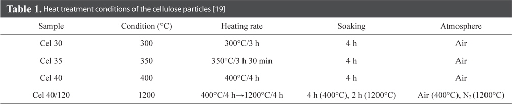
Heat treatment conditions of the cellulose particles [19]
[Table 2.] Compositions of the PAN-DMSO solution containing the heat-treated cellulose particles
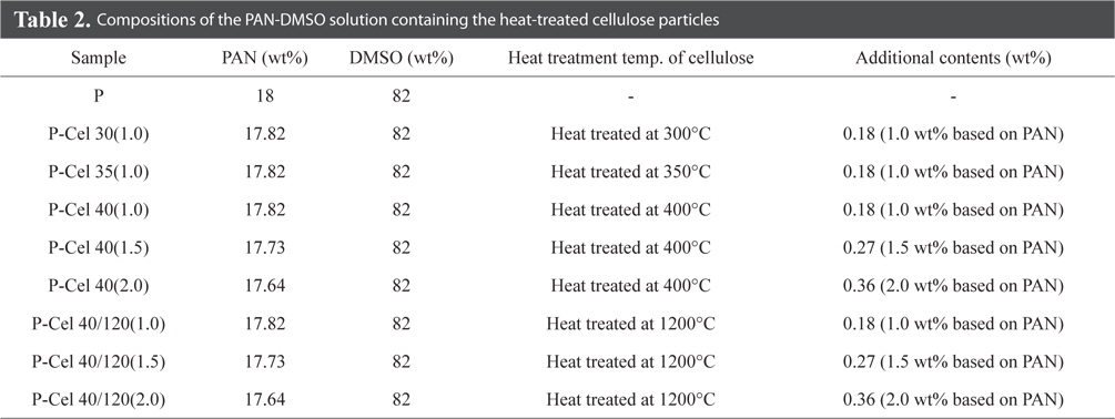
Compositions of the PAN-DMSO solution containing the heat-treated cellulose particles
To prevent excessive shrinkage of the PAN fibers containing carbonized cellulose particles, stabilization was done by applying a given tension at 290℃. At this time, side face and cross sectional shapes of the fibers were observed by field emission scanning electron microscopy (FE-SEM, XL30, Philips), and crystal structure characteristics were observed with X-ray diffraction (XRD, D8 Discovery, Brukers).
Composite carbon fibers were prepared by ambient cooling after carbonization of the stabilized composite fibers in a nitrogen atmosphere at a rate of 5℃/min. up to 1200℃. Side face and cross sectional shapes were observed by SEM, and the crystal structure of the spun, stabilized, and carbonized fibers were observed with XRD. Additionally, the effects of the heat treatment temperatures of the cellulose particles and the changes in the amounts of cellulose particles added to the carbon fibers on the mechanical characteristics of the composite carbon fibers were investigated. Tensile strengths and moduli of fibers were measured with a universal tensile tester (UTM, Instron 4467, Instron Co.). Thermal conductivities of the composite carbon fibers were measured with a thermal conductivity measuring instrument (LFA447, NETZSCH Co.). Thermal diffusivity (α) was obtained with the laser flash method, and thermal conductivity (λ) of the specimens was calculated with the density (ρ) obtained from Archimedes principle and the specific heat (Cp) measured with the differential scanning calorimetry. Thermal conductivity was calculated with formula below.
λ(T) = α(T)ρ(T)Cp(T)
Specimens of the composite carbon fibers were made into a disk shape with a diameter of 12.5 mm and a thickness of 1.5 mm and arranged so that the disk was perpendicular to the transmitted laser radiation. Additionally, by measuring and comparing pure thermoplastic resin specimens prepared in the same manner, the practical thermal conductivity of the composite carbon fibers was calculated. According to the method presented in ASTM E1461 [20], measurements were made by raising temperatures from room temperature to 150℃.
3.1. Stabilization characteristics
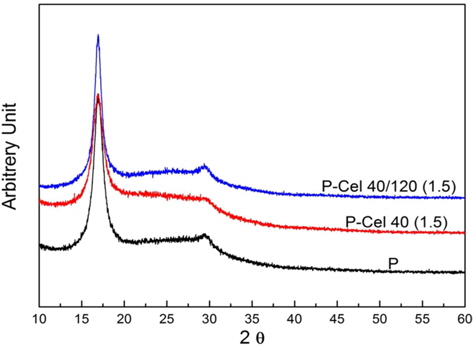
Fig. 1 shows the crystal structures of the pure PAN fibers and the PAN fibers with cellulose particles fabricated with wet spinning for spun fibers under typical conditions. There was no difference in the crystal structure between the samples among the P, P-Cel 40 (1.5), and P-Cel 40/120 (1.5) when only the PAN crystal structure was observed. This result appears to be attributed to the weak crystallinity and low contents of the cellulose particles.
Fig. 2 shows the results for the crystal structure after stabilizing the same specimens in Fig. 1. The stabilization process for PAN fibers was first described by Xue et al. [21] as the extinction of the PAN structure resulting from cyclization and dehydrogenation from the oxidation reaction to establish thermal stability. The extinction of the crystallinity for the (010) and (300) planes of PAN was observed as a result of the destruction of the structure by decomposition or oxidation of O2 or OH, etc. in the stabilization process of the PAN fibers. Our results are in agreement with the assertions by Xue et al. [21].
Whereas the weak crystalline characteristics of PAN exist in the case of the pure stabilized fibers, complete extinction of the PAN structure under the same stabilization conditions for the composite stabilized fibers containing the heat-treated cellulose particles could suggest that the carbonized cellulose particles present within the matrix act as a seed to accelerate the stabilization process of PAN. This could be interpreted from a thermodynamic viewpoint to indicate that the stabilization process occurs easily because of an increase in the free energies of the system as a result of the mixing.
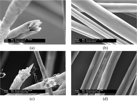
Fig. 3 shows the shapes of the spun fibers, in which Fig. 3a and b show the shape of pure PAN fibers, while Fig. 3c and d show the shape of the PAN fibers containing the carbonized cellulose particles. Although the fluid properties of the solution due to the cellulose particles changed in the case of the mixed PAN solution, the surfaces or internal structures of the fibers extending from the confinement appear to be different because the spinning conditions were applied in the same manner. Fig. 3a and c show the fiber cross sections, in which the observation of internal structures through brittle fractures in the surface was difficult due to the high toughness of the material even though they fractured under liquid nitrogen condition. After the coagulation bath following spinning from the broken form, hard cellulose particles embedded in the PAN fibers could be observed to split the fibers in the axial direction for subdivision in the elongation process. The side face shape of the fibers enabled easy mutual comparisons. The pure PAN (Fig. 3b) exhibited smoother surface characteristics than the PAN containing cellulose particles (Fig. 3d). Particularly, in the case of Fig. 3d, surface defects due to cellulose particles could be observed.
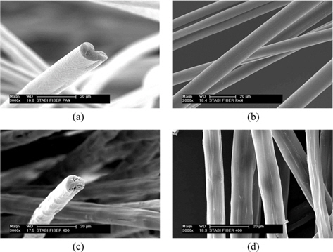
Fiber shapes after stabilization are shown in Fig. 4. While the fiber shapes were not greatly changed, observation of fractures on the surface was made easy due to bond weakening as a result of the changes in the PAN structure such as chain destruction during the stabilization process. In the case of Fig. 4a for P-ST as a pure PAN fiber sample, it was relatively smooth, while pores were present and the surface was rough in the case of (c) for P-Cel 40(1.5)-ST with addition of cellulose. Here, ‘-ST’ means ‘stabilization.’ The low structural soundness of the shapes seems to come from the irregularities in the flow of the spinning solution.
3.2. Carbonization characteristics
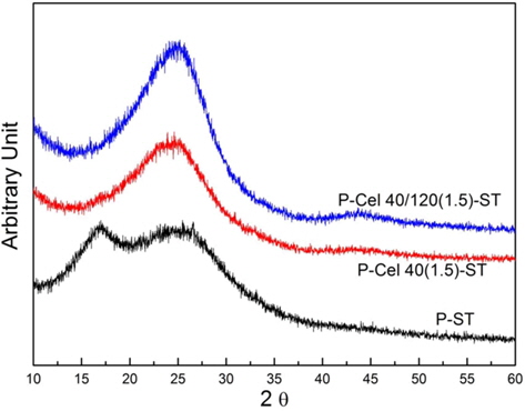
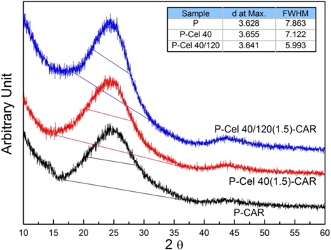
Fig. 5 shows the analysis results of the crystal structures of the samples carbonized by raising the temperatures of the stabilized fibers at a rate of 5℃/min up to 1200℃. Although there were no clear differences between the pure carbon fibers and the composite carbon fibers, the rate of carbonization for the composite fibers containing the cellulose particles carbonized at 400℃/1200℃ was somewhat higher based on the crystal structure analysis. Namely, although the d values showing the distance between the crystal planes of the carbon atoms were similar, the full width half maximum values showing the extent of the crystallization of the composite carbon fibers containing the cellulose particles carbonized at 400℃/1200℃ were the smallest suggesting that the composite fibers containing the cellulose particles have the best crystallinity. As mentioned in the stabilization process, this can be explained by the fact that cellulose particles act as seeds facilitating reactions. It shows that the carbonized fine cellulose particles have the role of accelerating the carbonization of neighboring fiber structures.
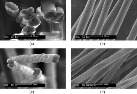
Fig. 6 shows the shapes of the various carbon fibers. The cross section and surface shapes are similar to the stabilized fiber shown in Fig. 4, and in Fig. 6c for the composite carbon fibers containing the carbonized cellulose particles, it was observed to have more internal defects than in Fig. 6a for the pure carbon fiber, also accompanied by greater surface roughness. Consequently, these are considered to be phenomena related to the structure of the stabilized fibers containing cellulose particles.
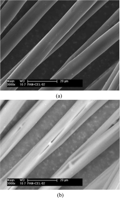
Fig. 7 shows the SEM images for the composite carbon fibers containing cellulose particles, which were acquired with a different beam source. Although not revealed in Fig. 7a as a secondary electron image, the internal existence of carbonized cellulose particles less than a few micrometers were confirmed based on Fig. 7b, a back-scattered electron image. In addition, the existence of longitudinal pores along the fiber axis direction were confirmed which were produced during the tensile process in the structures around the cellulose particles after spinning.
3.3. Mechanical characteristics
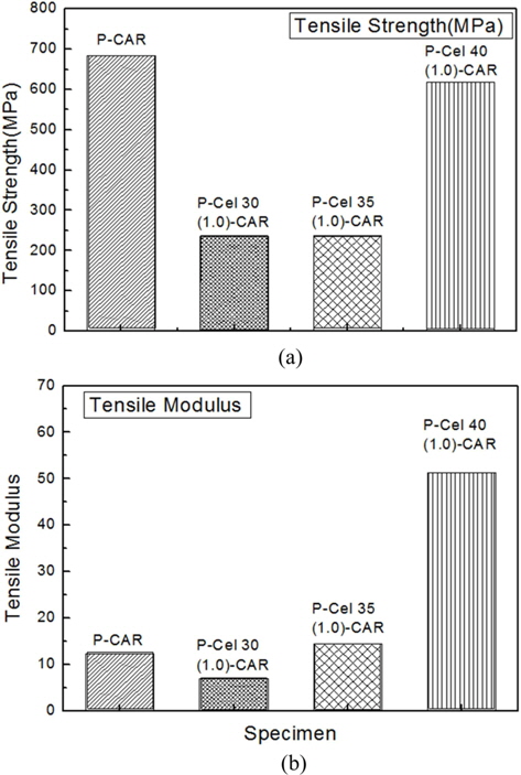
To consider the mechanical characteristics of the composite carbon fibers as a function of the heat treatment temperatures of the carbonized cellulose particles, tensile strengths and tensile moduli were measured for the composite carbon fibers prepared by mixing carbonized cellulose particles under various heat treatment conditions. Table 3 and Fig. 8 show the results for the mechanical properties of the composite carbon fibers prepared with the same cellulose contents while only changing the carbonization conditions for the cellulose particles. ‘-CAR’ means ‘carbonization.’
[Table 3.] Mechanical properties of the carbon fibers for varying heat treatment conditions
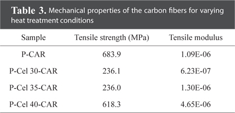
Mechanical properties of the carbon fibers for varying heat treatment conditions
Based on the tensile strength results shown in Fig. 8, the tensile strength of P-Cel 40(1.0)-CAR as composite carbon fibers with cellulose particles carbonized at 400℃ had a value corresponding to 90.4% of P-CAR as the pure carbon fiber. These values show a much higher strength than those for the other composite carbon fibers. In comparison with the pure carbon fibers, a reduction in the tensile strength when the carbonized cellulose particles were added was due to the fact that the carbonized cellulose particles acted as defects inside the carbon fibers, as somewhat expected.
Tensile strengths of the carbonized cellulose particles heat-treated at 300℃ where thermal decomposition of the cellulose started and at 350℃ where thermal decomposition was actively in progress were relatively lower than those of the composite carbon fibers with the addition of carbonized cellulose particles heat-treated at 400℃. This is attributed to the fact that defects were produced inside due to the thermal decomposition products of the cellulose particles which did not finish decomposing during the carbonization processes. From a previous study [19], the completion of thermal decomposition of cellulose particles at 400℃ was confirmed, through which the decreased rate of reduction of the tensile strength could be attributed to a marked decrease in defect production caused by un-decomposed materials in the case of composite carbon fibers with the carbonized cellulose particles heat treated at 400℃.
Fig. 8 and Table 4 show the tensile moduli for the composite carbon fibers as a function of the heat treatment temperatures of the cellulose particles. The modulus of the composite carbon fibers containing the cellulose particles heat treated at 400℃ was increased 4.3 times compared with that of the pure carbon fibers. There was a reduction of 0.57 times and an increase of 1.2 times in the case of adding cellulose particles heat treated at 300℃ and 350℃, respectively, showing a relatively great increase for the former case. Such results are caused by the hindrance of deformation due to the tensile forces in the axial direction because the hard carbonized cellulose particles are irregularly distributed inside the carbon fibers on a whole, and these are embedded in a wedge form shown in Fig. 7b. Because such an increase in the tensile modulus improves the dimensional stability of the composites, shape stability is observed in the composite materials.
[Table 4.] Mechanical properties of the carbon fibers for varying cellulose particle contents
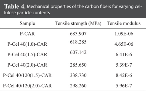
Mechanical properties of the carbon fibers for varying cellulose particle contents
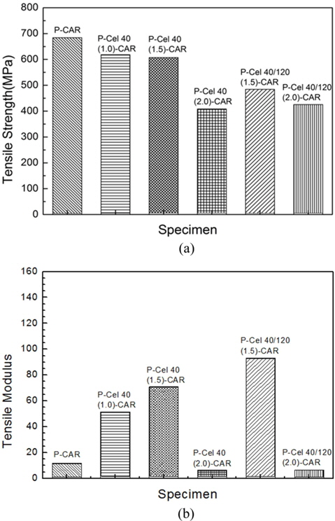
To consider the mechanical characteristics of the composite carbon fibers as a function of the heat-treated cellulose particle contents, composite carbon fibers with addition of 400℃ carbonized cellulose particles at 1.0, 1.5 and 2.0 wt% as well as composite carbon fibers with addition of 400℃/1200℃ carbonized cellulose particles at 1.5 and 2.0 wt% were prepared, and the measurement results of their tensile strengths and tensile moduli are given in Table 4 and Fig. 9.
Tensile strengths decreased as the carbonized cellulose particle content decreased, in the case of the samples with the 400℃ and 1200℃ carbonized cellulose particles at 1.5 and 2.0 wt%. Such results are due to the carbonized cellulose particles acting as impurities in carbon fibers to form defects in the structures, and is attributed to a decrease in strength with an increase in the amount of impurity.
The tensile moduli of the composite carbon fibers with the carbonized cellulose particles could be higher than those of pure carbon fibers, because as the carbonized cellulose particle contents decreased, the values for the tensile moduli became higher. Based on such results, it can be predicted that an optimum amount of cellulose particles exists to maximize the tensile modulus of the carbon fibers.
3.4. Thermal conduction characteristics
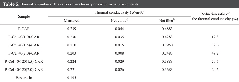
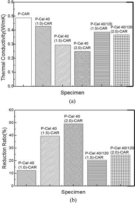
Because accurate measurements of a single fiber are very difficult, the thermal conductivity of the composite materials was measured using 15 wt% composite carbon fibers in a thermosetting resin as a reinforcing material for the composite in the case of the carbon fibers. The results are compared in Table 5 and Fig. 10.
[Table 5.] Thermal properties of the carbon fibers for varying cellulose particle contents

Thermal properties of the carbon fibers for varying cellulose particle contents
Compared with 0.195 W/m·K for the thermal conductivity of the thermosetting resin, the thermal conductivity of the specimens filled with carbon fibers increased to 0.239 W/m·K. This is due to the fact that the thermal conductivity of the carbon fibers has higher values compared with that of the polymer resin as the parent material. Thermal conductivities of the composite carbon fibers containing the carbonized cellulose particles were less than that of the pure carbon fibers, while the thermal conductivities of the samples decreased as the carbonized cellulose particle contents increased. In the case of the P-Cel 40(2.0)-CAR specimens, the thermal conductivity of the fiber had the lowest value of 0.2483 W/m·K. Thermal conductivity of P-Cel 40/120-Car was higher than that of the P-Cel 40(2.0)-CAR.
The reduction phenomenon of the thermal conductivities resulting from the addition of the cellulose particles could be explained as follows. First, as confirmed in the microstructure results of the composite carbon fibers, the effect of the fine internal pores produced by the added cellulose particles could reduce the thermal conductivity. The second explanation is related to the cellulose crystal structure. The added cellulose particles are present between the hexagonal network planes oriented in the axial direction of carbon fibers so as to increase irregularities. Consequently, the movement of π-electrons in the axis direction of the fibers is hindered by the cellulose particles.
As a result, the lowest thermal conductivity in the present results was P-Cel 40(2.0)-CAR. However, considering the tensile strength, P-Cel 40(1.5)-CAR has the most desirable properties.
To conduct a study on composite carbon fibers applicable to areas requiring thermal insulation and shape stability by lowering the thermal conductivities of carbon fibers while increasing the tensile modulus, composite carbon fibers with the addition of carbonized cellulose particles were prepared, and their characteristics were investigated. The following conclusions were obtained from the results.
1) Although the crystal structure of the composite carbon fibers with the addition of carbonized cellulose particles was the same as that of the carbon fibers, the images observed in SEM appeared to be very different. This phenomenon was interpreted as being caused by a difference in the liquidity between the two phases contained in the spinning solution.
2) Tensile strength of the composite carbon fibers containing the carbonized cellulose particles decreased compared to that of the pure carbon fibers. This is due to the fact that the carbonized cellulose particles acted as an impurity inducing defects. According to the strength measurements of the composite carbon fibers varying the heat treatment temperatures and the cellulose particle contents, the tensile strength for the case with the addition of 1.0 wt% cellulose particles carbonized at 400℃ was about 90% of that for the carbon fibers, with tensile modulus being increased up to 4 times compared with the pure carbon fibers. This is interpreted as an effect of the cellulose particles which exist in a wedge form within the composite carbon fibers.
3) According to the results for the change in thermal conductivity of the composite carbon fibers based on the cellulose particle contents, a reduction effect of 49.2% compared with the pure carbon fibers was observed in the case of adding 2.0wt% cellulose particles carbonized at 400℃.
4) The optimum condition capable of maximizing the reduction of thermal conductivity while minimizing the reduction of tensile strength under the present experimental conditions was the composite carbon fibers containing 1.5 wt% cellulose particles carbonized at 400℃. While an increase in the initial tensile modulus to 7.7 times that of the pure carbon fibers and a decrease in thermal conductivity by 39.6% could be obtained, the tensile strength decreased by 11.0%.
The results show that it is possible to manufacture composite carbon fibers with low thermal conductivity. The thermal conductivities were reduced by combining heat-treated cellulose particles with carbon fibers while the tensile strength loss was minimized, and the tensile modulus increased.

![Heat treatment conditions of the cellulose particles [19]](http://oak.go.kr/repository/journal/15754/HGTSB6_2015_v16n3_203_t001.jpg)