Graphite can be classified into natural graphite from mines and artificial graphite. Due to its outstanding properties such as light weight, thermal resistance, electrical conductivity, thermal conductivity, chemical stability, and high-temperature strength, artificial graphite is used across various industries in powder form and bulk form. Artificial graphite of powder form is usually used as anode materials for secondary cells, while artificial graphite of bulk form is used in steelmaking electrode bars, nuclear reactor moderators, silicon ingots for semiconductors, and manufacturing equipment. This study defines artificial graphite as bulk graphite, and provides an overview of bulk graphite manufacturing, including isotropic and anisotropic materials, molding methods, and heat treatment.
Graphite was used in crucibles since the 15th century. In 1550, it began to be used in pencils, and Abraham Gottlob Werner (1750-1817) coined the term “graphein,” from “to write” in Greek [1-4]. The development of graphite was closely related to that of electricity. In the early 1800s, carbon electrodes were first used in a study on electric arc by Humphry Davy (1778-1829). In roughly 1870, the manufacturing of artificial carbon improved with increased market demand for electric arc light carbon (CARRÉ, BRUSH, Siemens). After Acheson patented an electric furnace capable of withstanding temperatures up to 3000℃ (1896), new processes involving carbon and graphite electrodes became available at the start of the 20th century [1].
1.2. Structure and characteristics
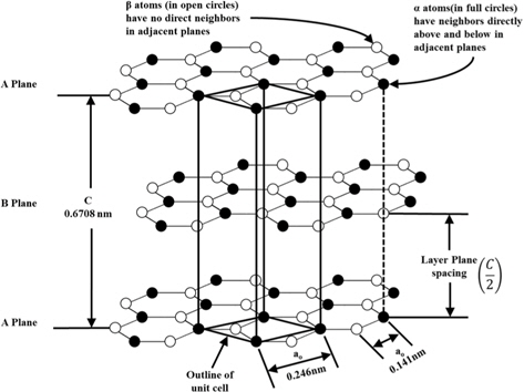
Fig. 1[5] shows the crystal lattice of a hexagonal graphite with an -ABAB- stacking sequence [6-8]. Graphite consists of rings of six carbon atoms, and the sp2 carbon atom of the hexagonal basal plane has three σ electrons in the same plane and one π electron in the perpendicular direction, giving it a bond strength of 524 kJ/mol. Weak van der Waal forces (7 kJ/mol) exist between basal planes [9-16]. The rhombohedral structure having an -ABCABC- stacking sequence accounts for up to 30% of the structure in natural graphite, but is converted to a hexagonal structure at temperatures higher than 1300℃ due to the former’s lower stability compared to hexagonal graphite [1,13-18].
Graphite has low thermal expansion, outstanding thermal shock resistance under rapid changes in temperature graphite, and good chemical stability [19]. Other advantages include electrical and thermal conductivity, dewetting, and self-lubrication. It is widely used in nuclear reactors because of its high-temperature strength and high tolerance to neutron irradiation compared to other metals and ceramics [20,21].
Graphite is oxidized when used in oxygen-containing gas, and begins to react with oxygen at around 420℃-460℃, releasing carbon monoxide and carbon dioxide during oxidation. Known for its thermal stability, graphite remains stable under nitrogen, chlorine, and argon atmospheres [19]. Table 1 shows the reactivity of graphite under various atmospheres and with different gases.
[Table 1.] The reactivity of graphite under various atmospheres and with different gases [19]
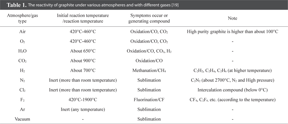
The reactivity of graphite under various atmospheres and with different gases [19]
Artificial graphite refers to specific materials given high-temperature heat treatment to attain the crystal structure of graphite. It can be classified into powder form and bulk form. Artificial graphite of powder form is usually used as anode materials of secondary cells [22], while artificial graphite of bulk form is used in steelmaking electrode bars and crucibles.
Artificial graphite of bulk form is made by adding a binder to a carbon-based filler, i.e. coke and tar, followed by heat treatment [23]. In general, heat treatment is performed at 2500℃-3000℃ but higher temperature is required to achieve a structure closer to that of natural graphite [24-26]. The first commercial artificial graphite of bulk form was synthesized by Edward Goodrich Acheson. After experimenting with silicon carbide, he found that the silicon component evaporates at 4150℃, leaving behind carbon in the form of graphite. Acheson patented this graphite manufacturing method in 1896 and began commercial production in the following year [2].
Graphite is used in steelmaking electrode bars (high electrical conductivity), silicon ingot manufacturing equipment materials, refractories (heat resistance, dewetting and high-temperature strength), bearings, special machine parts (self-lubrication), cell divider plates, and mechanical seals (air-tightness and fire resistance) [20,21,27,28]. This paper defines artificial graphite in bulk form as bulk graphite, and provides an overview of its classification, materials, molding methods, and heat treatment methods.
3.1. Classification of bulk graphite
Graphite has anisotropic crystals due to the planar structure built on the hexagonal basal plane [29]. As such, the physical properties of bulk graphite vary with the method or degree of orientation of crystals. During bulk graphite manufacturing, the material is classified into anisotropic or isotropic depending on the orientation of particles.
3.1.1. Isotropic bulk graphite
Isotropic materials are materials having the same properties regardless of orientation in ceramics or materials engineering. Isotropic bulk graphite is obtained by applying cold isostatic pressing (CIP) to carbon-based materials, and the anisotropic ratio is about 0.98 to 1.10 [30-33]. They are widely used in electrodes for electric discharging, jigs, crucibles, heating elements, continuous casting dice, and materials for nuclear reactors due to their high strength, air-tightness, chemical resistance, and machinability [20,21,27,28].
3.1.2. Anisotropic bulk graphite
Anisotropic materials are materials having different physical and chemical properties depending on the orientation in ceramics or materials engineering. This is because the materials are arranged in a way that maintains the macroscopic orientation [34]. Anisotropic bulk graphite is obtained by applying extrusion and compression molding to anisotropic carbon-based materials. Different physical properties are observed in the direction of extrusion and compression molding, and in the corresponding perpendicular direction. The anisotropic ratio is about 1.73 to 25 [5,33]. Anisotropic bulk graphite is used in products requiring high electrical and thermal conductivity, such as steelmaking electrode bars and aluminum smelting electrodes [20,21,27,28]. Table 2 shows the coefficient of thermal expansion (CTE) and CTE ratio (anisotropic ratio) of nuclear graphite, electrode graphite and pyrolytic graphite.
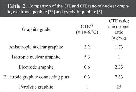
Comparison of the CTE and CTE ratio of nuclear graphite, electrode graphite [33] and pyrolytic graphite [5]
4. Manufacturing Process of Bulk Graphite
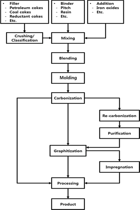
The general manufacturing process of bulk graphite is shown in Fig. 2, and a schematic diagram is presented in Fig. 3[35]. The particle size and the mixing ratio are determined based on usage of the filler and binder, and mixing is performed at a temperature higher than the softening point of the binder. The filler is usually coke, or occasionally natural graphite, carbon black, and graphite scraps. The binder is usually petroleum pitch and coal tar pitch with high carbonization yields, or thermosetting resins such as phenol and epoxy.
The mixture is molded by extrusion, compression molding or CIP or rubber pressing. The molded bulk undergoes heat treatment at 700℃-1200℃(carbonization). Impregnation and re-carbonization are repeated to fill the pores generated due to impurities in the filler and volatility of the binder. This is followed by graphitization and purification at high temperatures in a range of 2500℃-3000℃ [24-26,36,37].
Carbonization removes foreign atoms and hydrogen substituents to transform organic precursors into carbon polymers. These polymers are composed of polycyclic aromatic carbons. If heat treatment is continued, this carbon assumes a structure similar to that of graphite.
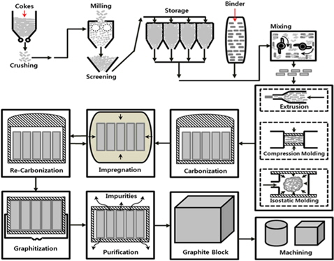
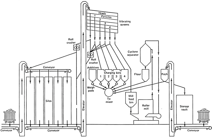
The characteristics of bulk graphite differ according to the ease of transformation and extent of graphitization during the chemical and physical process, and bulk graphite materials are usually obtained from fuel and coal [38]. The selection of adequate materials is an important first step in bulk graphite manufacturing since it determines its size, characteristics, and cost [39]. The factors to be considered include coke recovery, particle size, carbonization of the binder, particle structure of carbon black, impurities, and particle size of natural graphite. For instance, for electrodes more emphasis is placed on low cost than properties, while nuclear applications require smaller amounts of impurities and superior characteristics. Materials can be largely divided into four types: filler, binder, impregnants, and additives [5,40]. The materials processing technology is shown in Fig. 4.
4.1.1. Filler materials
Filler materials used in bulk graphite manufacturing can be classified into coke (petroleum coke, pitch coke, metallurgical coke), anthracite, carbon black, natural graphite, and artificial graphite [1]. Adequate filler materials should be selected depending on the usage and physical properties of the final graphite product. These filler materials can be divided according to particle form and microstructural orientation. Since physical, electrical, and chemical properties differ according to orientation, the classification of filler materials by orientation is important in the design of bulk graphite properties.
1) Isotropic filler materials
Isotropic filler materials have no anisotropic particles, but must be microscopically isotropic. The types of coke most commonly used in bulk graphite manufacturing are petroleum coke, The microstructures of pitch coke and metallurgical coke and isotropic coke are mostly mosaic and heterogeneous.
Petroleum coke (regular coke), the by-product of producing ethylene from fractional distillation of crude oil, is the most common isotropic filler material used in bulk graphite manufacturing [41]. Pitch coke is known to have better hardness and strength compared to petroleum coke as it involves heat treatment of coal tar pitch [42]. Metallurgical coke and anthracite are used as refractory lining of steelmaking blast furnaces or aluminum steelmaking cathodes. In addition, metallurgical coke is used as packing to protect products that undergo heat treatment in the graphitization furnace [1].
Carbon black, occurring in the form of spherical particles of tens of nanometers, is used as an additive to enhance the density, electrical resistance, and polishing characteristics of bulk graphite products [43].
2) Anisotropic filler materials
Anisotropic filler materials have particles in needle-like or plate-like forms and are characterized by their microstructural anisotropy. These anisotropic filler materials can be largely classified into needle coke and flake graphite (natural).
Needle coke refers to coke that becomes needle-like and breaks easily when ground. In the 1940s, petroleum coke manufactured in the United States was found to be acicular and highly crystalline, and also came to be known as premium coke. The anisotropic region in needle coke represents the flow domain. Needle coke has a condensed hexagonal network in the flow direction, and is used as a material of anisotropic bulk graphite [1,44]. The physical properties differ greatly depending on the axial direction due to its low coefficient of expansion and high anisotropy [45,46].
Microscopic observations show that needle coke has a fibrous texture and a well-developed hexagonal network in the flow direction, making it a suitable material for graphitization. The manufacturing of needle coke was developed in the United States in the 1950s based on the selection of aromatic materials and optimization of delayed coking conditions.
Flake graphite, with a carbon content greater than 99%, is a plate-like and highly crystalline graphite. Crystalline graphite exists in mineral form and is called natural graphite. Among the various types of graphite known today, the most outstanding is Sri Lankan natural graphite with a purity close to 100% [47,48]. Flake graphite is characterized by its high anisotropy in physical, electrical, and mechanical properties. As such, natural graphite is widely used in solid lubricants, crucibles, refractories, pencils, and electrode materials for batteries [20,21,27,28].
4.1.2. Binders
Common binders include thermosetting resins and tar pitch. Tar pitch is a by-product of steel production, and is obtained from the distillation or heat treatment of tar. The composition of tar pitch is relatively complex, and varies according to the amount of tar distillation. Factors that affect the graphitization characteristics and quality of pitch are as follows: 1) softening point and 2) the amount of quinolone (C9H7N). Tar pitch and thermosetting resins are used in products requiring varying levels of strength [49].
1) Pitch
Pitch is the residue obtained during thermal decomposition of organic matter or tar distillation. It is derived from heat treatment and polymerization of liquid tar produced during dry distillation of petroleum or coal, oil distillate from oil sand and oil cells, and residue of thermal decomposition. Since pitch exists in a solid form at room temperature and is a complex mixture of aromatic or heterocyclic hydrocarbons, its molecular weight ranges from 100 to thousands, with the average falling between 300-1000 [50].
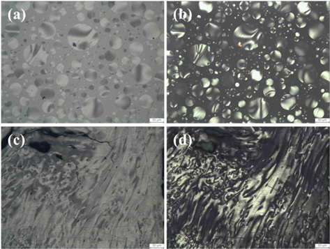
Pitch as binder offers the advantages of low softening point, low melt viscosity, high carbon yield, and ease of graphitization. During heat treatment, pitch attains low viscosity through the emission of oxidized functional groups, sulfur, and nitrogen. At around 400℃-450℃, pitch forms anisotropic liquid crystals, and this is known as the mesophase. Fig. 5 shows the microscopic image of pitch after heat treatment at 400℃ and 500℃. The mesophase nucleus is observed in the pitch following heat treatment at 400℃, and the mesophase combines into a flow structure at 500℃. The transition of the mesophase during heat treatment consists of the following: 1) nucleus formation, 2) growth of the nucleus, 3) combination of spherical mesophase, and 4) transition into bulk mesophase [51-57]. Pitch is carbonized after molding the mesophase through heat treatment, and the lamella layer formed at temperatures higher than 2300℃ leads to the crystalline structure of graphite [58]. Table 3 compares the physical properties between petroleum pitch and coal tar pitch.
[Table 3.] Properties of petroleum impregnating and coal-tar binder pitches [38]
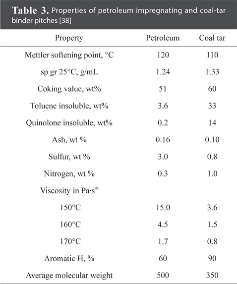
Properties of petroleum impregnating and coal-tar binder pitches [38]
2) Phenolic
Phenolic ((C15O2H20)n) is a category of polymers obtained from polymerization between phenols and formaldehydes. It has a nongraphitizable carbon structure, and assumes a three-dimensional networked structure with the growth of La crystals after polycondensation, softening, carbonization, and heat treatment.
Marinkovic and Yamashita studied the phenol carbonization process and reported that water is released from 180℃, followed by carbon monoxide, carbon dioxide, methane, and hydrogen after 400℃. At around 500℃, gases are most actively decomposed and volatilized [59-61]. Most of these reactions end before the temperature reaches 700℃, but small traces are emitted even after 700℃ in the case of very small hydrogens.
Phenolic binders show high specific strength, specific gravity, thermal resistance, and carbonization yield. They are widely used in parts requiring surface strength since heat and pressure can be applied to transform them into heat-resistant materials with high mechanical strength [62-63]. This study does not cover processes involving phenolic binder.
4.1.3. Additives
Other than filler and binder, additives are added during bulk graphite manufacturing. While additives are introduced only in traces, they play a key role in determining the quality of bulk graphite products. Petroleum oil, wax, extrusion oil including fatty acids and esters, and lubricants are added to improve the extrusion speed and structure of extrusion molded products [64].
Chemical suppressants are used to reduce defects arising from sulfur content. Iron oxide is added to prevent rapid expansion of coke due to sulfur volatized at 1600℃-2400℃. Fe2O3 or other iron compounds prevent expansion by reducing gas pressure and molding a more stable iron oxide [38]. Other compounds that can be used are sodium hydroxide, nickel, cobalt, and vanadium [38].
Particle size controls the density and characteristics of bulk graphite. The particle size of filler and binder are milled to 1 µm-1.25 cm depending on usage. Table 4 shows the particle size and characteristics for various grades [5].
[Table 4.] Particle sizes and characteristics of graphite grades [5]
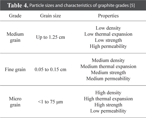
Particle sizes and characteristics of graphite grades [5]
Filler that have been milled according to usage are mixed in adequate proportions to be coated with binder. This is usually performed at temperatures (160℃-170℃, max. 315℃) higher than the softening point of binders when mixed at low temperatures (lower than the binder softening point), volatile solvents such as acetone and alcohol are added to binders to accelerate dispersion. The characteristics of bulk graphite are influenced by 1) mixture viscosity, 2) flow, and 3) fluid interactions between fillers [65].
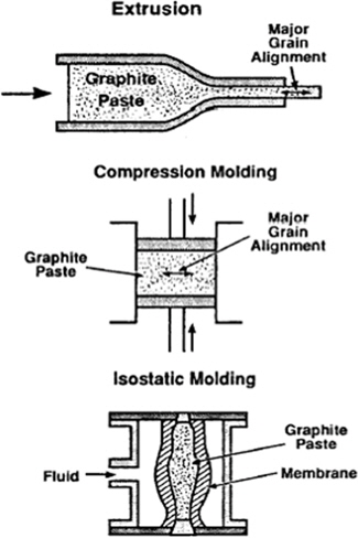
One of the goals of molding is to compress mixtures to have high densities. In most fields of application, the foremost goal of bulk graphite manufacturing is to maximize density. The aim of molding is to manufacture products in shapes and sizes that have other uses than the intended purpose. This helps to reduce by-products and minimizes machining costs. The molding of mixtures affects the porosity of bulk graphite and the orientation of materials, factors that are related to the characteristics of bulk graphite [66,67]. The three technologies of molding are extrusion, compression molding (uniaxial loading), and CIP. A schematic diagram of these three techniques is given in Fig. 6. Different molding techniques are selected according to usage. The properties of each molding technique can be found in Table 5.
[Table 5.] Characteristics of molding techniques [5]
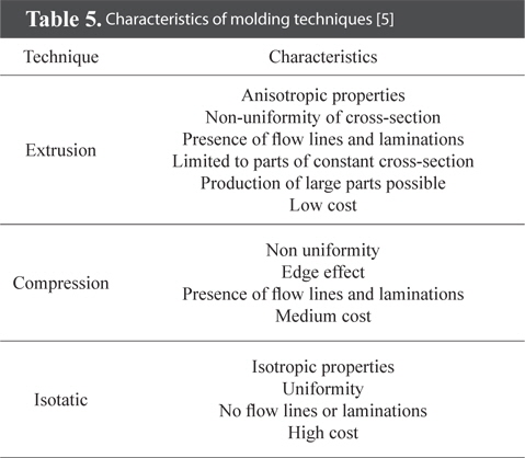
Characteristics of molding techniques [5]
4.3.1. Isotropic molding (CIP)
CIP applies constant pressure in all directions using an elastic material such as rubber or silicon in the fluid chamber. Bulk graphite produced by CIP is isotropic and has hardly any defects [1]. The pressure tank of CIP has a radius of 1 m and a height of 2.5 m. The maximum pressure is 200 MPa [68].
Compared to other molding methods, the molded bulk graphite is weakly anisotropic even when molded into natural graphite or anisomeric powder such as needle coke [1]. However, this method involves higher costs than extrusion or compression molding.
4.3.2. Anisotropic molding
1) Extrusion molding
Extrusion molding is applied to electrodes and other products requiring a consistent cross section. Mixtures cooled to approximately 125℃ are extruded through a steel die, and the binder pitch is cooled and solidified before any deformation occurs. The extruded mixture is referred to as the green body (green shape). The extrusion pressure is 7 MPa (100 psi). Fillers are oriented in the extrusion direction, and the manufactured bulk graphite has anisotropic properties [5]. The extent of anisotropy can be controlled by the mixing proportion and the shape of the mixture. Flow lines and stacking faults are found in the center of extruded materials, lowering the quality of this area compared to the edges [69,70].
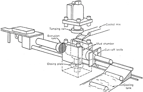
Fig. 7 is a schematic diagram of tilting extrusion press, a method of extrusion molding. The cooled mixture is supplied into the mud chamber from a perpendicular position. A tamping ram is employed to extrude the mixture from the mud chamber. While the closing plate applies high-pressure ramming, and a vacuum pump may be used to protect the mixture or suck out air. The ground mixture is extruded to the die under a pressure of 3-15 MPa through the extrusion ram. A scaffold-like blade slices the extruded material into fixed lengths at the die exit. The cylindrical extruded materials roll off to the tank in water, and this is intended to rapidly cool them to avoid twisting. The temperature of the cooling water must be adjusted to prevent cracks that may occur from rapid cooling. This extrusion process leads to anisotropic properties in bulk graphite [68].
Anisotropic coke particles are aligned in a direction horizontal to the extrusion direction. For this reason, the key elements that determine green body characteristics are coke type, particle size, and the ratio of the radius of the die to mud chamber. When the radius ratio of the mud chamber and die increases, the conductivity increases while the resistance and the expansion coefficient decrease. When the diameter is reduced from 600 to 400 mm, anisotropy is enhanced even if other conditions remain the same [68].
Depending on the particle orientation, the extruded bulk graphite has an increase in strength, elastic coefficient, and thermal conductivity but a decrease in electrical resistance and expansion coefficient [68]. The extruded materials of carbon electrodes are extruded at a radius of 800-1400 mm [71], while the extruded materials of graphitized electrodes are extruded at 350-800 mm [72].
2) Compression molding
Compression molding is applied in the molding of small-sized bulk graphite and aluminum smelting electrodes. A tungsten carbide die is used for molding at 28-280 MPa (4000-40000 psi). Complex materials can be produced based on the extrusion molding technique. However, the manufactured bulk graphite does not have uniform density due to friction with die walls and the edge of the die [5]. The green body is more easily transformed compared to extrusion molding because of weak flow during compression molding [73].
Compression molding occurs as single or double deck molding, depending on the number of press plates. In single deck molding, the depth is smaller than the cross section. As the depth increases, the molding pressure is reduced due to frictional loss along the mold walls with increased distance to punch. To increase the depth of the green body, double deck compression molding must be used, which applies the same pressure to the top and bottom.
During compression of the mixture, anisometric particles are oriented in a direction perpendicular to the applied pressure. The molded bulk graphite has a strength, stiffness, and conductivity higher in a direction perpendicular to the load, and an expansion coefficient higher in the direction of the load [68].
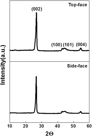
Bulk graphite manufactured from compression molding has various applications such as brushes, seals, and bearings [1]. When compression molding is performed using isotropic fillers, isotropic bulk graphite is produced. Fig. 8 shows the X-ray diffraction data of the face perpendicular to the compression direction (top face) and the face parallel to the compression direction (side face). The degree of alignment was derived, and the calculated anisotropy ratio of 1.13, as shown in Table 6, demonstrates the outstanding isotropic properties of bulk graphite [30].
[Table 6.] Degree of alignment and anisotropy ratio from X-ray diffraction [30]
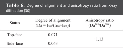
Degree of alignment and anisotropy ratio from X-ray diffraction [30]
Carbonization involves heating of bulk graphite in an inactive or reducing atmosphere, and this takes several days or weeks depending on the size and shape. Complex dehydrogenation and copolymerization reactions occur simultaneously during this process [5]. Organic materials are decomposed into carbon, while volatile components are dispersed and released into the atmosphere. The dispersion of volatile components is an important stage, and must be carried out slowly to avoid breaking of carbon chains. As a result, carbonization is slow and timeconsuming.
For instance, temperature must be slowly increased since the volatile components of the binder cause cracks in bulk graphite up to 600℃. At this point, bulk graphite shrinks and hardens, decreasing in size by approximately 6%.
Carbonization is performed at a temperature of 760℃-980℃ (or up to 1200℃ in special cases) [5].
Due to the long time involved in cooling after heat treatment, the carbonization cycle from the furnace to exposure takes at least one month. The furnace is known as the lead hammer furnace, and exists in the form of a continuous, independent, or shuttle furnace [74].
Impregnation refers to the process of removing residual air, which is a cause of leakage and subsequent defects, from pores and adding an impregnant to fill the pores.
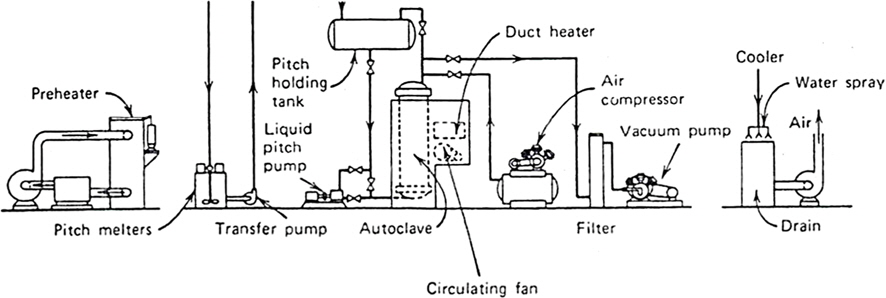
The first stage of impregnation is to apply a pressure lower than 3.5 KPa (26 mmHg) for an hour or more depending on the infiltration capability or size of bulk graphite. If a vacuum state is not reached, the air in open pores interferes with the introduction of the impregnant. The heated pitch follows the flow of gravity in the autoclave from the holding tank until filling is complete. This system is subject to a pressure of 700-1500 KPa (7-15 atm) for several hours to reduce the number of impregnation. Re-carbonization is necessary before graphitization to reduce air pollution and ensure effective environmental control [68].
Fig. 9 is a schematic diagram of the pitch impregnation process. The porosity is approximately 25% after carbonization of the green body (green shape). Impregnation reduces the porosity while increasing density [75]. Table 7 shows the characteristics of bulk graphite before and after impregnation.
[Table 7.] Effect of one pitch impregnation on graphite properties [68]
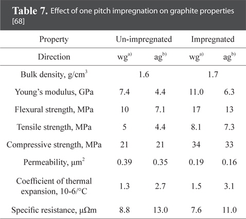
Effect of one pitch impregnation on graphite properties [68]
The variables affecting impregnation effect are as follows: 1) viscosity of the impregnant, 2) surface tension, 3) contact angle for impregnation, 4) reactivity during heat treatment, and 5) carbonization yield [76]. Table 8 presents a comparison of the binder pitch and impregnation pitch [77-79].
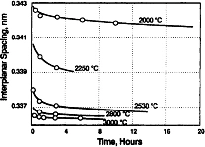
The graphitization cycle is smaller than carbonization, and takes several hours or up to three weeks depending on the size of bulk graphite. Graphitization causes the size of turbostatic crystallites (Lc) to increase from 5 to 100 nm. The inter-planar distance (d) of graphite crystals drops from 0.344 to 0.335 nm [5].
The graphitization mechanism underlying the increase in Lc and decrease in d is as follows: 1) removal of faults within faces and between planes in each graphite layer, 2) movement and growth of crystallites, 3) removal of cross-linked bonds, 4) development of -ABAB- stacking sequence, and 5) movement of carbon chains or single atoms to fill empty lattice spaces. Graphitization removes impurities existing in carbon and thus produces lighter bulk graphite [80].
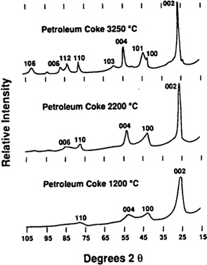
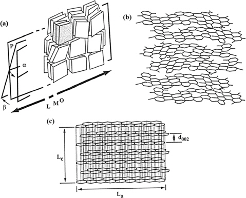
As shown in Figs. 10 and 11, most graphitization materials (coke) require a temperature of 3000℃ for complete graphitization and to satisfy the minimum distance between planes [81,82]. Fig. 12 shows the structure of bulk graphite produced from almost perfect graphitization. At 3000℃, the graphitization process takes two to three hours, or more at lower temperatures. This process can be accelerated by a metal catalyst or oxygen. The latter oxidizes disordered regions or elements interfering with graphitization, such as cross-linked bonds. An increase in pressure also reduces graphitization time [5].
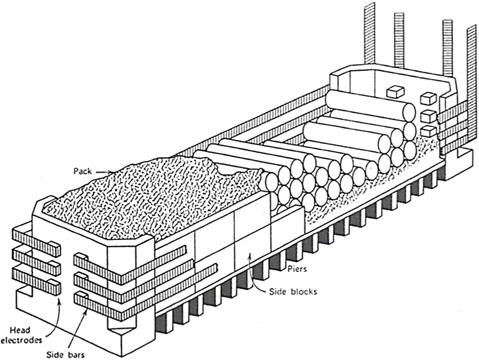
Graphitization can be classified into indirect heating and direct heating, each represented by the Acheson furnace [25] and lengthwise graphitization furnace (LWG) [24]. For the Acheson furnace (Fig. 13), packing coke surrounding the carbonized bulk graphite acts as the precursor, and heating is achieved through resistive heating. The LWG furnace provides direct heat to the carbonized bulk graphite, and the surrounding packing coke contributes to heat insulation and prevents oxidation. Due to this difference in heating, the cooling cycle takes one month for the Acheson furnace but only eight days for the LWG furnace. The latter is superior in terms of thermal efficiency and operating environment. The high-frequency inducting heating heats the crucible based on electromagnetic induction, thereby leading to higher energy efficiency and completing graphitization in a few hours [1]. However, this technology has yet to be verified.
Graphitization improves the heat and chemical resistance of bulk graphite, and also enhances thermal and electric conductivity
Purification of semiconductor components and bulk graphite requiring high purity, i.e. nuclear graphite, has developed in the three ways listed below.
1) Manufacturing of bulk graphite using pure filler or distilled filler
2) Thermal purification of bulk graphite. This performed at high temperatures due to dispersion of impurities outside of bulk graphite.
3) Chemical purification using halogens, which volatilize impure metals into halides.
The first method imposes many restrictions on filler selection. The second method is more economical compared to the other two methods, but does not completely remove the impurities. The third method gives purer bulk graphite, but involves more labor and costs. All three methods can be used together if detailed control is required over materials and processing. Table 9 presents the concentration of impurities after purification for a 4 by 4 in bulk graphite [83].
[Table 9.] Representative impurity levels of three classes of graphite [83]
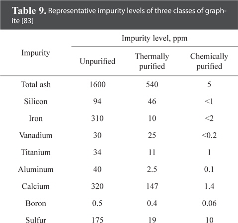
Representative impurity levels of three classes of graphite [83]
4.7.1. Thermal purification
Thermal purification involves heat treatment at 2800℃-3000℃, maintenance of maximum temperature for a day or two, followed by cooling. Impurities with low boiling points are removed in the processes up to graphitization. The remaining impurities form carbides or are substituted in the graphite lattice and exist in highly stable states. This method disperses atoms of impurities outside the bulk graphite. As such, bulk graphite with larger cross sections face greater constraints in size since it is difficult to eliminate all impurities [83].
4.7.2. Chemical purification
This method has been attempted using various gases such as sulfur hexafluoride, carbon tetrafluoride, and carbon tetrachloride but Freon-12 or chlorine is most widely used in the United States. Chlorine is used at 1000℃ under an inactive atmosphere, and Freon-12 at 2000℃. In the final stage, the remaining chlorine gas in porous graphite is removed. The reason for using Freon-12 at 2000℃ is that the generation of fluorine removes boron. Compared to other methods, chemical purification has no restrictions pertaining to bulk graphite size. Bulk graphite with impurities completely removed is used in nuclear graphite [83].
Artificial graphite in bulk form was defined as bulk graphite, and classified into isotropic and anisotropic bulk graphite. The materials, molding methods, and heat treatment process were discussed.
Isotropic bulk graphite has the same physical properties in all directions, whereas anisotropic bulk graphite assumes different physical properties in the molding direction and direction perpendicular to molding. The latter has different applications in each case.
Isotropic bulk graphite can be obtained using CIP, and anisotropic bulk graphite can be derived from compression and extrusion molding. The orientation can be adjusted depending on the materials and processes.
Carbonization occurs at 760℃-1200℃, and the removal of impurities from the green body leads to reduced weight and shrinking, giving it higher mechanical strength. The pores generated from removing impurities are filled with an impregnant, and carbonization is repeated.
The graphitization process requires temperatures higher than 3000℃. After graphitization, the distance between planes is reduced and crystallites grow larger. This increase in density allows the material to attain properties closer to those of graphite. Purification is carried out if necessary.

![Crystal structure of graphite showing ABAB stacking sequence and unit [35].](http://oak.go.kr/repository/journal/15753/HGTSB6_2015_v16n3_135_f001.jpg)
![The reactivity of graphite under various atmospheres and with different gases [19]](http://oak.go.kr/repository/journal/15753/HGTSB6_2015_v16n3_135_t001.jpg)
![Comparison of the CTE and CTE ratio of nuclear graphite, electrode graphite [33] and pyrolytic graphite [5]](http://oak.go.kr/repository/journal/15753/HGTSB6_2015_v16n3_135_t002.jpg)
![Flow chart for the manufacturing process of the general bulk graphite [35].](http://oak.go.kr/repository/journal/15753/HGTSB6_2015_v16n3_135_f002.jpg)

![Raw materials handling system [38].](http://oak.go.kr/repository/journal/15753/HGTSB6_2015_v16n3_135_f004.jpg)

![Properties of petroleum impregnating and coal-tar binder pitches [38]](http://oak.go.kr/repository/journal/15753/HGTSB6_2015_v16n3_135_t003.jpg)
![Particle sizes and characteristics of graphite grades [5]](http://oak.go.kr/repository/journal/15753/HGTSB6_2015_v16n3_135_t004.jpg)
![Molding techniques for bulk graphite [5].](http://oak.go.kr/repository/journal/15753/HGTSB6_2015_v16n3_135_f006.jpg)
![Characteristics of molding techniques [5]](http://oak.go.kr/repository/journal/15753/HGTSB6_2015_v16n3_135_t005.jpg)
![Tilting extrusion press [68].](http://oak.go.kr/repository/journal/15753/HGTSB6_2015_v16n3_135_f007.jpg)
![X-ray diffraction spectra of manufactured bulk graphite [30].](http://oak.go.kr/repository/journal/15753/HGTSB6_2015_v16n3_135_f008.jpg)
![Degree of alignment and anisotropy ratio from X-ray diffraction [30]](http://oak.go.kr/repository/journal/15753/HGTSB6_2015_v16n3_135_t006.jpg)
![Pitch impregnation system [68].](http://oak.go.kr/repository/journal/15753/HGTSB6_2015_v16n3_135_f009.jpg)
![Effect of one pitch impregnation on graphite properties [68]](http://oak.go.kr/repository/journal/15753/HGTSB6_2015_v16n3_135_t007.jpg)
![Diffraction patterns of petroleum coke as a function of graphitization temperature [5].](http://oak.go.kr/repository/journal/15753/HGTSB6_2015_v16n3_135_f010.jpg)
![Basal plane spacing as a function of time for various temperature of graphitization [5].](http://oak.go.kr/repository/journal/15753/HGTSB6_2015_v16n3_135_f011.jpg)
![Small distortions of nearly perfect graphite structure [5].](http://oak.go.kr/repository/journal/15753/HGTSB6_2015_v16n3_135_f012.jpg)
![The Acheson furnace [68].](http://oak.go.kr/repository/journal/15753/HGTSB6_2015_v16n3_135_f013.jpg)
![Representative impurity levels of three classes of graphite [83]](http://oak.go.kr/repository/journal/15753/HGTSB6_2015_v16n3_135_t008.jpg)