Studies on the control of inverted pendulum type systems have been widely reported. This is because this type of system is a typical complex nonlinear system and may be a good model to verify the performance of a proposed control system. In this paper, we propose the design of two fuzzy logic control systems for the control of a Segway mobile robot which is an inverted pendulum type system. We first introduce a dynamic model of the Segway mobile robot and then analyze the system. We then propose the design of the fuzzy logic control system, which shows good performance for the control of any nonlinear system. In this paper, we here design two fuzzy logic control systems for the position and balance control of the Segway mobile robot. We demonstrate their usefulness through simulation examples. We also note the possibility of simplifying the design process and reducing the computational complexity. This possibility is the result of the skew symmetric property of the fuzzy rule tables of the system.
Studies on the control of inverted pendulum type systems have been widely reported. This is because this type of system is a good model to verify the performance of a proposed controller for such a system, which is inherently a nonlinear. An inverted pendulum type mobile robot system adds mobility to the utilization of a mechanical function that balances the inverted pendulum system[1]. Furthermore, it is similar to the control scheme of a biped robot which is modelled after the human form and is supported by two feet.
Segway type mobile robots operate based on the dynamics of the inverted pendulum system. They are capable of forward, backward, and turning motions, and these are the only possible movements of the body. Unlike scooters whose two interdependent wheels are in series, Segway mobile robots have two wheels connected in a parallel configuration. Thus, Segway mobile robots allow the construction of a mobile platform that can travel smoothly to a small area by reducing the migration area. However, a mobile robot employing an inverted pendulum mechanism as its mobile platform requires an additional controller design to maintain the balance of the body, as its balancing ability is generally not good under excessive disturbances.
In this paper, we propose the design of a fuzzy logic control system for the position and balance control of an inverted pendulum type Segway mobile robot. We first introduce a dynamic model of the Segway mobile robot and analyze it. We then design two fuzzy logic control systems based on our analysis. Their usefulness is verified by simulation examples. Based on the skew symmetry property of the rule table for the fuzzy logic control system, we also present a possibility for a reduction in the computational complexity and the simplification of the design of the fuzzy logic control system.
The remainder of the paper is organized as follows. In Section 2, we describe the introduction of the dynamic model of the Segway mobile robot. The design of two fuzzy logic control systems for the Segway mobile robot is presented in Section 3. In Section 4, we present the results of simulation examples and explain their relevance. Concluding remarks are given in Section 5.
2. Dynamics of Segway Mobile Robot
Segway type mobile robots are composed of two wheels and a pole between them. The angle of the pole is measured by a gyro, tilt or acceleration sensor, and is maintained at zero degrees.
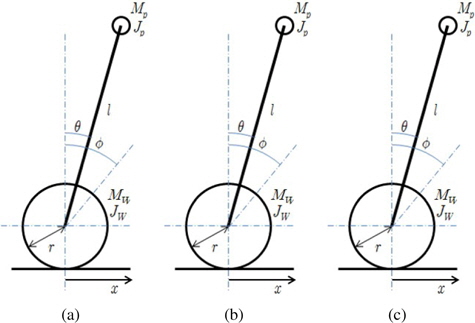
In this section, we introduce the dynamics of the Segway type mobile robot which is an inverted pendulum type mobile robot. Schematics of this robot are shown in Figure 1.
The main parameters used in Figure 1 are presented in Table 1.
[Table 1.] Definitions of Segway robot Parameters
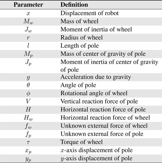
Definitions of Segway robot Parameters
As shown in Figure 1, the mobile robot can be divided into two parts. The wheel part and the pole part, which consists of a pole and a driving motor to support the body over the wheel and maintain the balance of the robot.
We first introduce equations associated with the wheel part of the robot, which is shown in Figure 1 (b). The following equations of motion are derived from the moment of inertia of the wheel of the driving shaft and the reaction forces of the horizontal and vertical axes of the pole:


The rotational angle of the wheel and the displacement of the robot have the following relationship.

From Eqs. (2) and (3), the horizontal reaction force of the wheels is derived from the displacement and the driving torque as

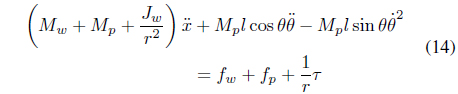
The following equation can be obtained from Eqs. (1) and (4).

We then derive the dynamic equations of the pole. The force acting the pole is shown in Figure 1 (c). Then the horizontal displacement of the center of gravity of the pole is

Eq. (6) can be expressed in an acceleration form as

Eq. (7) can be expressed as an equation of motion with respect to the axis of the center of gravity of the pole as


Next, the vertical displacement of the center of gravity of the pole is

Eq. (10) can be expressed in the form of an acceleration equation as

Eq. (11) can be expressed as an equation of motion with respect to the y axis of the center of gravity of the pole as


The following equation is derived from Eqs. (5) and (9).
The moment of inertia of the center of gravity of the pole is

The following equation is derived from Eqs. (9), (13) and (15).
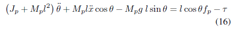
The dynamic model of the Segway robot is expressed by Eqs. (14) and (16).
3. Design of Fuzzy Logic Control Systems
Two fuzzy logic control (FLC) systems are required to control the Segway robot: the Distance FLC and the Balance FLC for position and balance control, respectively.
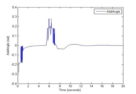
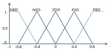
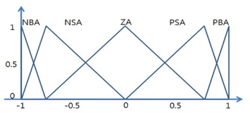
The Distance FLC to control the position of the robot is designed first. It has two input variables, edist and dedist, which are the error signal between the set position and the current position of the robot and its change signal, respectively. It also has one output variable, AddAngle, which is the weight of the angle error of the pole.
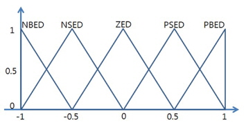
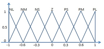
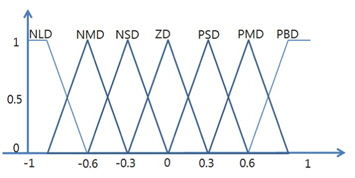
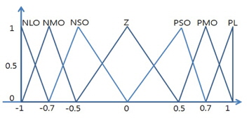
The membership functions of the input and output variables of the Distance FLC are shown in Figures 2, 3, and 4.
The control rule table for the Distance FLC is given in Table 2.
[Table 2.] Rule table for Distance FLC
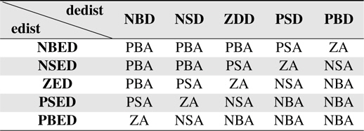
Rule table for Distance FLC
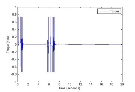
We then design the Balance FLC for the control of the balance of the robot. Its input variables are etheta and detheta, which represent the angle of the pole and the output of the Distance FLC. Its output variable is the torque.
The membership functions of the input and output variables of the Balance FLC are shown in Figures 5, 6, and 7.
The Z membership function for the output variable, torque, was widely set. The shapes of the membership functions of PLO and NLO are sharper than that of Z membership function. This can reduce the vibration of the output variable and make the output of the system converge to a steady state.
The control rule table for the Balance FLC is given in Table 3.
[Table 3.] IRule table for Balance FLC
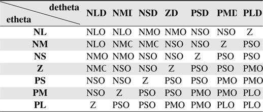
IRule table for Balance FLC
In this section, we simulate the position and balance control of the Segway mobile robot using the two proposed fuzzy logic control systems. We first set

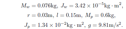
And some parameters of the Segway mobile robot are as follows[2]:
The AND and OR operations for the fuzzy logic control system are min and max, respectively. Additionally, Mamdani reasoning and the defuzzification method for the center of gravity are used in this simulation.
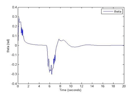
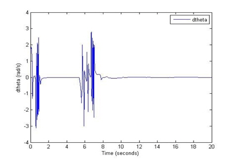
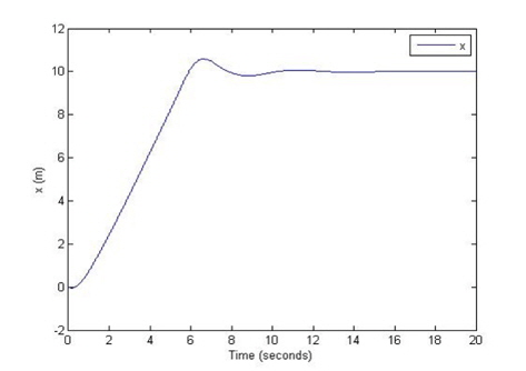
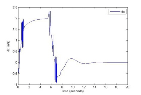
The results of the weight of the angle error of the pole, the torque, the displacement, the change in the displacement, the angle of the pole, and the change in this angle are shown in Figures 8, 9, 10, 11, 12, and 13 respectively. The initial conditions are as follows: the angle of the pole = 1 [radian], the target position is 10 [m].
In this paper, we analyzed the dynamics of the Segway mobile robot which has nonlinear properties, and designed two fuzzy logic control systems for the control of the position of the Segway mobile robot and the balance of the pole part of the robot. First, we designed the Distance FLC for the position control. The two input variables of the Distance FLC are the error signal between the set position and the current position of the robot and its change signal, the output variable is the weight of the angle error of the pole. We then designed the Balance FLC for the control of the balance of the pole. Its input variables of the Balance FLC are the angle of the pole and the output of the Distance FLC, and the output variable is the torque. The control rule table indicates that the control rules for the two fuzzy logic control systems are the skew symmetric[3].
This can simplify the control rule table to a single dimensional case with a small number of input variables and control rules. This in turn simplifies the design of the overall control system. This will be studied in future work with the implementation of an embedded board based system.