As civil infrastructures continue to deteriorate, the demand for structural health monitoring (SHM) has increased. Despite its outstanding capability for damage identification, many conventional SHM techniques are restricted to huge structures because of their wired system for data and power transmission. Although wireless data transmission using radio-frequency techniques has emerged vis-à-vis wireless sensors in SHM, the power supply issue is still unsolved. Normal batteries cannot support civil infrastructure for no longer than a few decades. In this study, we develop a magnetic resonance-based wireless power transmission system, and its performance is validated in three different mediums: air, unreinforced concrete, and reinforced concrete. The effect of concrete and steel rebars is analyzed.
As the deterioration of civil infrastructure continues, the demand for accurate and efficient structural health monitoring (SHM) techniques has increased rapidly. SHM techniques using various sensors, such as accelerometers, strain sensors, and piezoelectric sensors, have been investigated and their performance has been validated by many studies [1-3]. However, expensive and heavy wiring systems for each type of sensor used to transfer monitoring data and power restricts their use in large civil infrastructures. In recent years, wireless sensors for SHM have attracted significant attention, and notable advancements in wireless data transmission techniques have boosted the refinement of wireless sensors [4,5]. However, wireless sensors mainly rely on limited battery power, and battery power cannot support wireless sensors for the lifespan of civil infrastructure.
A new powering strategy is necessary to use wireless sensors. As an alternative, researchers have suggested energy harvesting, which can harness energy from the surrounding environment, such as vibrations and natural light [6-8]. Energy harvesting is considered a promising technique to power wireless sensors without human labor after the initial installation. However, the amount of power collected, from a few μW to mW, would not be sufficient to operate wireless sensors. In addition, specific conditions need to be satisfied in order to store the optimum level of energy. The wireless power transmission (WPT) technique has been considered another alternative, thanks to the following advantages: 1) a larger amount of power can be supplied and 2) whenever it is required, power can be transferred to the wireless sensors.
In recent years, Kurs et al. [9] proposed a WPT technique using magnetic resonance. Compared to the well-known inductive coupling-based WPT [10,11], this technique is advantageous to transfer power without sharp degradation of power transmission efficiency (PTE) despite of the increase of transmission distance. Many related studies have been undertaken to increase transmission distance and efficiency through air [12-17]. Jonah and Georgakopoulos [18] examined PTE through concrete and reinforced concrete (i.e., concrete with rebars), which are inhomogeneous mediums. While the study of PTE change induced by thickness and humidity variations in concrete was successful, the analysis of concrete and steel rebar effects on PTE is still insufficient.
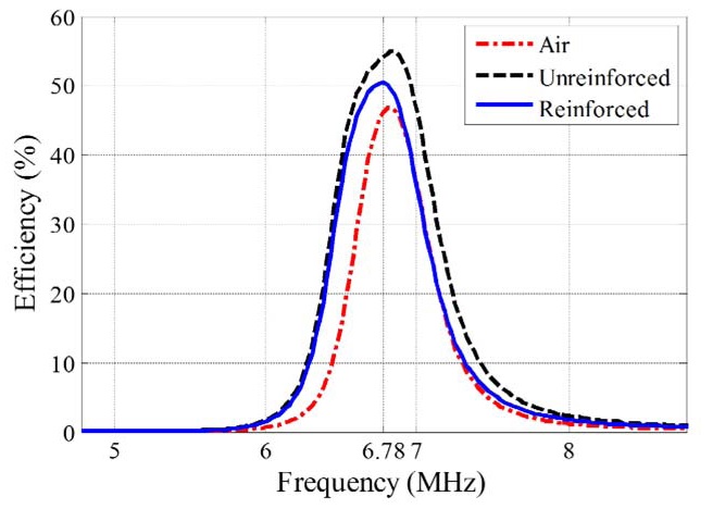
In this study, the magnetic resonance-based WPT (MRWPT) technique is investigated. Resonance coils of 6.78 MHz are optimally designed to achieve a high Q-factor, and coil-to-coil PTE is experimentally measured and compared for three different mediums: air, unreinforced concrete, and reinforced concrete. The effects of concrete and steel rebars are analyzed in terms of PTE change.
In Section II, we explain the fundamental principles of MR-WPT, and in Section III, we describe resonance coil design procedures. The PTE of the designed resonance coils is evaluated and compared for different mediums in Section IV. A brief summary and suggestions for future work make up Section V.
II. MAGNETIC RESONANCE-BASED WIRELESS POWER TRANSMISSION
MR-WPT is a mid-range WPT technique aiming to achieve power transmission distance of more than hundreds of millimeters.
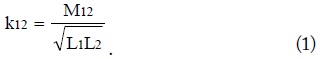
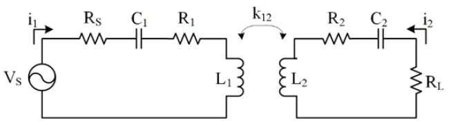
Fig. 1 is a simplified circuit model of MR-WPT consisting of the transmitting (Tx) coil, the receiving (Rx) coil, a power source, and load. Two resonance coils of the same resonance frequency are coupled through a magnetic field that lies between them Fig. and power is transferred from the power source to the load through the magnetic field [18-20]. The coupling coefficient (

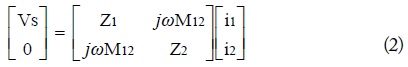
Eq. (2) is a node equation of the circuit model in Fig. 1.
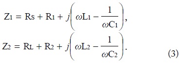
After solving Eqs. (2) and (3) against
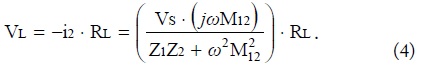
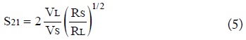
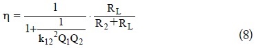
When the system is supposed as a simple two-port network, the amount of transmitted power can be quantified using the


III. DESIGN OF RESONANCE COILS
The design of the resonance coils is one of the most significant procedures to maximize PTE.

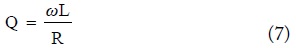
Q is a calculated Q-factor of a coil and
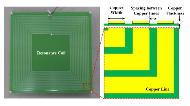
In this study, a printed spiral form is employed to assure system stability against external impact, and an analytical approach to design the printed spiral coil for WPT is used, which was proposed by Jow and Ghovanloo [21]. Its resonance frequency is tuned to 6.78 MHz, which is designated as the standard frequency for WPT by the Alliance for Wireless Power (A4WP) [22].
Several geometric restrictions are decided 1) coil size is fixed to 300 ×300 mm2 after considering convenience in practical uses, and 2) copper thickness and the spacing between copper lines are limited to 0.1 mm and 0.6 mm, respectively, because of technical limitations in manufacturing. Multiple design sets are produced in certain ranges, followed by previously determined geometric restrictions. The selfinductance, parasitic capacitance, and Q-factor of each design set are computed to determine optimum design parameters. For example, the number of turns from 4 turns to 15 turns, copper width from 1 mm to 10 mm, and spacing from 0.6 mm to 2.0 mm are assigned as the range of design parameters. Out of the computed design sets, one is picked that satisfies the following two conditions: 1) resonance frequency is between 6.78 MHz and 7.45 MHz and 2) the highest Qfactor is produced out of the design sets in condition (1).
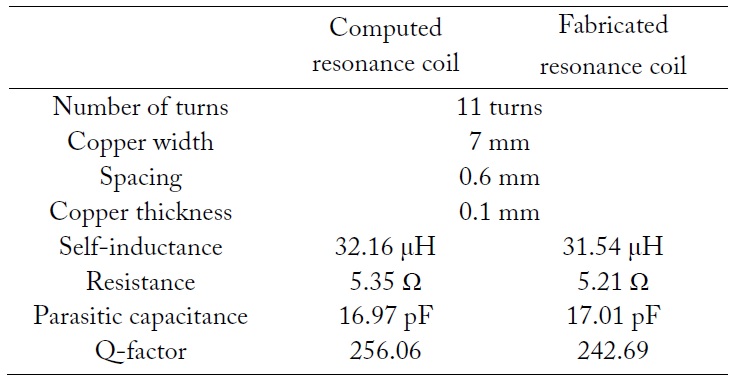
Table 1 shows the determined design parameters and electric specifications of each computed and fabricated resonance coil. Computed design parameters are well matched with the fabricated ones, meaning that the optimization process using the analytical approach is successful. Fig. 2 is the fabricated resonance coil according to the design parameters determined by previously mentioned procedures. Thanks to the stiffness of the printing substrate, the stability of the MR-WPT system is assured during the experiment.

Design parameters and electric specifications of each computed and fabricated resonance coil
In Section IV, the PTE of the designed resonance coils is experimentally measured for three different mediums: air, unreinforced concrete, and reinforced concrete. By observing the PTE changes of each condition, the effects of concrete and steel rebars on PTE are analyzed.
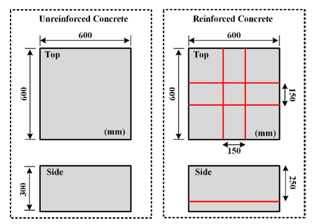
Two concrete structures are specially designed. One is unreinforced concrete and the other is reinforced concrete using steel rebars, the diameter of which is 15 mm. The mix proportioning and detailed geometric information are shown in Tables 2 and 3. In particular, not only the concrete thickness and the spacing of steel rebars but also the compressive strength are carefully determined while considering real concrete bridge construction. Blueprints for the manufactured concrete structures are shown in Fig. 3. Concrete size is 600 ×600 ×300 mm3, and steel rebars are placed at a 50-mm distance from the bottom.
[Table 2.] Mix proportioning for concrete structures
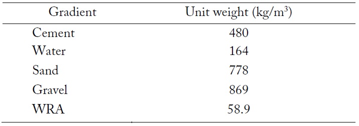
Mix proportioning for concrete structures
[Table 3.] Geometric information about concrete structures
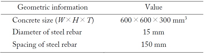
Geometric information about concrete structures
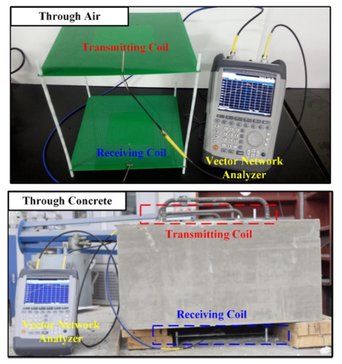
Experimental setups for PTE measurement using MRWPT through air and concrete structures are shown in Fig. 4. For both conditions, Tx and Rx coils are placed at the top and bottom, respectively, and the distance between them is fixed at 330 mm. In particular, Tx and Rx coils are 15 mm distant from the top and bottom surfaces of the concrete structure.
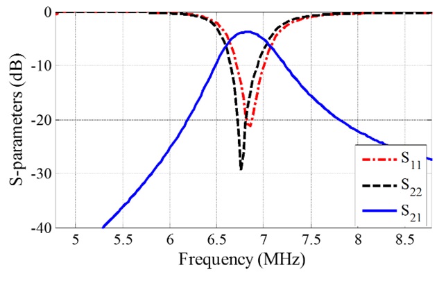
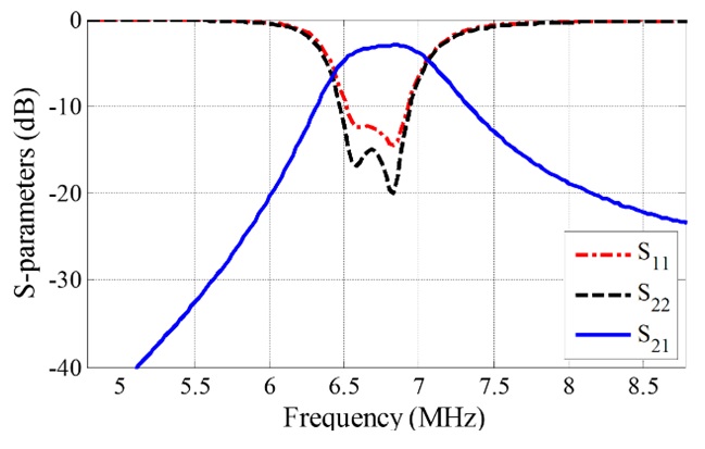
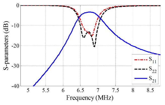
The reflection coefficients (
[Table 4.] Measured coupling coefficient (k) and mutual inductance (M) for each case
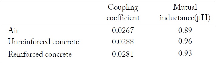
Measured coupling coefficient (k) and mutual inductance (M) for each case
On the other hand, steel rebars, which are conductors, definitely cause degradation of the PTE because of the reflections and eddy currents induced by alternating the magnetic field on their surfaces. In fact, the PTE of reinforced concrete is approximately 3% lower than that of unreinforced concrete, according to the experimental results.
In this study, an MR-WPT system was developed and the effects of concrete and steel rebars on PTE were examined using the developed system. The resonance coil with 6.78 MHz frequency was analytically designed to produce a maximum Q-factor. Unreinforced and reinforced concrete were specially designed following the construction conditions of real concrete bridges. PTE was measured and compared for three different mediums: air, unreinforced concrete, and reinforced concrete. Despite the expected reflections and attenuations of electromagnetic waves caused by the concrete structure, the existence of concrete induces improvements in the PTE. Concrete affects the generation of a magnetic field between resonance coils, and the detailed interactions are worth investigating numerically and analytically in future research. Comparing the results of unreinforced and reinforced concrete, it is proved that steel rebars of 150 mm spacing cause approximately a 3% degradation in PTE.
This study showed that MR-WPT is a promising technique to power wireless sensors in SHM for reinforced concrete structures. In the future, independent MR-WPT systems will be developed, including amplifying and rectifying circuits and the application to power wireless sensors. Finally, the applicability of the developed MR-WPT system for in-service reinforced concrete structures will be experimentally validated.