Switch mode power supplies (SMPS) that use converters are commonly used in today’s electronic products and industrial appliances. However, these converters are controlled by pulse width modulation (PWM), which means that electrical noise is generated due to rising and falling transients, and a common mode (CM) noise path is formed by the parasitic couplings in the circuit board. CM noise degrades system performance and may violate the regulations for conducted emissions.
A passive noise cancellation method has been proposed to reduce CM noise [1-3]. This method places a compensation winding in the transformer, thereby effectively reducing CM noise for buck, boost, buck-boost, and flyback converters.
The passive cancellation method can be applied to an inductor-inductor-capacitor (LLC) resonant converter as well. However, a direct application of the compensation winding used in other converters is not available, since the winding method in the LLC resonant converter is designed to obtain a large leakage inductance [4]. Therefore, a better approach needs to be considered when applying the passive noise cancellation method to an LLC resonant converter.
In this paper, we analyze the passive noise cancellation method for application to the LLC resonant converter. For the design of the compensation winding, we investigate the displacement currents flowing through the winding-to-winding capacitances in the transformer. By using circuit analysis and simulating the displacement currents, we propose a feasible connection method that can reduce CM noise. A prototype half-bridge LLC resonant converter is designed by applying the proposed connection method. The observed measurement results confirm that the passive cancellation method can effectively reduce CM noise for the LLC resonant converter.
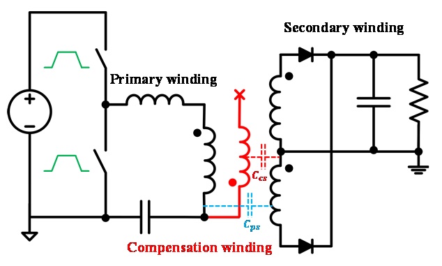
The circuit diagram that includes a compensation winding to reduce CM noise for a single-output half-bridge LLC resonant converter is shown in Fig. 1. The most dominant CM noise path is through the primary-to-secondary winding capacitance (
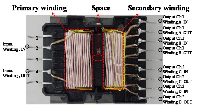
In this paper, we apply the compensation winding to the transformer shown in Fig. 2, which can be used for the dualoutput half-bridge LLC resonant converter. The transformer is for dual-output, so windings A and B constitute one of the outputs, and the other windings C and D are for the other output. Normally, the primary and the secondary windings overlap in the transformer to minimize leakage inductance. However, in the transformer shown in the figure, the primary and secondary windings are separated to obtain a large and controllable value of leakage inductance, because leakage inductance is used as the resonant-tank series inductance [4]. By overlapping with the primary winding through other pins, the compensation winding can be connected to the transformer. Therefore, the method to match the parasitic capacitances (
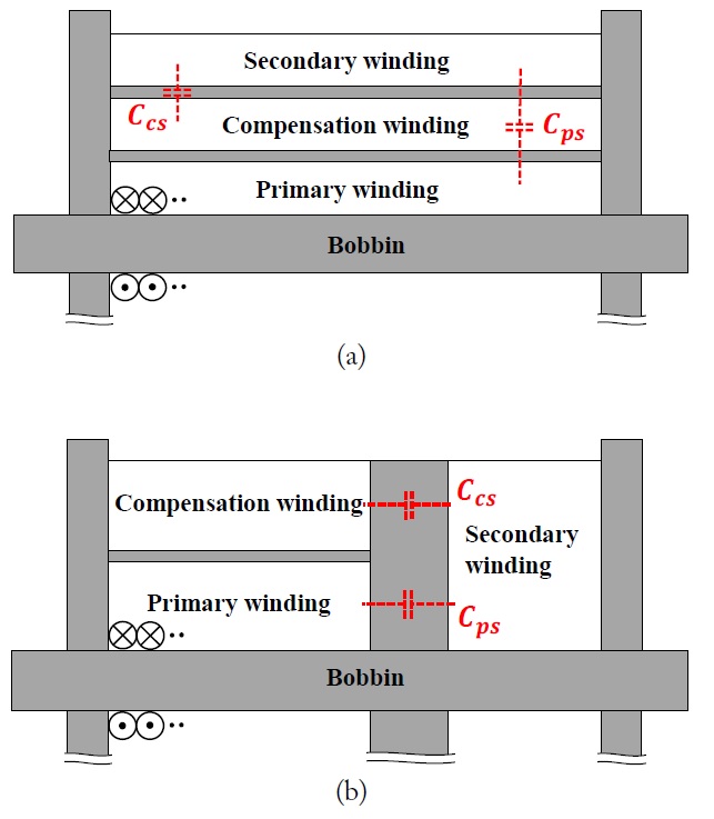
Cross sections of the upper sides of the transformers with compensation windings are described in Fig. 3. The traditional overlapped winding transformer shown in Fig. 3(a) requires the connection of an additional capacitor to the compensation winding [1,2], or adjustment of the compensation winding turn number [3], because
The compensation winding is added as an open circuit; therefore, it does not affect normal converter operation. This winding only produces a path for high frequency harmonics, which are generated by the rising and falling transients in the switches through the parasitic capacitance between the compensation winding and the secondary winding.
III. DISPLACEMENT OF CURRENT AND NOISE VOLTAGE
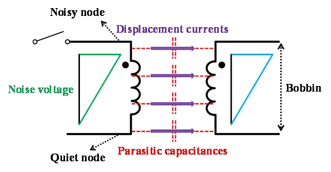
A description of the displacement currents in the transformer is shown in Fig. 4, where the node connected directly to the switches is named ‘noisy node’ and the other side is named ‘quiet node.’ The induced noise voltages along the primary and the secondary windings are indicated in the figure. We can see that the highest noise voltage is induced on the noisy node, and the noise voltage has the lowest value on the quiet node.
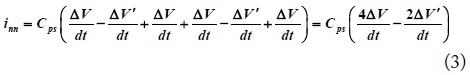
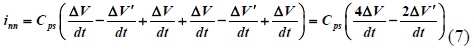
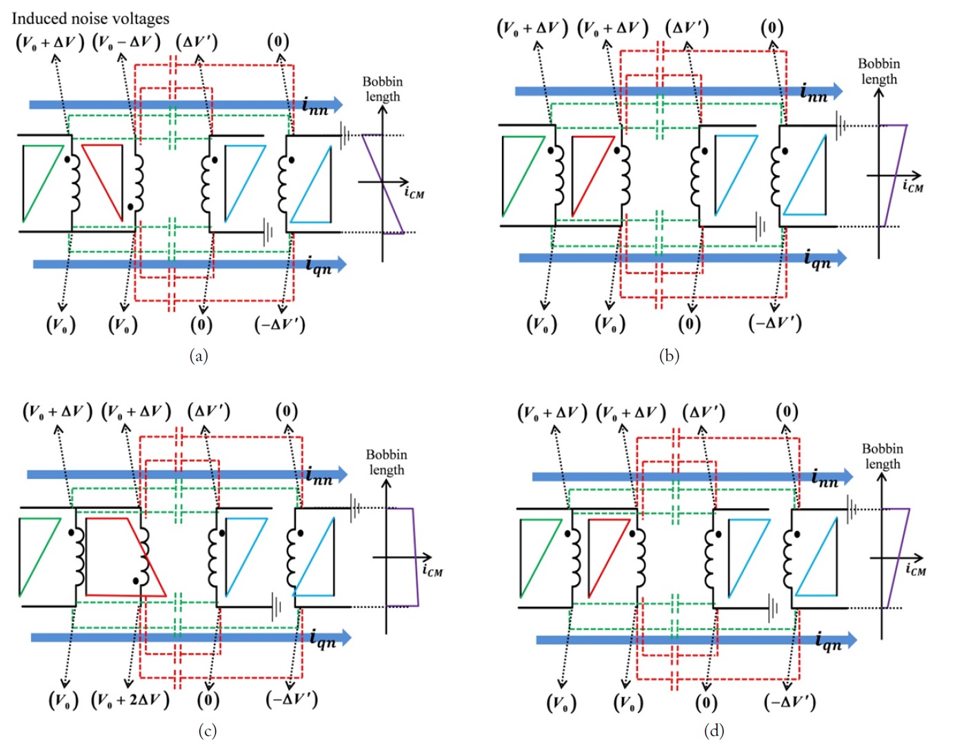
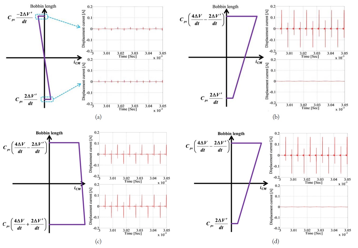
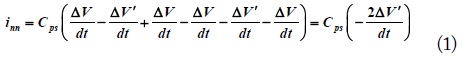
The compensation winding can be connected to the pri-mary winding in four ways, as shown in Fig. 5. The windings are constituted for a half-bridge and single output type. The single-output analysis can be applied to the dual-output case by a simple extension that includes additional windings in parallel. The connection methods are classified according to the connected node and the polarity of the compensation winding. With the induced noise voltage on all nodes, including the secondary winding, the displacement currents flow from the noisy and the quiet nodes to the earth ground. For the quiet node and the anti-polarity connection type, which are shown in Fig. 5(a), the displacement currents can be calculated as follows:
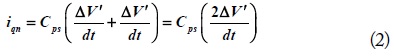
This analysis includes two assumptions. First, the parasitic capacitances have almost the same value (
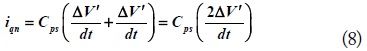
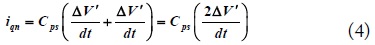
Similarly, the displacement currents for the other connection types can be calculated. The displacement currents for the quiet node and same-polarity connection shown in Fig. 5(b) are:

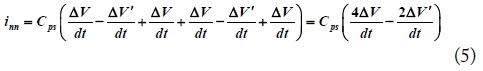
The displacement currents for the noisy node and antipolarity connection shown in Fig. 5(c) are:
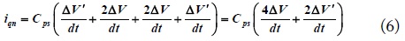
The displacement currents for the noisy node and samepolarity connection shown in Fig. 5(d) are:


The displacement currents along the bobbin length for each connection type are described in Fig. 5. The total CM noise current should be equal to the integration of the displacement currents along the bobbin length. In the case of the quiet node and anti-polarity connection, which are shown in Fig. 5(a), the distribution of the displacement currents between the quiet node and the noisy node is symmetrical along the
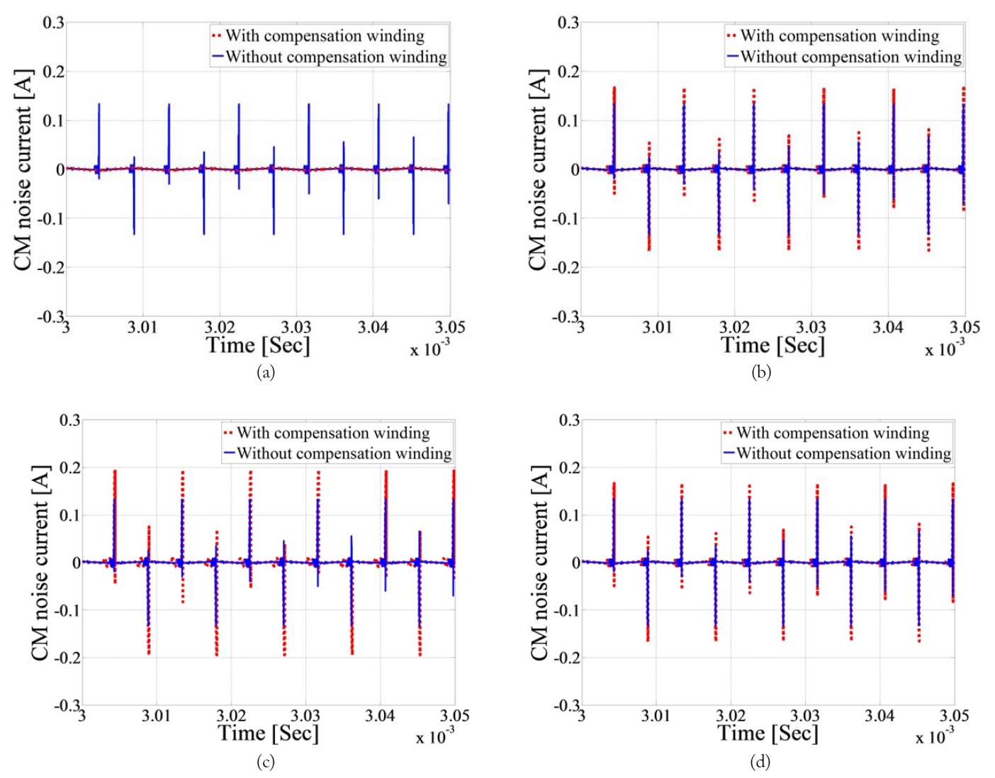
The simulation results of the displacement currents on the quiet and noisy nodes for each connection type are shown in Fig. 6. When we observe the magnitude and polarity of the simulated displacement currents, we find that the analyzed displacement currents in the previous section are in good agreement with the results of the circuit simulation.
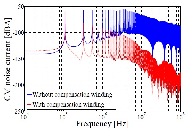
The total CM noise current for the LLC resonant converter can be calculated by adding all the displacement currents shown in Fig. 6; the results are shown in Fig. 7. In addition, the total CM noise currents for the converter with the compensation winding are compared to those of the original converters, which do not have the compensation winding. As shown in Fig. 7(a), the total CM noise can be reduced effectively only by the method of the quiet node and anti-polarity connection for the compensation winding. Otherwise, the total CM noise is increased. This corresponds with our expectations from the previous analysis.
Fig. 8 shows the CM noise current spectrum for the transient simulation results of Fig. 7(a). We can see that the CM noise current is decreased by almost 50 dB in the MHz frequency region. The low frequency region shows a difference of about 7 dB because the steady-state value of the displacement current of the with-compensation winding structure is increased by the additional capacitance between the compensation winding and the secondary winding. The simulation result verifies that the proposed passive noise cancellation method can effectively reduce CM noise.
A prototype circuit was designed for consumer electronic applications and measured to observe the effects of the proposed method in real applications.
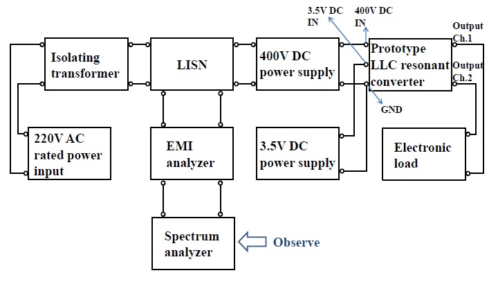
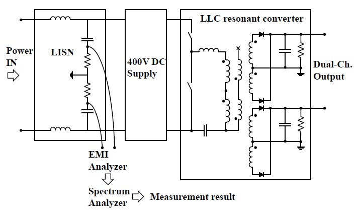
Figs. 9 and 10 show the measurement setup and the circuit diagram with measuring points. An isolating transformer was used to achieve a floating ground because the AC power input should be protected from possible CM and DM noise. Power can then be supplied to all the devices by connecting them to the isolating transformer. The prototype DC-DC LLC resonant converter with two transformers converts 400 V input to 24–6.5 A and 12–3.5 A dual-output, and the load current is controlled by the electronic load. The 3.5 V DC power supply is for the converter’s on-off switch. We can measure and extract the returned noise by using the line impedance stabilization network (LISN), as shown in Fig. 10. The CM and DM noises that are extracted by the LISN can be separated through the EMI analyzer. We can then observe the CM noise with the spectrum analyzer.
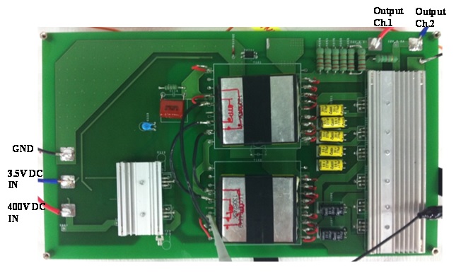
Fig. 11 shows the designed prototype LLC resonant converter. The input and output lines are indicated in the figure, and the lines are connected to other devices as shown in Figs. 9 and 10. The quiet node and anti-polarity method are used in the transformer to connect the compensation winding to the primary winding as shown in the circuit diagram in Fig. 10.
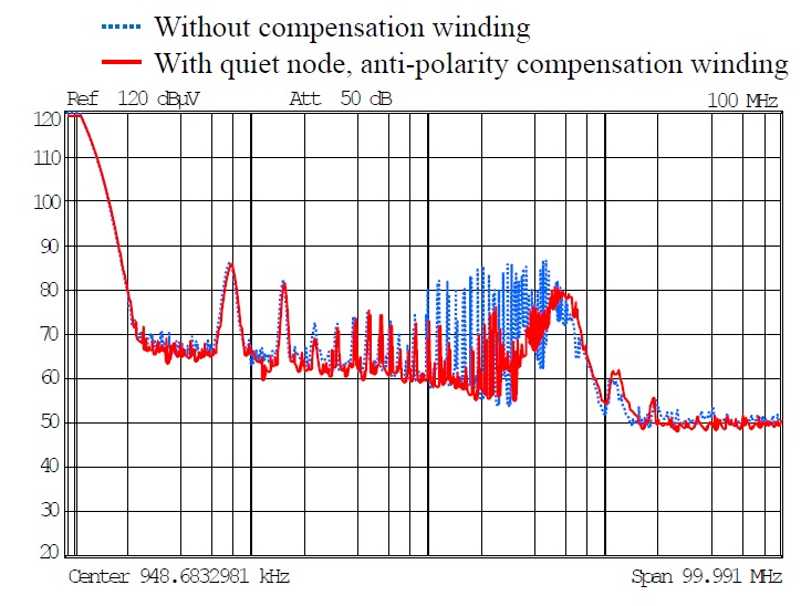
The measured CM noise voltage spectrums are shown in Fig. 12. Compared to the original converter, employing the compensation winding reduces CM noise by 10–20 dB in the frequency range of 1–7 MHz. Since the measurement result is for the voltage spectrum, it can be related to the simulation’s current spectrum in Fig. 8 by the impedance of the CM noise path. The measurement result shows smaller attenuation than in the simulation, because there are other contributions to the total conducted emission that cannot be eliminated by the proposed method. For example, emission through the heat sink and coupling between the line patterns in the converter circuit board can be directly conducted to the supply input without passing through the transformer. The effects of the additional noise become more dominant, especially in the high frequency region, and the proposed method is no longer effective. Nevertheless, both the simu-lated and measured spectrum results show a correlation indicating that CM noise can be effectively reduced from around the MHz frequency region when a significant amount of CM noise occurs in the converter. The measurement result indicates that the proposed passive cancellation approach is effective for reducing the CM noise of the prototype LLC converters in the frequency range of 1–7 MHz.
In this paper, we have examined the passive cancellation method for an LLC resonant converter. To match the parasitic capacitances, the compensation winding should have the same number of turns and a layer arrangement the same as that of the primary winding. Analysis of the displacement current confirmed that the quiet node and anti-polarity connection method using compensation winding is the only effective connection method for reducing CM noise. Use of a properly connected compensation winding reduced the CM noise by up to 20 dB in our frequency range of interest.