Uniform ZrO2 nanoballs were synthesized at 700℃ using the inverse replication method through a colloid-imprinted carbon (CIC) template. The structural, dielectric, and conducting properties of the ZrO2 nanoballs were investigated and compared with those of ZrO2 film prepared by sol-gel method and powdered ZrO2 chemical. Both the monoclinic and cubic phases were found in the ZrO2 balls and film but the ZrO2 chemical showed a monoclinic phase, where the cubic structure is known to be formed at above 2,300℃. ZrO2 nanoballs showed the lower dielectric property of k = 21.2 at 1 MHz because the 8-coordinated cubic phase in the ZrO2 nanoball produced lower polarization than the polarization of the 7-coordinated monoclinic ZrO2 chemical (k = 23.6). The dielectric stability was maintained in each ZrO2 ball, film, and chemical under the applied forward and reverse voltage range (−5 to +5 V) at 1 MHz. The ionic conductivities were 7.86 × 10⁻⁸/Ω·cm for ZrO2 nanoballs, 3.29 × 10⁻⁸/Ω·cm for ZrO2 chemical, and 6.70 × 10⁻⁵/Ω·cm for the thickness of 1,053 nm ZrO2 film at room temperature with the electronic contribution being less than 0.006%.
Since mesoporous carbon has been recognized as a catalyst in fuel cells, adsorbent, energy storage reservoir, and even a carbon based supercapacitor with the other advanced materials [1-7], a class of mesoporous carbon has been prepared through the nanocasting replication of mesoporous silica [8-11], through the imprinting of pitch with colloidal silica [12], or the imprinting of lignin gel and its carbonization [2]. The porous carbon replica was then successfully employed as a further template to achieve an inverse replica of mesoporous silica [13] or crystalline silica balls [14].
ZrO2 has emerged as a versatile material including a refractory material in insulation, abrasive, and enamel. It is used in dentistry because its excellent mechanical property is very similar to the strength of steel and its color is toothlike [15]. Nanocrystalline ZrO2 can work as a catalyst due to its large surface area [16]. Stabilized zirconia has been used in oxygen sensors and solid fuel cells because it allows oxygen ions to move freely through the crystal structure at high temperature as a high ionic conductor with a low electronic conductivity, which makes it one of the most useful electroceramics. Recently, ZrO2 has attracted interest in memory device applications as a candidate for the high dielectrics (k ≈ 25) of the gate-oxide layer in MOS transistors. ZrO2 replaces SiO2 which has been used as an outstanding low dielectric (k ≈ 3.9) but is no longer suitable with the recent downsizing due to the leakage currents from electron tunneling through the SiO2 dielectric [17].
In this study, nano-sized ZrO2 particles (85 nm) were synthesized by using the reversible replication method with colloid-imprinted carbon as a template, where the template was prepared from low-cost colloidal silica with a particle diameter of 85 nm imprinting on pitch. While the ZrO2 precursor is crystallized inside the carbon template, the template contributes to maintaining the round-ball shape and prevents ZrO2 nanoballs from aggregating each other at high temperature, because the strength of the carbon template is high enough to maintain its round shape. Until now, no experiment has been carried out through dielectric and conductivity studies for the nano-sized ZrO2 balls. In this experiment, the structural and electrical properties of the nano-sized ZrO2 particles were also investigated and compared with those of ZrO2 film prepared using the sol-gel method and ZrO2 chemical purchased from Sigma-Aldrich, USA.
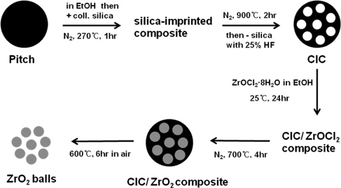
Colloid-imprinted carbon (CIC) was prepared by imprinting on pitch with colloidal silica according to the process described in the literature [12]. The brand name of the colloidal silica is Snowtes-ZL and its average particle diameter is 85 nm. 15.0 g of mesophase pitch carbon (Mitsubishi Chemicals) was dispersed in 150 g of ethanol and 60.0 g of colloidal silica suspension (40 wt% silica) was added. The mixture was then stirred overnight at 50℃ to evaporate during the stirring stage. It was further dried at 270℃, a slightly higher temperature than the softening point of the pitch under nitrogen flow for 1 hr. Meanwhile, the silicagel particles penetrated into the pitch and a composite was formed. The composite was carbonized at 900℃ for 2 hrs under nitrogen flow, and the silica was removed by dissolving the silica with 25% HF solution for one night. For the synthesis of the ZrO2 balls through the carbon template, 0.8 g CIC was added to 1.4 g ZrOCl2·8H2O which was dissolved in ethanol for one night in advance, and the mixture was shaken until the ethanol was vaporized at room temperature. The added weight of ZrOCl2·8H2O corresponds to 75% of the pore volume of CIC to prevent the formation of ZrO2 bulk. The resulting composite was heated under N2 flow at 700℃ for 4 hrs for the precursor, ZrOCl2·8H2O, to be converted to ZrO2 polycrystalline in the CIC template. ZrO2/CIC composite was then heated in air at 600℃ for 6 hrs to remove the CIC template. Fig. 1 illustrates the colloidal silica imprinting process for making CIC and the preparation process of the ZrO2 balls.
To synthesize the ZrO2 film using the sol-gel method [18], zirconium butoxide (Aldrich) was used as a precursor. The Pt substrate (1 cm × 1 cm) as a Pt film (1,500 Å) grown on the Ti layer (100 Å)/SiO2 adhesion (3,000 Å) on Si wafer (100) was purchased (Inostek Corp.). The substrate was primed with a hydroxide layer of 5 wt% 2-mercaptoethanol (Aldrich)/anhydrous ethanol solutions as the anchoring solution. 100 mM zirconium butoxide was dropped on the hydroxyl terminated Pt substrate in a dried N2-filled box, spin-coated for 3 min at 3,000 rpm/min, followed by pyrolysis at 450℃ for 20 min after 2~4 coating cycles. It was then annealed at 770℃ for 15 min to obtain a crystalline ZrO2 phase. According to DTA analysis, zirconium butoxide was decomposed at ~380℃. As the pyrolysis proceeded, cracks were formed. Thus, it was necessary to fabricate 10~15 multi-layer films by repeating the coating in order to cover the cracks shown in each layer and to avoid the possible electric short circuit during electrical measurement. The thickness of the ZrO2 film was measured using an α-step and an ellipsometer. Silver was then deposited on the film using a mask with electrode holes of 300 μm in diameter.
Before the electrical measurements were performed for the ZrO2 nanoballs and ZrO2 chemical, the powder samples of the ZrO2 nanoballs and ZrO2 chemical were pressed into cylindrical pellets and silver was then coated on both sides of each pellet as the electrode.
The phases of the ZrO2 nanoballs, film, and chemical were confirmed by x-ray diffractometer equipped with monochromated Cu Kα radiation. TEM images of the CIC and ZrO2 balls were obtained using a JEOL 100CX instrument.
The measurements of capacitance and resistance were performed at 1 MHz using a HP4192A LF Analyzer and HP4284A LCR meter at room temperature. The dielectric constant was estimated from the capacitance data by using the following equation,
k = Ct / (k0A)
where k is the dielectric constant, C is the capacitance, t is the thickness of the pellet or film, k0 is the permittivity of free space, 8.854×10⁻¹² F/m, and A is the area of the electrode. Electrical conductivity was estimated from the resistance data at ac (1 MHz) and dc conditions, which provided information on the ionic and electronic contributions in each ZrO2 sample.
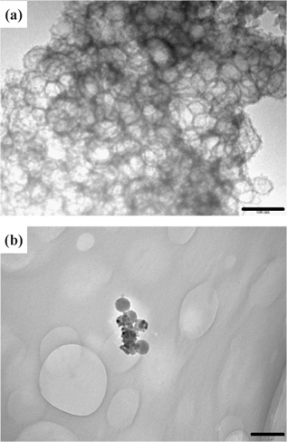
Figure 2(a) shows a TEM image of CIC prepared by imprinting the pitch with colloidal silica and Fig. 2(b) shows an image of the ZrO2 balls synthesized by following the process described in Fig. 1. The size of the ZrO2 ball in the image is quite uniform and almost equivalent to the particle diameter (85 nm) of the imprinted colloidal silica, indicating that the CIC template contributes to maintaining the ball shape during the crystallization of the precursor, and the ball size of ZrO2 can be controlled by selecting the proper size of the imprinting particle. However, a small number of ZrO2 balls were found, as seen in Fig. 2(b), because a low concentration of zirconium oxychloride precursor was added to penetrate the CIC and the precursor was decomposed inside the pore of the CIC with increasing temperature, resulting in the formation of partially pore-filled ZrO2 balls.
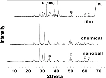
Figure 3 shows the XRD patterns of the ZrO2 nanoballs, film, and chemical. The phase of the ZrO2 chemical was monoclinic but the ZrO2 nanoballs and film showed two crystalline forms, a monoclinic phase, and a small portion of cubic phase. Especially, the peak of the film or nanoball shown at 2 θ = 30.04 in Fig. 3 is a unique peak of cubic structure. The four other peaks marked in the XRD patterns are the peaks that are overlapped by cubic and monoclinic phases. Two strong peaks of Pt and one peak indicating Si(100), where the Pt substrate on Si was used for the film deposition, were also observed in the XRD pattern of ZrO2 film. It is known that the 8-coordinated cubic structure is formed at above 2,300℃ compared with the stable 7-coordinated monoclinic structure at room temperature [19]. When the particle size is reduced to nano-size, different properties from the micro-sized particles are expected due to a relatively large surface area and high reactivity in the nano-sized particles. Thus, the appearance of the cubic phase at 700~800℃ in the ZrO2 nanoballs and film can be observed, producing different electrical properties from those of the monoclinic ZrO2 chemical. In other words, ZrO2 with a cubic structure has lower polarization and results in reduced dielectric property compared to the case of the monoclinic ZrO2, even though the nano-sized particles can be densely packed in pelleting at low temperature.
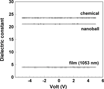
The dielectric constants (k) of the ZrO2 nanoballs and chemical estimated from the capacitances were 21.2 and 23.6 at 1 MHz. The k value of the ZrO2 film at 1 MHz was 3.78 for the film thickness of 705 nm and 3.98 for the thickness of 1,053 nm at room temperature. Although the pellet of the ZrO2 balls was denser and included less voids than that of the ZrO2 chemical, a lower dielectric property was observed because a small cubic portion of ZrO2 balls induced lower polarization, to a degree, compared with the monoclinic ZrO2 chemical. The lowest dielectric constant was observed in the ZrO2 film because the film also included a small amount of cubic phase, moreover, the film with cracks produced new voids in the process of pyrolysis. The dielectric constant of the voids might be almost the same as that of air (k=1.006). These defects induce the reduction of the dielectric property in a film. K. Natori et al. demonstrated that “the local dielectric constant at the edge site has a reduced value due to the absence of an enforcing field effected by the nearest neighbor dipole in the adjacent layer, which fact yields a smaller effective dielectric constant in a thinner sample structure” [20]. Therefore, the dielectric property of the film is influenced by the “interfacial effects” due to the surface layer/electrode and the existence of voids in the film. Regarding the total dielectric property, the relative portions of surface area and the space charge stored at the layer/electrode in the film are larger than those in bulk. As the measuring frequency increases and at 1 MHz, the capacitance formed at the layer/electrode can be partially extracted. However, the reduction of dielectric constant at high frequency is still observed due to the existence of cracks and voids in the thin film. In Fig. 4, ZrO2 nanoball, film, and chemical exhibit no significant difference in dielectric constant at voltage range, −5~+5 V, indicating that each ZrO2 sample is stable under applied forward and reverse dc bias sweeps (−5 to +5 V), with an ac oscillator level 10 mV at 1 MHz.
The electrical conductivity (б) was estimated from the resistance data (R) at 1 MHz by using the following equation,
ρ = R (A/t)
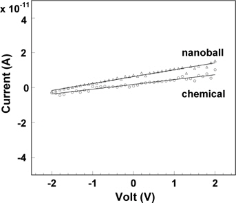
where ρ is resistivity, t is the thickness of the pellet or film, and A is the area of the electrode. The electrical conductivities (where б = 1/ρ at 1 MHz with an ac level of 10 mV) were 7.86 × 10⁻⁸ /Ω·cm for the ZrO2 nanoballs, 3.29 × 10⁻⁸ /Ω·cm for the ZrO2 chemical, and 6.70 × 10⁻⁵ /Ω·cm for ZrO2 film with a thickness of 1,053 nm at room temperature. Compared with the conductivity of the ZrO2 chemical, those of the ZrO2 nanoball and the ZrO2 film were approximately 2.4 times higher and 2,000 times higher, respectively. The results reveal that a fraction of the charge is not stored in the conducting system at high frequency, causing the reduction of charge polarization. ZrO2 film has enough defects in which the charge carriers can diffuse easily through the defects. The electronic conductivities of the pellet-shaped ZrO2 nanoballs and ZrO2 chemical were also performed through dc measurement at the applied voltage range of −2~+2 V. The resistance, R = V/I, was obtained from the reciprocal of the slope in the I-V graphs shown in Fig. 5. The total electrical conductivity is composed of the electronic part and the ionic part. The mobile ion is much heavier than the electron and moves very slowly at room temperature. The charge of mobile ions therefore cannot be stored at high frequency, such as at 1 MHz. However, when dc is applied on a sample, the mobile ions transferred at the opposite electrode no longer move, except for the electrons, resulting in electronic conductivity. The electronic conductivities were 2.49 × 10⁻⁸ /Ω·cm for the ZrO2 nanoballs and 1.82 × 10⁻⁸ /Ω·cm for the ZrO2 chemical at room temperature, confirming that the electronic contribution in ZrO2 was very low (< 0.003~0.006%). Thus, ZrO2 is an electronic insulator and its electrical conductivity comes from the ionic contribution by allowing oxygen ions to move through the ZrO2 system. Finally, the ZrO2 nanoballs with uniform pore size were synthesized using CIC in this research. The densified pellet of the ZrO2 nanoballs showed higher ionic conductivity with lower electronic contribution and lower dielectric constant than those of the ZrO2 chemical due to its unique structural and physical characteristics.
Uniform ZrO2 nanoballs were prepared using the inverse replication method through a colloid-imprinted carbon (CIC) template, indicating that the size, and the type of inorganic nanoball could be controlled depending on the selection of various imprinting compounds and precursors. Due to the increased reactivity caused by the large surface area in the nano-sized particles, the ZrO2 nanoballs can be transformed, reacted with other compounds, and densified easily at low temperature. The ZrO2 nanoballs synthesized at 700~800℃ showed two structural phases, cubic and monoclinic, even though the cubic structure is formed at above 2,300℃. Their physical and structural characteristics also influenced the electrical properties such as increasing the ionic conductivity and decreasing the polarization. However, all types of ZrO2, including nanoball, film, and chemical, maintained their dielectric stabilities at a voltage range of −5~+5 V.