This study aimed at conducting a flow analysis of the pressure distribution, discharge flow rate, and consequent thrust force according to the rotational speed of a three-dimensional screw propeller, and then investigating the effect of the rotational speed on the characteristics of the screw propeller by varying the relevant speed (3200, 2400, 1600, 800 rpm). In particular, the computational domain was considered by the analysis in the blades and outlet chamber, using boundary conditions. The difference between the minimum and maximum pressures was 5.5 MPa under the given conditions. The discharge flow rate at this pressure difference was on the level of 1956.67 kg/s, as a thrust force of 47083.7 T(N) was obtained. This study showed that the discharge flow rate linearly increased with the rotational speed, proportional to the RPM, while the thrust force was gradually and steadily increased with the relevant speed. In addition, it was proved that the occurrence of cavitation under the given conditions was closely related to the decrease in the durability of the screw propeller because the thrust force depends on the speed.
Most of all, a knowledge of the propulsive power enabled the size and mass of the propulsion engines to be established and the importance of function and role in the propeller was getting increased. High-speed craft on the propeller developed the changes in running attitude when it is under way. Compared with a conventional hull, this leaded to a number of measurements to be considered in the course of a resistance test. Because of the higher speeds involved, such craft may also be subject to water effects and supposed to face a serious damage such as corrosion and decrease of efficiency in the propeller.
Propeller used in the current market came from the propulsion design concept by Robert Hooke for his watermill design principle to gain energy from the dynamic mechanism (Kiam et al., 2014). Archimedean screw was implemented in propeller mechanism and Joseph Bramah was the inventor of screw type propulsion system for the stern of the ship (Carlton, 2007). Methods that were used to predict the hydrodynamic flow characteristics for various geometries included the computational and experimental approaches for propeller performance analysis.
However, enhancement of theoretical analysis has been continuously improved to coherently and effectively implement in the geometric design of marine. Analysis of propeller geometries started from two-dimensional hydrofoil with resultant forces and moments, followed by three-dimensional marine propeller that could best predict the performance in solid-fluid interaction. Nevertheless, predicting of flow in three-dimensional analysis being much more complicated due to its nonlinear flow behavior caused by the ship hull and wave effect has been attempted (Subhas et al., 2012).
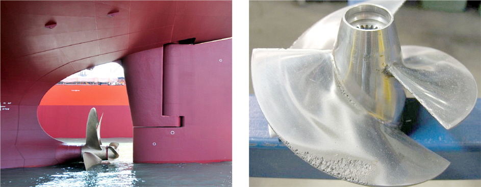
Mostly, cavitation occurs when the local fluid pressure drops to the vapor pressure of the liquid such as the pressure at which the liquid vaporizes. Especially, cavitation can occur on marine propellers where peaks of low pressure can arise, and this cavitation can affect the components of propellers and gradually decrease the durability of propeller, which means it is needed to reduce the probability of cavitation occurrence. In fact, cavitation could damage the poperties of screw propellers, gradually decreasing the durability of propeller. Most of all, occurrence of cavitation in the process of operating screw propeller can drop the efficiency of propeller and cause possible vibration and noise, and eventually induce the corrosion inevitable to the propeller (Molland et al., 2013). The actual image of screw propeller and its defects from cavitation are shown in Fig. 1.
The purpose of this study is to perform the analysis on the pressure distribution, discharge flow rate and consequent thrust force according to the rotational speed of the 3-dimensional screw propeller and then to investigate the effect of rotational speed on the characteristics of screw propeller, varying the relevant speed(3200, 2400, 1600, 800 rpm). Furthermore, the importance objective of this study is to find out discharge flow rate and thrust force on the given condition of rotational speed, clarifying the insightful relationship with the rotational speed. Especially, in the aspects that the thrust force on driving depens on the rotating speed, it was considered to reveal the relationship between the cavitation and the given rotating speed since occurrence of cavitation is closely related the decrease of durability of screw. In this study, the commercial code, FLUENT V13.0 was used in order to derive the discharge flow rate and thrust force in accordance with the rotational speed of the 3-dimensional screw propeller. Numerical method was used in the finite volume method and then the unstructured overset mesh method was considered.
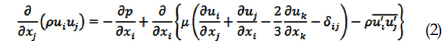
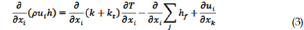
The incompressible turbulent flow in normal was assumed to simulate the flow field around the steady state of blade. Continuity equation of 3-dimensional and incompressible turbulent flow and momentum equation and energy equation are shown as follows.


The above introduced formula (1) and (2) are the momentum and continuity equation. Actually, Speed
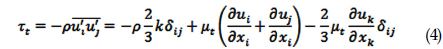
Turbulent flow as to the Reynolds stress is proportional to the average velocity gradient and the proportional constant is turbulent viscosity,

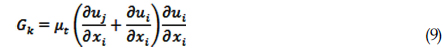
In this study, to obtain the viscosity of the turbulence model using a standard

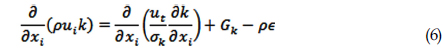
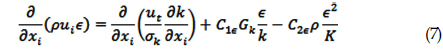
Factors,


3. Computational Domain and Boundary Conditions
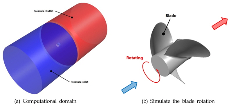
In this study, a considered computational domain is shown in Fig. 2 (a) and it was realized by the analysis in the blades and the outlet chamber. In addition, it was performed using MRF (Multiple rotating frame) analysis to simulate the blade rotation as shown in Fig. 2(b) (Homer, 2007; Tommy and Thomson, 1990; Versteea and Malalas, 1990).
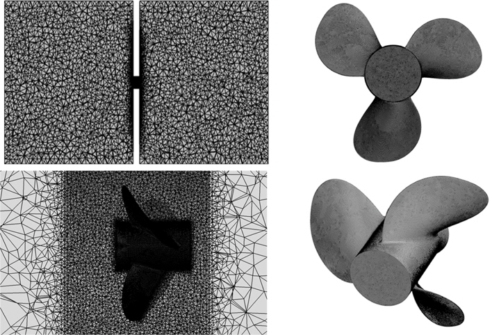
Inlet chamber was utilized in conditions of pressure inlet and outlet chamber was in conditions of pressure outlet. It was set up at atmospheric pressure to give an analysis. In addition, the analysis was performed according to the total of rotating speed (3200, 2400, 1600, 800 rpm). In this study, a total of 2,640,222 mesh was calculated in consideration of unstructured mesh in Fig. 3.
As referring to the below boundary conditions in Table 1, to investigate the effect of rotational speed on the characteristics of screw propeller such as pressure distribution, discharge flow rate and thrust force, the method of flow analysis was carried out. Especially, the analysis in every rotational speed was performed to consider the relationship between occurrence of cavitation in the given condition and the rotational speed of the 3-dimensional blade of screw propeller in the aspects that the thrust force on driving depends on the speed.
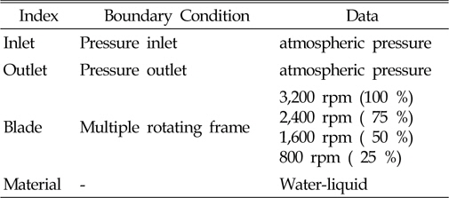
Boundary conditions
For this study, it was simulated by the flow phenomena around the propeller as to the rotational speed of 3-D blade and numerical analysis was performed in order to measure the flow rate around the propeller. The significant results were derived from the relevant analysis on the screw propeller.
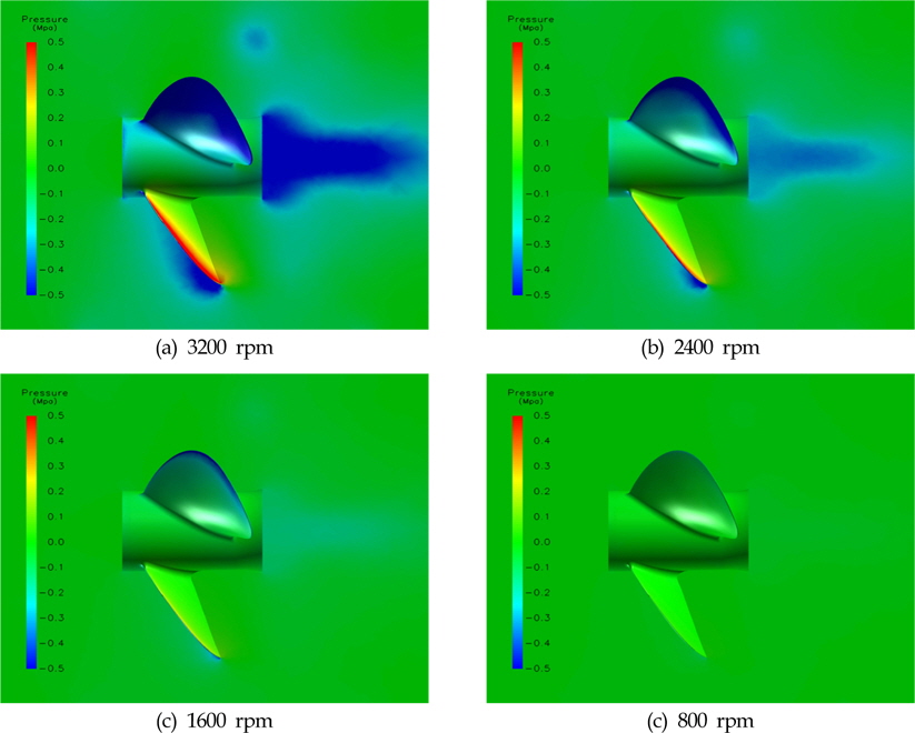
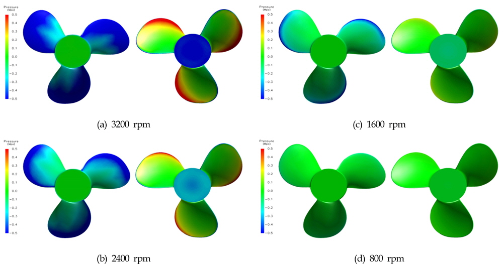
Figure 4 and Fig. 5 show the pressure distribution at each side, the front and rear of the propeller. In particular, in the point that 3-Dimensional approach might be appropriate, a view on the front, the rear and the side was utilized in the process of analyzing the pressure distribution.
The rotational speed on Fig. 4(a) and Fig. 5(a) was the fastest and it could be confirmed that there were the most significant pressure differences in case of Fig. 4(a) and Fig. 5(a), side and rear ends of the wings of the blade in the given rotational speed. Actually, the slower the rotational speed was, the more decreased the difference was, which indicates that pressure distribution was closely involved with the rotational speed of the screw propeller.
In the process of obtaining the maximum and minimum in the pressure differences, the reliable values could be acquired as varying the rotational speed. First of all, the maximum pressure as to 3200 rpm was about 1.3 MPa, as shown numerically, and the minimum pressure was approximately –4.2 MPa, and the difference was about 5.5MPa. Secondarily, the maximum pressure as to 2400 rpm was about 0.7 MPa and the minimum pressure was –2.4 MPa. In addition, the maximum pressure of 1600 rpm was about 0.3 MPa and the minimum pressure was about –1.0 MPa, which explains that the difference was about 1.3 MPa. Finally, the maximum pressure of 800 rpm was about 0.1 MPa and the minimum pressure was about –0.3 MPa. In this case, the difference was about 0.4 MPa.
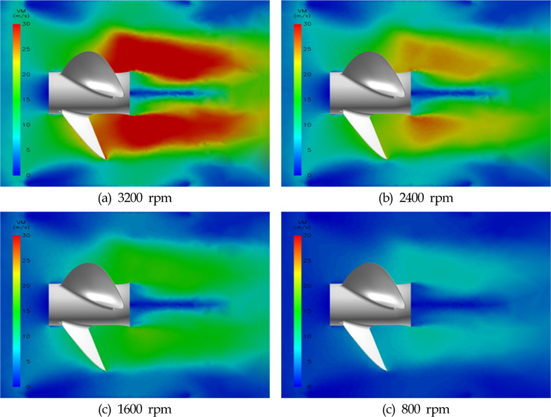
Figure 6 shows the speed distribution in a longitudinal direction of the propeller, respectively. As shown in Fig. 5(a), it was the most definite that speed distribution was quite affected by the rotational speed of screw propeller. The maximum speed as to 3200 rpm was about 55.84 m/s and the average was about 13.86 m/s, considering the maximum and average speed as to the rotational speed on the blade of screw propeller. The maximum speed as to 2400 rpm was about 41.88 m/s and the average was about 10.39 m/s, respectively. For the case of the maximum speed of 1600 pm, it was recorded as about 27.92 m/s and the average was about 6.93 m/s. Finally, the maximum speed as to 800 rpm was about 13.96 m/s and the average was about 3.46 m/s.
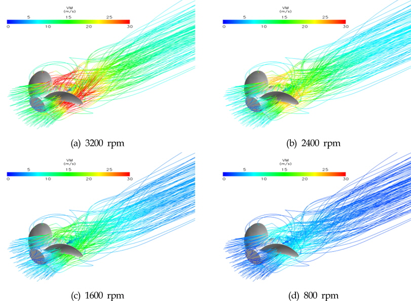
Figure 7 indicates the distribution of fluid flow around the propeller in accordance with the rotational speed, respectively. However, the variation of flow in accordance with the rotational speed difference was not large and there was only the difference of velocity magnitude. In this case, it could be derived, from the objective point of view, that fluid flow distribution was not much involved with the rotational speed of screw propeller.
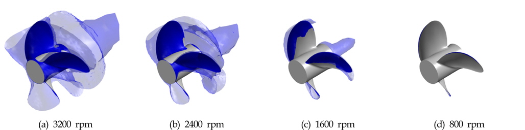
Figure 8 shows the distribution of the cavitation-generating region in relation to the rotation speed of screw propeller through the iso-surface plot. From the point of view, it is considered that cavitation is closely related to the fatigue life of propeller which means the durability in blades of screw propeller. If the water pressure is dropped by the rotational motion of the blades, cavitation will occur and the durability of the blades will be decreased. The cavitation occurred in all areas of 3200 rpm, high-speed rotation of the blade, even though the thrust force was obtained highest. However, it was observed that the cavitation-generating area showed the tendency to be reduced quite a little as the number of rotations was decreased.
According to the current surveys, it is reported that cavitation brings severe damages to the screw propeller as follows : (1) possible corrosion attributed to the collapse of cavitation bubbles, (2) possible vibration leading to blade fracture, (3) definite noise as cavities collapse, (4) flow along the surface to be disturbed (Schoenherr, 1963; Gawn and Burrill, 1957). Most of all, occurrence of cavitation can drop the efficiency of propeller and eventually induce the corrosion inevitable to the propeller, which means that it is needed, if possible, to reduce the probability of cavitation occurrence (Burrill and Emerson, 1963; Emerson and Sinclair, 1967).
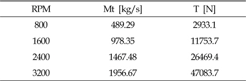
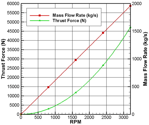
Discharge flow rate and thrust force by the rotational speed are shown on Table 2 and Fig. 9 as belows. As shown in Fig. 9, it was turned out that the mass flow rate was linearly increased with the rotational speed, proportional to the RPM. On the other hand, the thrust force was gradually increased with the rotational speed. Namely, the faster the rotational speed was, the more steadily increased the thrust force was. In consideration of the thrust force(N) on each RPM in Table 2 and Fig. 9, respectively, the thrust force showed the similar tendency, compared to the commercial studies.
[Table 2] Discharge flow rate and thrust according to the rotational speed

Discharge flow rate and thrust according to the rotational speed
Most of all, in the aspects that the thrust force on driving depends on the speed, the maximum thrust force was obtained in the condition of 3200 rpm. However, since occurrence of cavitation as to 3200 rpm can drop the efficiency of propeller and eventually bring serious damages to the propeller, the control and regulation of thrust force might be necessary. Therefore, it was considered that occurrence of cavitation, as shown in the condition of 3200 rpm, is closely related the decrease of durability of screw propeller.
The analysis was carried out on the pressure distribution, discharge flow rate and consequent thrust force according to the rotational speed. Especially, the analysis was realized focusing on the condition of 3200 rpm with respect to the rotational speed of the 3-dimensional blade of screw propeller. The conclusions obtained in this study are as follows :
(1) The greatest pressure occurred on the rear of the outward blade in the condition of 3200rpm. As a matter of fact, the difference between the maximum and the minimum was 5.5 MPa and the discharge flow rate as to the pressure difference was the level of 1956.67 kg/s in the condition of 3200 rpm, as the results pointed out.
(2) Pressure distribution was mainly investigated at each side, the front and rear of the propeller. With respect to rotation resistance and propulsion, the slower the rotational speed was, the more decreased the pressure difference was. Mostly, it was proved that there were the most significant pressure differences in the condition of 3200 rpm.
(3) In relation to speed distribution on the blade of screw propeller, speed distribution was quite affected by the rotational speed of screw propeller. The maximum speed as to 3200 rpm was up to 55.84 m/s in analysis of the flow speed around the screw propeller which seems to be normal due to its rotation.
(4) For driving force analysis, the thrust force(N) was gradually increased with the rotational speed of screw propeller, while the discharge flow rate was linearly increased. The thrust force of 47083.7 N was obtained in the given condition of 3200 rpm, a highest rotational speed of the propeller.
(5) The cavitation occurred in all areas of 3200 rpm, high-speed rotation of the blade, even though the highest thrust force was obtained. However, it was observed that the cavitation-generating area might be reduced quite a little as the number of rotations was decreased.
(6) Outcome of the analysis calculation was the test result in the stop mode in terms that the thrust force on driving depends on the speed. Actually, it was turned out that occurrence of cavitation, as shown in the condition of 3200 rpm, is closely related the decrease of durability as to screw propeller.