Surface modified carbon felts were utilized as an electrode for the removal of inorganic ions from seawater. The surfaces of the carbon felts were chemically modified by alkaline and acidic solutions, respectively. The potassium hydroxide (KOH) modified carbon felt exhibited high Brunauer-Emmett-Teller (BET) surface areas and large pore volume, and oxygen-containing functional groups were increased during KOH chemical modification. However, the BET surface area significantly decreased by nitric acid (HNO3) chemical modification due to severe chemical dissolution of the pore structure. The capability of electrosorption by an electrical double-layer and the efficiency of capacitive deionization (CDI) thus showed the greatest enhancement by chemical KOH modification due to the appropriate increase of carboxyl and hydroxyl functional groups and the enlargement of the specific surface area.
The shortage of water supplies for drinking as well as for industrial and agricultural uses is already a very serious problem. Desalination of seawater is considered one of the most practical solutions to overcome water shortages. To remove salinity from seawater, numerous desalination technologies have been developed, including thermal distillation, ion exchange, reverse osmosis, electric dialysis [1-5], and capacitive deionization (CDI). Among desalination processes, CDI has a number of advantages over other conventional desalination techniques, including lower energy consumption, inexpensive operating cost, and an environmentally friendly regeneration process [6]. CDI to remove ions from aqueous solutions is based on an electrosorption phenomenon occurring in an electrical double-layer formed at the interface of the externally charged electrodes. This electrosorption process is mainly dependent on the electrode surface properties such as the surface area, pore structure, pore size, and functional groups on the electrode surface. Porous electrode materials with high specific surface area are thus favorable for efficient electrosorption in the CDI process as well as high capacitive performance [7,8].
In this respect, activated carbon felts were utilized as an electrode for CDI to remove inorganic ions from seawater. The carbon felt consists of carbon fibers of small diameter with various porous structures, which can facilitate a more efficient electrosorptive reaction in an aqueous solution due to the high specific surface area. In this work, in order to increase the specific surface area and generate oxygen- containing functional groups on the electrode surface, the surfaces of activated carbon felts were chemically modified in alkaline and acidic solutions, respectively, and the electrochemical properties and the desalination efficiency of surface-modified carbon felts were investigated in terms of the specific surface area, and the changes of functional groups by chemical surface modification. For testing the CDI, a CDI unit cell was specially self-assembled, and an ion conductivity meter was used to monitor the change of ions in the NaCl solution.
Phenolic resin-based carbon felts (Kuraray Chemical Co., Japan) were prepared as a desalination electrode. For the purpose of chemical modification of activated carbon surfaces, carbon felts were treated in 1 M potassium hydroxide (KOH) and 1 M nitric acid (HNO3) solutions, respectively, at 90°C-100°C for 1 h. After etching using different solutions, the carbon felts were washed in deionized water at room temperature, and dried completely at 100°C under a vacuum for 24 h.
The surface morphology of the carbon felts was observed using a field emission scanning electron microscope (FE-SEM; JEOL, JSM 7600F, Japan), and the porous properties of the activated carbon felts were characterized by N2 adsorption at 77 K using a Micromeritics Model ASAP-2020 analyzer. The Brunauer-Emmett-Teller (BET) method was utilized to calculate the specific surface areas. Fourier-transform infrared (FTIR) spectroscopy (Hyperion 3000, Bruker Optics, Inc.) was used to detect oxygen-containing functional groups formed by surface modification.
A commercial electrochemical analyzer (IM6, Zahner Elektrik, Germany) was employed for cyclic voltammogram (CV) and impedance tests. The potentials for this measurement are referenced to a saturated calomel electrode (SCE), and a platinum sheet was used for the counter electrode.
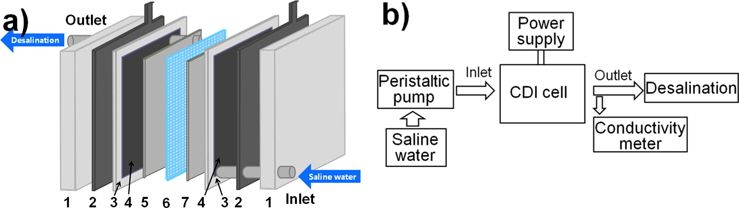
To evaluate the CDI efficiency, a CDI cell was specially prepared. The complete assembly was sandwiched between two Teflon plates. Fig. 1a shows the principle of CDI with the modified carbon felt electrodes. Modified carbon felts of 160 × 160 mm size were used as an electrode material of the CDI unit and they were placed face-to-face on both sides of a 0.7 mm thick spacer. Graphite foils were used as an inert current collector on the back side of the carbon felt electrodes. The CDI measurement system in Fig. 1b consists of the CDI unit, a peristaltic pump, a power supply, and a conductivity meter. A NaCl solution was pumped in by using the peristaltic pump from the bottom, and flowed out to the top of the unit. The applied potentials were 1.0 and 1.5 V in the tests with a flow rate of 50 mL/min. To evaluate the change in the concentration of the NaCl solution, an ion conductivity meter (YSI 3200) was used.
3.1. Surface characteristics of carbon felt electrode
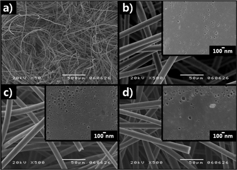
Fig. 2a shows the microfibrous structure of the carbon felts used in this study. The surface structure of the carbon felt is composed of a locked three-dimensional network consisting of modified carbon fibers of small diameter, typically 20-30 μm. The surfaces of carbon fibers without and with surface modification performed in KOH and HNO3 solutions, as shown in the close-up views of Fig. 2b-d, exhibit various pore sizes and distributions. Compared with non-treated carbon felt, large and highly dispersed pores were generated in the KOH modified carbon felt, as shown in Fig. 2c. On the other hand, larger and poorly dispersed pores were observed in the HNO3 modified carbon felt, as shown in Fig. 2d.
Proper size and distribution of pores on the carbon felt electrode are important factors affecting the electrosorption efficiency. In this context, nitrogen adsorption-desorption measurements were carried out and the pore size distribution was analyzed in order to more precisely investigate the pore characteristics of the modified carbon felts. Fig. 3 shows the nitrogen adsorption-desorption isotherms for modified and non-modified carbon felts. For all carbon felt samples, the adsorbed volume quickly increased with pressure in the low pressure range, suggesting that the adsorption isotherm is a type I pattern [9], where the adsorption is primarily related with microporous characteristics. An adsorption-desorption hysteresis loop was not observed in the isotherms of any of the carbon felts, indicating the absence of larger size pores.
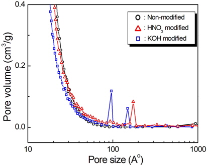
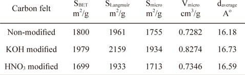
Fig. 4 shows the pore size distributions determined by a BET analysis of the surfaces of the carbon felts. Pores smaller than 2 nm are predominantly from the carbon felts with and without modification, indicating the existence of large numbers of micropores on the carbon felts. However, in contrast with the nonmodified carbon felt, pores with less than 2 nm were observed with the KOH and HNO3 modified carbon felts. Also, peaks in the pore size distribution curve were observed with the samples in a range of 10 to 20 nm. For the KOH modified carbon felt, large pores with diameters of 10 and 15 nm were present. In contrast, for the HNO3 modified carbon felt, relatively larger pores with diameters of 18 nm are exhibited. This can be explained by the observation that, in the case of the carbon felts modified in KOH or HNO3 solution, additional smaller and larger pores can be generated on the carbon felt by chemical etching during modification. Compared with the non-modified carbon felt, relatively smaller and larger pores were generated with the KOH modified carbon felt by proper chemical etching. On the other hand, compared with the KOH modified carbon felt, larger pores were formed in the HNO3 modified carbon felt. This may be attributed to severe chemical dissolution of the pores during HNO3 modification, leading to a decrease in the specific surface area. The results obtained by analyzing the isotherms show that the BET specific surface areas for the non-modified, KOH modified, and HNO3 modified carbon felts are 1800, 1979, and 1699 m2/g, respectively, as indicated in Table 1. These results indicate that the surface modification in the KOH solution leads to enlarged specific surface area due to the formation of a relevant pore structure whereas the specific surface area was decreased in the HNO3 modified carbon felt due to severe chemical etching.
[Table 1.] Physical properties of non-modified and modified carbon felts
Physical properties of non-modified and modified carbon felts
The porous properties of the modified carbon felts are summarized in Table 1. Here, the micropore surface (Smicro) and the micropore volume (Vmicro) were evaluated by the t-plot method, and the average pore diameter from the adsorption branch was calculated by the BET method using the following equation.

where Vt is the total pore volume and SBET is the BET specific surface area.
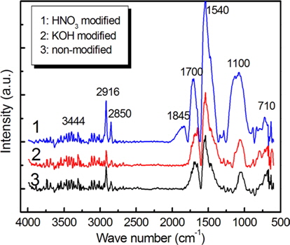
A FTIR analysis was performed in order to characterize the functional elements absorbed on the carbon felts. Fig. 5 presents the FTIR spectra of surface-modified carbon felts. Although the peak intensities varied, the overall shapes of the spectra were similar. Absorption peaks near 2916, 2850, 1700, 1540, 1100, and 710 cm-1 were observed in all of the carbon felts, irrespective of the surface modification. The absorption bands observed near 1700, 1540, and 1100 cm-1 are attributed to the characteristic carboxylic groups [10-13].
In particular, the absorption band observed near 1700 cm−1 is attributed to C=O bands characteristic of carboxyl functional groups (–COOH) and of ketone/quinine [14-16]. It has also been reported [13] that the band in the range of 1590-1570 cm−1 can be assigned to a combined band due to the aromatic ring mode of conjugated systems (diketone, ketoester, and carboxylate structures) and the absorption band at 1150 cm-1 is assigned to –C–O and –OH bonds in ether lactones, carboxyl, and phenolic structures. These bands are observed near 1540 and 1110 cm-1 in Fig. 5. In the case of the carbon felt modified by HNO3, the intensities of these bands are increased by an oxidation process. The band at 1845 cm-1 was observed with the HNO3 modified carbon felt due to newly formed carbon and oxygen functionalities, likely lactone and anhydride groups [17]. The FTIR spectra shown in Fig. 5 indicate that more oxygen-containing functional groups were generated by the HNO3 modification, such as carboxyl and hydroxyl (phenol) functional groups. In general, carboxyl and phenol groups are hydrophilic, and these compounds may promote the adsorption of inorganic ions by an ion-exchange reaction [18,19] in electrolyte.
3.2. Electrochemical behaviors
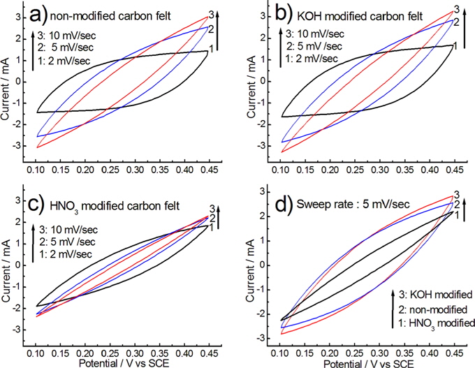
CV testing was performed to evaluate the electrochemical behaviors of the chemically modified carbon felt electrodes. Fig. 6 shows the CV curves of the chemically modified carbon felts, measured at a potential sweep rate in a range of 2 to 10 mV/s in a 0.5 M NaCl solution.
At a low sweep rate of 2 mV/s, voltammograms for the nonmodified and KOH modified carbon felts exhibit a low degree of distortion from the rectangular (box-like) shape, as shown in Fig. 6a and b. The rectangular shape in the CV curve represents ideal capacitive behavior due to the double-layer formation [20-22]. Thus, for non-modified and KOH modified carbon felts at a sweep rate lower than 2 mV/s, the motion of the electrolyte in pores on the carbon felt during the double-layer formation was not restricted relatively.
However, at higher scan rates, the responding current increased, and the CV profiles generally deviated from the rectangular shape due to a polarization effect and the ohm resistance to electrolyte motion in the pores [23]. Similar electrochemical behavior was observed with the non-modified and KOH modified carbon felts, as shown in Figs. 6a and b. For the HNO3 modified carbon felt, however, voltammograms with a sweep rate, as shown in Fig. 6c, represent a higher degree of distortion from the rectangular shape, and the induced current became smaller than that of the KOH and non-modified carbon felts. From the CV curves measured on all electrodes, as shown in Fig. 6, a steadily increasing and decreasing current was observed within the applied potential range, and they also showed no evidence that faradaic oxidation or reduction occurs in this range of potential. This indicates that ions adsorb on the electrode surface by forming an electric double-layer due to Coulombic interaction, rather than through electrochemical reactions [24].
For the responding current of the carbon felt at a sweep rate of 5 mV/s, as shown in Fig. 6d, high responding current was observed on KOH modified carbon felt, in comparison with other carbon felts. This highly responding current may be attributed to the increased BET specific surface area by the KOH modification. The responding current on the KOH modified carbon felt may be explained by the relationship between the conditions leading to the increase of specific surface area and the conditions leading to the formation of oxygen-containing functional groups on the carbon felt during chemical surface modification. This relationship is discussed in regard to the CDI in more detail.
The complex impedance was measured as a function of frequency in order to investigate the electrochemical behavior on the surface of the carbon felts. Electrochemical impedance spectroscopy experiments were performed at 25C in an unstirred and aerated solution of 0.5 M NaCl. All potentials are referenced to that of the a SCE. A platinum sheet was used for the counter electrode. The exposed geometrical surface area of the working electrodes in the electrolyte was 0.2 cm2.
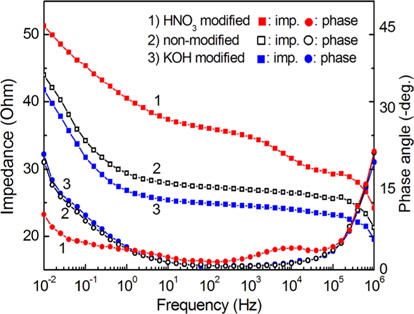
Fig. 7 shows the impedance spectra for the chemically modified carbon felts. The spectra are recorded at the open-circuit potential in frequencies from 10 mHz to 1 MHz. The spectra in Fig. 7 suggest that the high frequency region reflects the properties of the electrolyte, and the low frequency region reflects the surface properties of the carbon felt. The impedances at 10-2 Hz were 43.97 kΩ for non-modified carbon felt, 41.74 Ω for 1 M KOH modified carbon felt, and 51.27 Ω for 1 M HNO3 modified carbon felt. The impedance at low frequency can be correlated with the charge transfer resistance and the capacitance of the internal interface between the carbon felt surface and the electrolyte inside the carbon felt, as well as the surface functional groups attached to the carbon felt surface. For the carbon felt modified by KOH, as shown in Fig. 7, the surface impedance was lower than that of the other carbon felts in the applied frequency range. This lower surface impedance suggests that in the case of the KOH modified carbon felt, the electrosorption efficiency is higher than that of the other carbon felts, as well as the desalination efficiency in a NaCl solution.
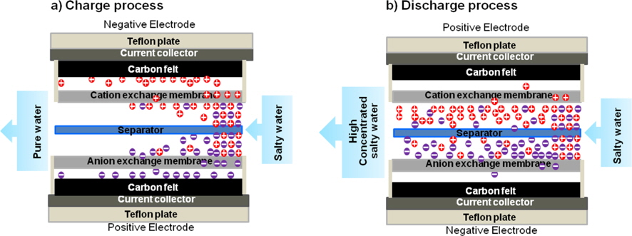
In order to evaluate the efficiency of the CDI properties, the CDI cell was charged with constant voltage. Upon applying different voltages between two carbon felt electrodes, cations are attracted into the negative electrode and anions into the positive electrode. As a result, fresh water can be produced from salty water. Fig. 8 shows a schematic of the basic mechanism of CDI.
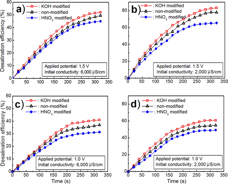
Fig. 9 shows the CDI of carbon felts in a NaCl solution with 2000 μS/cm and 6000 S/cm, at applied voltages of 1.0 and 1.5 V, respectively. The desalination efficiency was estimated using the following equation.
where λ
From the desalination measurement applying a potential of 1.5 V for 320 s for an initial concentration of 6000 μS/cm in a NaCl solution, the desalination efficiency was 49.5% for nonmodified, 52.1% for KOH modified, and 45.0% for HNO3 modified carbon felts.
As the initial concentration of the NaCl solution was decreased from 6000 μS/cm to 2000 μS/cm, the corresponding desalination efficiency was increased from 49.5% to 77.9% for non-modified, 52.1% to 83.3% for KOH modified, and 45.0% to 65.4% for HNO3 modified carbon felts, as shown in Fig. 9a and b.
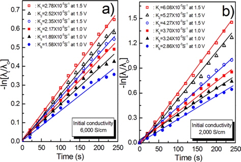
Meanwhile, as the applied potential of the CDI cell was decreased from 1.5 V to 1.0 V, the corresponding desalination efficiency decreased, as shown in Fig. 9c and d. The kinetic constants for the CDI process during desalination can be calculated by the first order reaction rate Eq. (3).

where C is the ion concentration in solution; Eq. (3) can also be rearranged to give Eq. (4).

For the desalination process, the ion concentration C corresponds to the conductivity λ, and hence Eq. (4) can be written as Eq. (5).

The kinetic constant thus can be expressed as Eq. (6).
where λo and λt are the initial (inlet) and resultant (outlet) conductivities, respectively.
The kinetic constants for the CDI process at 6000 and 2000 μS/cm and 1.5 and 1.0 V are illustrated in Fig. 10a and b.
The results of Figs. 9 and 10 indicate that the desalination ratio of the KOH modified carbon felt is superior to that of the other while the HNO3 modified carbon felt shows the lowest removal efficiency of inorganic salts. The CDI properties can be explained by the microstructure of the surface and the chemical functional groups formed on the surface of the carbon fiber during the surface modification process.
As revealed by the surface texture of the carbon fiber (Fig. 2) and BET measurement (Fig. 4), the KOH modified carbon felt exhibited high BET surface area and large pore volume, which lead to improved electrosorption ability.
Regarding electrosorption ability in relation to pore structures, Peng et al. [25] reported that the relevant KOH activation increases the specific surface area and ion diffusion channels in the surface, giving rise to enhanced electrosorptive ability. More oxygen-containing functional groups were generated by KOH chemical modification. This suggests that the KOH treatment is an efficient process to improve the electrosorption and desalination efficiency of carbon felts. However, for the HNO3 modified carbon felt, although it shows greater formation of functional groups by surface modification relative to the other carbon felts, as shown in Fig. 5, the BET surface area was significantly decreased due to severe chemical dissolution of the pore structure. This is attributed to a slight decrease in the efficiency of CDI. The capability of electrosorption by the electric double-layer and the efficiency of CDI on the activated carbon felts were thus enhanced by the KOH treatment due to the appropriate increase of carboxyl and hydroxyl functional groups and the increased specific area.
Surface modified carbon felts were utilized as electrodes for the removal of inorganic ions from seawater. In order to improve the efficiency of CDI, the surfaces of the carbon felts were chemically modified by 1 M alkaline and 1 M acidic solutions, respectively. The KOH modified carbon felts exhibited high BET surface areas and large pore volumes, and oxygen-containing functional groups were increased by the KOH chemical modification. Although there was much greater formation of functional groups by HNO3 chemical surface modification compared to the other carbon felts, the BET surface area was significantly decreased due to severe chemical dissolution of the pore structure. From cyclic votammogram measurements, highly responding currents were observed on the KOH modified carbon felt in comparison with the other carbon felts, indicating that the electrosorption efficiency of the electrochemical double-layer is superior to that of the other carbon felts.
From desalination measurement applying a potential of 1.5 V for 320 s, at an initial concentration of 2000 μS/cm in NaCl solution, the desalination efficiencies were 77.9% for non-modified, 83.3% for KOH modified, and 65.4% for HNO3 modified carbon felts.
The capability of electrosorption and the efficiency of CDI of the carbon felts showed the greatest enhancement by the chemical KOH modification, resulting from an appropriate increase of carboxyl and hydroxyl functional groups as well as increased specific surface area.