Insulation breakdown voltage and insulation lifetime were investigated in straight lines or twisted pairs with polyesterimide-polyamideimide enameled round wires (EI/AIW ). The enamel thickness was 50 μm and the conducting copper radius was 0.50, 0.75, 1.09, and 1.50 mm, respectively. There were many air gaps in a twisted pair therefore, when voltage was applied to the twisted pair, enamel erosion took place in the air gap area because of partial discharge according to Paschen’s law. Insulation breakdown voltage and insulation lifetime were highest in the sample of 0.75 mm conductor radius, which was higher than those values for 0.50 mm or 1.09 and 1.55 mm.
Polyesterimide-polyamideimide enameled wires (EI/AIW) exhibit good thermal and electrical insulation. Polyamide is a type of polymer that has high insulation breakdown strength, good resistance to heat and chemicals, and high mechanical strength. Therefore, polyamide-insulated wires can be used within harsh environments [1-3]. Polyamides are normally used in inverterfed motor windings and in high pressure coils for electric translators, and in recent years, elements allowing high-speed switching, such as insulated-gate bipolar transistors (IGBTs), have been developed as inverter power devices.
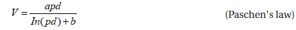
When voltage is applied to the twisted pair, the enamel film is eroded around the area with an air gap due to the partial discharge according to Paschen’s law [4-6]:

where V is the breakdown voltage in volts, p is the pressure in atm or bar, and d is the gap distance in meters. The constants a and b depend on the composition of the gas. With air at standard atmospheric pressure of 101 kPa, a = 4.36×10⁷ V/(atm·m) and b = 12.8, and the graph of this equation follows the Paschen curve. As a result, many researchers have also investigated the effect that high speed pulse waves with a short-term rise have on the insulation breakdown voltage [7-9]
This study therefore investigates the insulation breakdown voltage and insulation lifetime of straight-line and twisted-pair polyesterimide-polyamideimide enameled round wires (EI/AIW). The wires had an enamel thickness of 50 μm and the conducting copper radius was from 0.50~ to 1.50 mm.
EI/AIW was prepared by coating a round copper wire with polyesterimide-polyamideimide enamel (Sam Dong Co., Ltd., Korea). The enamel was coated to a thickness of 50 μm on wires with a conducting copper radius of 0.50, 0.75, 1.09, and 1.5 mm. Therefore, the total radius of the EI/AIW sample tested was 0.55, 0.80, 1.15 or 1.55 mm.
All twisted-pair wires were prepared by twisting two straightline wires with a length of 125 mm under a constant 1.4 N·m of torque that was applied by a twisting machine. The total length of all wires with different conductor radius was 125 mm, and the number of the twisted turns for the wires with a conducting copper radius of 0.50, 0.75, 1.09, and 1.50 mm was 22, 16, 16, and 13, respectively.
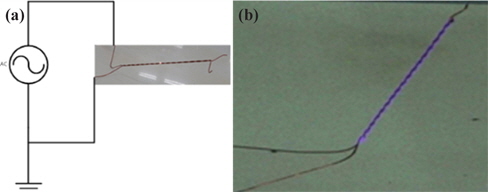
The insulation breakdown voltage and insulation lifetime of the straight-line and twisted-pair wires were studied by applying a sinusoidal waveform with a voltage of 0~12 kV at a frequency of 50~1,000 Hz by using a withstanding voltage tester (Model: APCP-12 kV-100, Sky Innotek Co., Ltd.) for frequency acceleration. Figure 1(a) shows the experimental setup of the partial discharge test. To apply a high voltage, the enamel insulation layer was removed from one side of the straight-line or twisted-pair wire, and the other side remained as-is without removing the enamel insulation layer. Then, the specimens were arranged on the withstanding voltage tester, as shown in Fig. 1(a), and light was emitted from the specimen, as shown in Fig. 1(b).
The insulation breakdown voltage was measured at a speed of 40 V/s until electrical insulation breakdown occurred. The insulation lifetime was also tested at a speed of 40 V/s until 6.25 kV, and it remained at that voltage until electrical insulation breakdown occurred.
3.1 Insulation breakdown voltage for straight lines
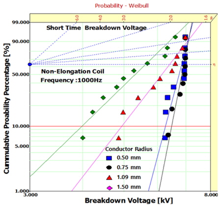
Figure 2 shows the Weibull statistical analysis (Weibull++ 7.0) of the insulation breakdown voltage for unelongated EI/AIW in the straight line form with various radii at 1,000 Hz. The parameters, such as the shape and scale, were obtained from the Weibull plots and are listed in Table 1. That is to say, parameter for the shape could be obtained from the slope of the data distribution, and the parameter for the scale indicated the AC electrical breakdown strength at which failure was expected with a cumulative 63.2% probability. The Weibull parameters that were obtained from Fig. 2 and those obtained at 69 Hz are listed in Table 1. The values for the insulation breakdown voltage were highest in the sample with a 0.75 mm conductor radius, regardless of the frequency, which was higher than those values for 0.50 mm or 1.09 and 1.50 mm.
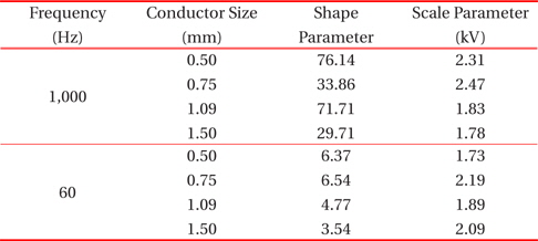
Weibull parameters for the insulation breakdown voltage of unelongated straight EI/AIW with various radii, as obtained from Fig. 2.
Table 2 shows the Weibull parameters for the insulation breakdown voltage of the straight EI/AIW with various elongation percentages at 1,000 Hz. The elongation varied from 0% to 30%, and voltage frequency was set to 1,000 Hz. The effect of the elongation was studied in order to simulate the realistic conditions under which electric equipment is manufactured. For example, when a motor and a generator are manufactured using enamel-insulated wire, the winding process is carried out under a constant torque. As such, the specimens are prepared under harsh conditions that cause elongation. In Table 2 shows that the insulation breakdown voltage values were the highest at an elongation of 0% regardless of the conductor radius. The values at an elongation of 0% 3 to ~4 times higher than those at a 10~ to 30% elongation. However, no differences were observed among the samples that had been elongated.
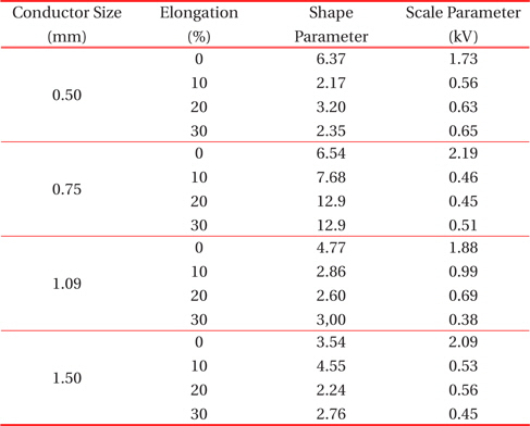
Weibull parameters for insulation breakdown voltage of straight EI/AIW with various elongation % at 1,000 Hz.
3.2 Insulation breakdown voltage for twisted pairs
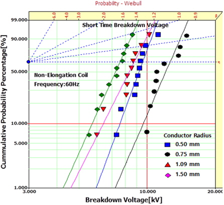
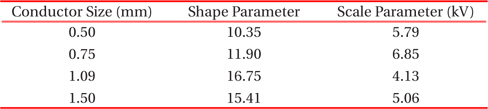
Figure 3 shows the Weibull statistical analysis of the insulation breakdown voltage for unelongated twisted-pair EI/AIW with various radii at 60 Hz. The parameters for the shape and the scale were obtained from the Weibull plots and are listed in Table 3. The insulation breakdown voltage values were the highest in the sample with a 0.75 mm conductor radius at 32~66% higher than those for the 0.5 mm, 1.09 mm, and 1.50 mm samples.
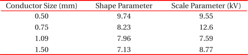
Weibull parameters for insulation breakdown voltage of unelongated EI/AIW twisted pairs with various radii at 60 Hz.
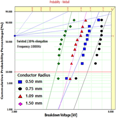
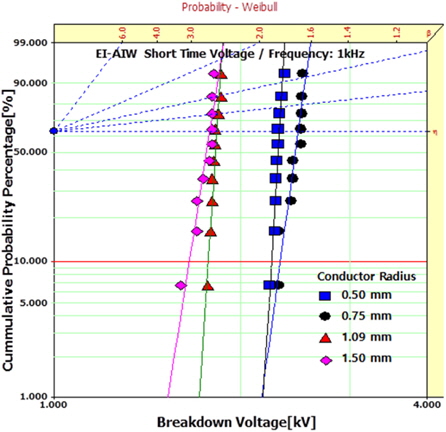
Figure 4 shows the Weibull statistical analysis of the insulation breakdown voltage for unelongated EI/AIW in the twisted pair form with various radii at 1,000 Hz. The parameters for the shape and scale were obtained from the Weibull plots and are listed in Table 4. The values for the insulation breakdown voltage were also highest in the sample with the 0.75 mm conductor radius with higher values than those of the 0.5 mm, 1.09 mm, and 1.50 mm samples.
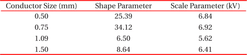
Weibull parameters for the insulation breakdown voltage of unelongated EI/AIW twisted pairs with various radii at 1,000 Hz.
The effect of the frequency was studied by comparing the values in Tables 3 and 4. For the wires with a 0.75 mm conductor radius, the insulation breakdown voltage at 60 Hz was 86% higher than that at 1,000 Hz, and the values at 60 Hz for the 0.5, 1.09, and 1.50 mm conductor radii were 38% higher than those at 1,000 Hz.
Figure 5 and Table 5 show the effect of the elongation on EI/AIW twisted pairs with various radii at 1,000 Hz. The insulation breakdown voltage values are the highest in the sample with a 0.75 mm conductor radius, which was 18~65% higher than the values for the 0.5 mm, 1.09 mm, and 1.50 mm. As the radius of the conductor increased, the size of the air gap increased so the partial discharge increased. However, the temperature between the wires increased as the conductor radius decreased. These results indicate that the gap size and the temperature affected on the enamel erosion. Therefore, the erosion rate of the enamel was the lowest in the sample with the 0.75 mm conductor radius, according to Paschen’s law [10,11].

Weibull parameters for the insulation breakdown voltage of the 20% elongated EI/AIW twisted pairs with various radii at 1,000 Hz.
The effect of the elongation was studied by comparing the values in Tables 4 and 5, and the insulation breakdown voltage of the unelongated systems was 16% higher than those of the 20% elongated systems.
3.3 Lifetime (V-t characteristic) for twisted pairs
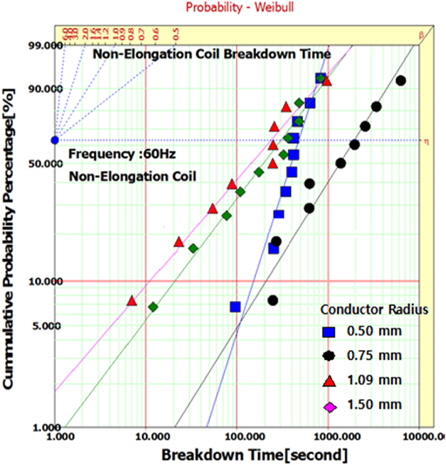
Figure 6 and Table 6 show the Weibull statistical analysis of the insulation breakdown lifetime for twisted-pair unelongated EI/AIW with various radii at 60 Hz. The insulation lifetime was carried out at a speed of 40 V/s until 6.25 kV, and it was maintained at that voltage until electrical insulation breakdown occurred. The shape and scale parameters were obtained from the Weibull plots and are listed in Table 6. The insulation lifetime was the highest in the sample with the 0.75 mm conductor radius, which was 440~890% higher than those values for the samples with a radius of 0.5 mm, 1.09 mm, or 1.50 mm.
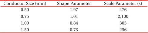
Weibull parameters for insulation lifetime for unelongated EI/AIW twisted pairs with various radii at 60 Hz.
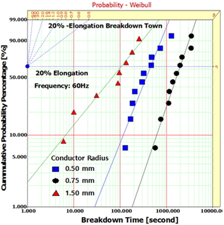
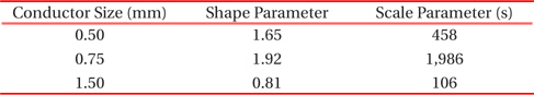
Figure 7 and Table 7 show the Weibull statistical analysis for the insulation breakdown lifetime of the 20% elongated EI/AIW in the twisted pair form with various radii at 60 Hz. The insulation lifetime was also tested at a speed of 40 V/s until 6.25 kV, and it was maintained at that voltage until electrical insulation breakdown occurred. The parameters for the shape and scale were obtained from the Weibull plots and are listed in Table 7. The insulation lifetime was

Weibull parameters for insulation lifetime for 20% elongated EI/AIW twisted pairs with various radii at 60 Hz.
The highest in the sample with the 0.75 mm conductor radius, which was 40~1,870% higher than those values for the samples with 0.5 mm or 1.50 mm.
The effect that elongation had on the insulation lifetime was studied by comparing the values in Tables 6 and 7. The insulation lifetime for the unelongated EI/AIW in the twisted pair was 6% higher than that of the 20% elongated systems.
The insulation breakdown voltage and the insulation lifetime were investigated in straight-line and twisted-pair round wires enameled with polyesterimide-polyamideimide(EI/AIW). The thickness of the enamel was 50 μm, and the conducting copper radius was of 0.50, 0.75, 1.09, and 1.50 mm, respectively. The insulation breakdown voltage was the highest in the sample with the 0.75 mm conductor radius, regardless of the frequency and elongation in straight-line or twisted-pair samples. The insulation lifetime was also the highest in the sample with the 0.75 mm conductor radius. The size of the air gap size and the temperature had an effect on the erosion of the enamel. The erosion rate was observed to be the lowest in the sample with the 0.75 mm conductor radius, according to Paschen’s law. The insulation breakdown voltage at 60 Hz was 86% higher than that at 1,000 Hz, and that of the unelongated system was ~16% higher than that of the 20% elongated system.