The ability to take electrocardiographic measurements while performing our daily activities has become the peoplechoice for modern age vital sign sensing. Currently, wet and dry ECG electrodes are known to pose threats like inflammations, allergic reactions, and metal poisoning due to their direct skin interaction. Therefore, the main goal in this work is to implement a very small ECG sensor system with a capacitive coupling, which is able to detect electrical signals of heart at a distance without the conductive gel. The aim of this paper is to design, implement, and characterize the contactless ECG electrodes. Under a careful consideration of factors that affect a capacitive electrode functional integrity, several different sizes of ECG electrodes were designed and tested with a pilot ECG device. A very small cotton-insulated copper tape electrode (2.324 cm2) was finally attained that could detect and measure bioelectric signal at about 500 um of distance from the subject’s chest.
While valuable time and money is being pumped into disposable wet electrocardiographic (ECG) electrodes every year, they still demand a long time on skin preparation making the procedure not suitable for a long term acquisition. They also pose comfortability issues like irritation, inflammation, and allergic reactions due the toxicological issue of the gel during prolonged use [1]. Moreover, in a situation where the wet electrode becomes separated from the skin or when gel dries out, it is no longer effective to pick-up biosignal with the required fidelity. This situation is mostly common in electrophysiological measurement of neonates who are usually moving during an ECG procedure. Even though the current wet ECG devices have impedance sensors for sensing electrode contact loss, neither the loss data is recovered nor is the operation of the system resumed [2]. These issues of wet ECG electrodes led to the invention of dry electrode. Dry electrodes do not require gel for bio-signal acquisition, but they also have issues such as poor electrode-skin contact and metal poisoning. A good contact is established by dry electrodes after perspiration, where the sweat acts as the electrolyte at the skin-electrode interface. There are two kinds of dry electrodes, namely stiff and flexible electrodes. Stiff electrodes have the tendency to slip over the skin during any slight movement, which may cause loss in electrode contact and some charging effects between the electrodes. Flexible electrodes are soft and have the ability to lie flat on the body surface; hence, they have a relatively higher contact area than stiff electrodes [3]. Both wet and dry electrodes experience huge distortion of electrophysiological signals during a high physical activity, due to the relative motion between electrodes and skin. The idea of measuring bio-signal without skin contact led to the evolution of another form of electrodes known as non-contact capacitive electrodes. Actually, this type of electrodes is not new, as Richardson et al were the first to detect and measure the bioelectric signals by using purely capacitive sensors [4]. Capacitive electrodes have the ability to measure bioelectric potential of human body in free space, without the use of any skin preparation or gel. Therefore, capacitive electrodes have eliminated the compatibility issues caused by wet and dry electrodes. However, sophistication in capacitive sensor system requires high capacitive coupling to the skin, which may require the use of foreign materials that may suffer from compatibility issues and be susceptible to electrode displacement [5]. Therefore, in this research, the degree to which the conductivity of the electrode, electrode area, insulator thickness, and the dielectric constant of the insulator affect capacitive electrodes fidelity would be examined into details.
2. PRINCIPLE OF OPERATION OF CAPACITIVE ELECTRODE
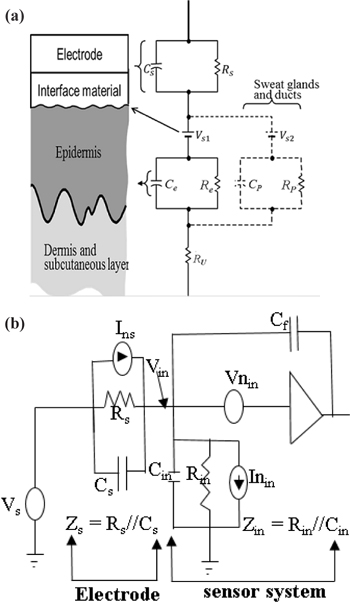
Measuring bioelectric signal without any direct ohmic contact with the skin requires the implementation of capacitive coupling. It involves a metal electrode, an insulator and the skin coupled together to form a capacitor, which enable electrophysiological measurement of bioelectric signal with minimal discomfort [6,7]. Fig. 1(a) shows the electrical connection between the body and the electrode via capacitive coupling. An electrode coupled to the skin via an interface material introduced a source inpedance, Zs which is a parallel combination of the source capacitance, Cs and resistance, Rs as shown by Fig. 1(a) and (b). The epidermis being the outermost layer of the skin is constantly renewing itself, and therefore plays an important role in the skin-electrode interface. Thus, movement of ions across the epidermis creates a potential difference, Vs1 across its membranes. Because the epidermis exhibits resistance, a viscoelastic and plastic behavior to the flow of ions across its membranes, it is found to have an electrical impedance that behaves like parallel ReCe circuits. Also, fluids secreted by sweat glands and ducts contain Na+, K+, and Cl- ions whose concentration differ from those in the extracellular fluid. This situation presents another set of potential difference, Vs2 which is in series with a parallel RpCp combination, as shown by the dotted lines in Fig. 1(a). The deepest part of the skin, known as the dermis and the subcutaneous layer, generally behaves as the pure resistive elements, Ru [8]. Capacitive electrodes measure this bioelectric signal in the form of electrostatic charges, whereby the main interest lies in the presence of charges rather than their flow. This measurement can be done in several ways, such as measuring charges directly, measuring the electric field, or measuring the actual spatial distribution of charges, since there is no standard way to do such measurements [9]. The general circuit for a capacitive electrode electrical model is shown in Fig. 1(b). A charge that flows onto a sensing electrode with area A [m2] and impedance, Zs at an electric field, E [V/m] is given by εOεrEA. As potential builds across the sensing electrode and the skin, a measureable quantity called capacitance is created. Also, if a known capacitance is allowed to give a charge a particular field strength E, it creates a measurable quantity known as potential difference across the coupling capacitor. For ultra high input impedance amplifiers used as buffers, current that flow from Zs due to spatial distribution of charges creates voltage, Vnin and current, Inin noise at the amplifier inputs. At lower frequencies, the amplifier input impedance, Zin is dominated by the input capacitance, Cin which gives a system a flat-band response of Vin = VsCs/(Cs + Cin). Therefore, in most circuit designs, the source capacitance, Cs is either made to be greater than or equal to the amplifier input capacitance Cin, so as to generate a near-ideal bio-potential measurement [2].
3. FACTORS THAT AFFECT THE PERFORMANCE OF A CAPACITIVE ELECTRODE
In order to identify the factors that govern the performance of capacitive electrode, two models are worth considering: mathematical model and experimental model. In the mathematical model, the first impression that comes to mind is to consider the capacitively coupled electrode as a simple capacitor as follows: capacitance, C = (εA)/t with ε = permitivity of insulator; A = area of electrode; and t = thickness of insulator. Varying these parameters cause a corresponding change in the capacitance between electrode and skin. For instance, an increase in either ε , A, or both results in a proportional increase in capacitance, whereas an increase in “t” results in a substantial decrease in C [10]. On the other hand, if the capacitive electrode is considered as an induced charged plate that generate an electric field E, then the mathematical model becomes V = (εOεrEA)/C, where voltage V is the measureable quantity, εO = permitivity of free space, εr = relative permitivity of insulator/medium, and C = capacitance across the coupling capactor. In this case, by increasing the electric field and the distance between electrode and skin, the voltage is increased.
The experimental model was verified by using five electrodes of different sizes. A pilot ECG device was fabricated together with the five electrodes. These electrodes were then tested with the pilot device to confirm and analyze the degree to which the factors in the mathematical model affect the electrode fidelity to be used for vital signs sensing. The following key factors were considered during the testing of the electrodes.
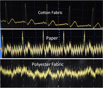
Permittivity of inserted material: The effect of dielectric constant of the interface material was examined by capping 9 cm2 electrodes with a layer of insulator. Electrodes insulated with polyester fabric (Mylar) formed ‘polyester electrodes’, those insulated by Paper were called ‘paper electrodes’ and that of cotton fabric formed ‘cotton electrodes’. An ECG recording was then taken for each electrode type, on the 24 year old subject.
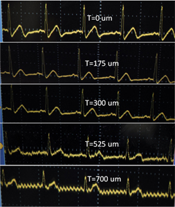
Thickness of interface material: Cotton sheets with 175, 350, 525, and 700 μm thickness were designed. First of all, an ECG recording was obtained by placing 2.324 cm2 electrodes directly on the skin without any interface material. Secondly, the 175, 350, 525, and 700 μm cotton sheets were placed one after the other between the 2.324 cm2 electrodes, on the chest of a 24 year old subject. ECG recording was obtained from each cotton thickness.
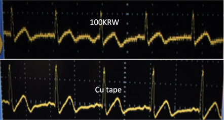
Conductivity of electrodes: The influence of conductivity was investigated by using two dissimilar circular electrodes of area 2.324 cm2; a copper electrode, and a 100 Korean won coin (fusion of copper, nickel, and silver). Each electrode type was used to measure the heart bioelectric signal of a 24 year old subject.
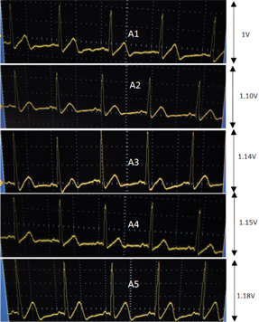
Electrode area: Five different sizes of flexible electrodes, with the areas A1=2.324 cm2, A2=9 cm2, A3=12 cm2, A4=15 cm2, and A5=18 cm2, were fabricated by using a copper tape (Copper tape, Tae Hwa). Each electrode was then insulated with cotton fabric by inserting it into a cotton pocket of thickness 175 μm. An ECG was recorded for each electrode area on a 24 year old subject with no history of cardiovascular diseases.
Table 1 summarizes the parameters and conditions involved in the determination of the degree to which the above mentioned factors affect the capacitive electrode fidelity.
[Table 1.] A summary of the parameters involved for the determination of each factor’s influence.
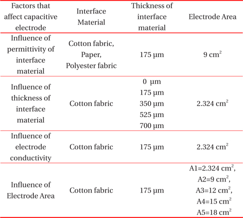
A summary of the parameters involved for the determination of each factor’s influence.
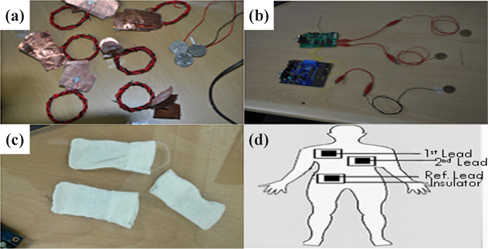
Each fabricated electrode type, as shown in Fig. 2(a), was connected to the pilot ECG device as shown Fig. 2(b). The connected electrodes in Fig. 2(b) were then placed into an interface material of cotton pockets shown in Fig. 2(c). The electrodes inside of the cotton pockets were then placed on the chest of a 24 year old male subject with no history of any cardiovascular disease. Fig. 2(d) shows the electrode placement on the subject chest. The 24 year old subject was then made to wear a tight Nike Pro Combat Fit to provide an adequate pressure on the coupling and also to keep the electrodes from displacement.
Taking a look at the figures below, Fig. 3 shows the influence of cotton, paper, and polyester as interface materials on the output ECG signal. Cotton fabric as an interface material gave a very good quality signal than the paper and polyester. This is because the cotton fabric has a higher dielectric constant (εr = 7.1) than the paper (εr = 3.5) and the polyester fabric (εr = 3.1), since the electrode area and thickness used for each interface materials were a constant. Paper has a dielectric constant lower than cotton, and it gave very noisy ECG signals even though the QRS peaks were visible. Polyester fabric has the lowest dielectric constant, and it did not give any ECG signal other than noise.
The signal quality of dry contact ECG recording (insulator thickness, T=0 um), as shown in Fig. 4, was not as good as that of noncontact electrode with insulator thickness of 175 um. This is because of the poor contact effect of dry electrodes due hair and high impedance of the skin. However, the signal magnitude was reduced when the cotton fabric thickness was increased to 300 μm. A further increase in cotton thickness of up to 525 μm gave a noisy bio-signal, even though the QRS peaks were visible. The bioelectric signal was reduced to a small noisy signal when a 700 μm thickness of cotton fabric was used. This proves the inverse proportionality between interface material thickness and capacitance in the mathematical model.
The ECG recording of the copper tape electrode on a 24 year old subject is by far better in signal quality than that of a hundred Korean won, as shown in Fig. 5. The hundred Korean won coin is a fusion of copper, nickel, and silver, which was poor at detecting and measuring bioelectrical signal, especially in the non-contact ECG. Some noises were seen in the output waveform due to its poor conductive behavior with respect to copper (a good conductor).
Figure 6 shows the effect of electrode contact area on the electrophysiological measurement of bio-potential. The electrode with contact area A1 was able to detect and measure bioelectric signal of up to 1V, whereas A5 could measure bioelectric signal of up to 1.18V. Because the thickness and dielectric constant were a constant, since the same interface material was used for each electrode area, capacitance was in direct proportionality with electrode contact area. This proves the mathematical model that the electrode contact area has direct proportionality with biopotential and capacitance.
Lately, lot efforts are being made to design portable ECG electrodes for ubiquitous sensing of vital signs. Based on the experiment from this research, we recommend that flexible electrodes should be the best choice for noncontact ECG; noncontact ECG electrodes should be small and comfortable enough to carry around; electrodes should be installed on undergarments, and the undergarments should be comfortable, biocompatible, and have good dielectric properties. In this research, five different sizes of ECG electrodes were designed, implemented, and characterized. We therefore came to the conclusion that the electrode contact area, insulator dielectric constant, and electrode conductivity have direct relationship with capacitance, whereas it was visa versa for the insulator thickness. At the end of this work, a very small cotton-insulated copper tape electrode (2.324 cm2) was designed, which could detect and measure bioelectric signal at about 500 um of distance from the subject’s chest. Also, since the power management is one major challenge in non-contact ECG, passive flexible electrode technology was employed in this research to reduce power consumption and motion artifacts of the pilot ECG system. Our future work may include deploying a wireless module on our ECG systems to communicate wirelessly with cell phones.