The most common structure of the current transformer (CT) consists of a length of wire wrapped many times around a silicon steel ring passed over the circuit being measured. Therefore, the primary circuit of CT consists of a single turn of the conductor, with a secondary circuit of many tens or hundreds of turns. The primary winding may be a permanent part of the current transformer, with a heavy copper bar to carry the current through the magnetic core. However, when the large current flows into a wire, it is difficult to measure its magnitude of current because the core is saturated and the core shows magnetic nonlinear characteristics. Therefore, we proposed a newly designed CT which has an air gap in the core to decrease the generated magnetic flux. Adding the air gap in the magnetic path increases the total magnetic reluctance against the same magnetic motive force (MMF). Using a ferrite core instead of steel also causes the generation of low magnetic flux. These features can protect the magnetic saturation of the CT core compared with the steel core. This technique can help the design of the CT to obtain a special shape and size.
In electrical engineering, current transformers (CTs) are widely used for the measurement of electric currents. Current transformers, together with voltage transformers (VT) (potential transformers (PT)), are known as instrument transformers. When the current in a circuit is too high for direct application to measuring instruments, a current transformer produces a reduced current accurately proportional to the current in the circuit, which can be conveniently connected to measuring and recording instruments [1-5].
Similar to any other transformer, a current transformer has a primary winding, a magnetic core, and a secondary winding. The alternating current flowing in the primary winding produces a magnetic field in the core, which then induces a current in the secondary winding circuit. The primary objective of the current transformer design is to ensure that the primary and secondary circuits are efficiently coupled, so that the secondary current has an accurate relationship to the primary current. A current transformer also isolates the measuring instruments from a possibly very high voltage in the monitored circuit [6-10]. Current transformers are commonly used in metering and protective relays in the electrical power industry. The core of the CT on which the secondary wire is wound plays a significant part in the performance of a CT. Core types include silicon steel, nickel alloy or ferrite. The type of core determines price and accuracy. Also, accuracy is comprised of the actual input to output transfer ratio, as well as the linearity and phase shift [11,12].
However, when a large current such as a lightning surge flows through a wire, it is difficult to measure its magnitude of current because the core is saturated and magnetic linearity can no longer be maintained. The saturation phenomenon may impair the reliability of CT if an appropriate alternative for saturation detection or correction is not applied to resolve the problem. A few approaches have been proposed to reduce the effect of CT saturation [13-15]. To measure the large current, a Rogowski coil is used, which is representative of several devices. It is an electrical device used for measuring alternating current (AC) or high speed current pulses. However, such device is very expensive to apply for instrumentation. Also, the volume of CT needs to be enlarged for measurement of the large current; however, if the installation space is insufficient, we need to adopt another method.
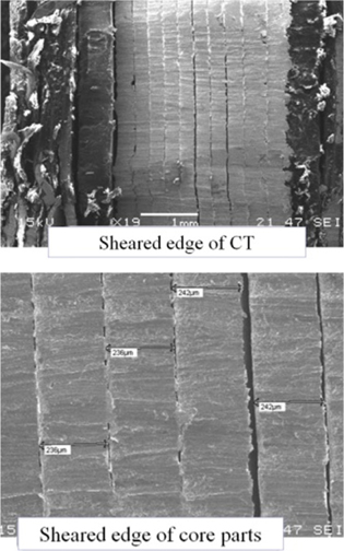
We proposed an analysis method in which the designed CT has an air gap in a ferromagnetic material core to decrease the generated magnetic flux. Inserting the air gap in the magnetic path increases the total magnetic reluctance against the same magnetic motive force (MMF). Using a different ferromagnetic material core to that of steel also induces the generation of low/high magnetic flux. These features can protect the magnetic saturation of the CT core compared with the standard steel core. Also, the proposed CT was tested with various magnetic hysteresis curves for the CT core, whereby each core has a different air gap length along the core to expand the range of measurement. Fig. 1 shows the sheared edges of the CT, which are composed of several layers.
2. ALALYSIS OF TIME HARMONIC FIELD
In two-dimensional analysis using magnetic vector potentials, the governing equations of the eddy current problem are derived from Maxwell’s equations, neglecting the displacement current. The secondary current of CTs is generated by the AC source of the primary circuit. When the source current is time-harmonic, the governing system equation is expressed as:
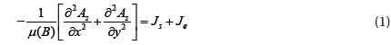
where B is the magnetic flux density, μ is the permeability of the region, Az is the magnetic vector potential, and Js and Je are the source current density and the eddy current density, respectively. The material of the core is isotropic and the magnetic saturation phenomena are considered using a hysteresis curve. When a conductive media exists in the time-varying magnetic field, the eddy current is induced in the conductor. In addition, a relationship between eddy current and conductivity is as follow.

where σ denotes the electric conductivity, E denotes the electric felid intensity, and for the eddy current problem, (1) is rewritten as follows.
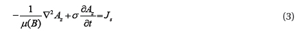
Assuming that all physical quantities of the magnetic fields have sinusoidal patterns in the steady-state, the complex variable approximation shown in (4) and (5) can be applied to the time derivative term in (3).


From the computational procedure for the finite element formulation, (1) is transformed into a matrix equation as;

where,
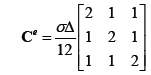
C refers to the material property, S is the matrices associated with the geometrical information, F is the forcing term including current density, and Δ is the area of the triangle mesh. Through the iterative calculation of the governing equation, the nonlinear analysis of the CT core can be performed.
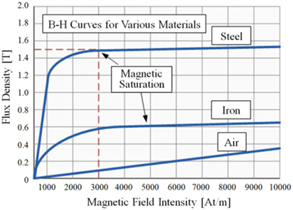
Figure 2 represents the magnetic saturation characteristics of various magnetic materials. According to the material property, the saturation point of the core can be controlled. In other words, it is possible to measure a larger primary current. It is possible to analyze the nonlinearity through the iterative calculation. Here, the cast iron delays the starting point of magnetic saturation when the primary current increases and the ferrite core can cause a low magnetic flux density level at the core.
3. INDUCED ELECTROMOTIVE FORCE
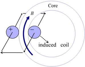
Figure 3 shows a schematic diagram to illustrate the electromotive force (EMF) of 2nd winding for the current transformer. The magnetic flux generated by the primary current being measured is also expressed by the magnetic vector potential as (8).

where B is the magnetic flux density of a single turn, A is the magnetic vector potential of the winding region, and ± refers to the direction of the induced current.
The EMF is calculated by differentiating the magnetic flux linkage with respect to time. The induced voltage of the 2nd winding is written from the differential equation of the flux linkage for the closed loop as (9).
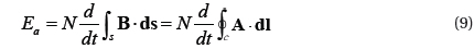
where N is the number of turns, B is the linkage flux density, and s is the area of winding. Using the Stokes’ theorem, the EMF formula is rewritten as follows.
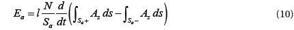
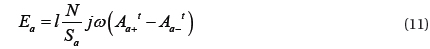
where l is the axis length of the coil, Sa+ is the positive winding area, and Sa– is the negative winding area. Finally, (10) is modified similarly to (11) using the complex variable approximation.

where Aa+t and Aa–t denote the mean values of the magnetic vector potentials at the positive and negative windings, respectively.
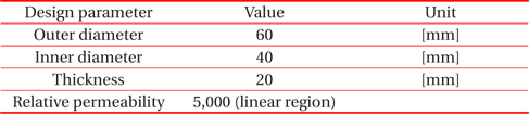
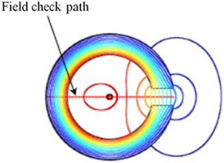
To know the characteristics of the magnetic field, the commonly used CT is adopted and primary currents are applied up to 6,000 [A]. Also, Mat. 1 in Fig. 7 is used to analyze the magnetic nonlinearity of the core. The material property is the B-H characteristics curve of stainless steel. Adding an air gap in the magnetic core means that the magnetic flux path is increased, i.e., the magnetic reluctance of the core is increased because air has a relatively low permeability. Table 1 shows the dimensions of the parameters applied in this work. The path for obtaining the magnetic flux density is shown in Fig. 4.
[Table 1.] Dimensions of design parameter for analysis model.

Dimensions of design parameter for analysis model.
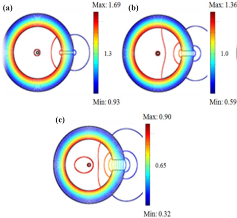
Figure 5 shows the distributions of magnetic field for the CT having an air gap in the core. The air gap lengths of 1, 2, and 4 [mm] are applied. The fringing effect with a wide air gap is larger than the small one. If there is a leakage flux in the core, the linearity of the EMF characteristics for the current transformer is not guaranteed. First, we need to know the magnetic field distribution of the core and the surrounding.. The quantitative values of magnetic flux density were calculated considering magnetic nonlinearity in accordance with variations of the air gap.
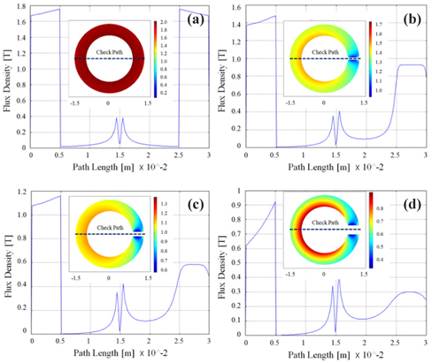
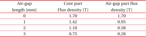
The magnetic flux densities along the field check path expressed in Fig. 4 are shown in Fig. 6 in accordance with the variation of air gap. As the size of the air gap increases, the magnitudes of magnetic flux density in the core gradually decrease from a maximum value of 1.5 to 0.75 [T]. This means that the saturation point will slow down. In other words, the primary current can be further increased. The magnitudes of flux densities in the air gap part were too small and became flat. Finally, the CT with an air gap can be used to measure the large current of the primary circuit. The average magnetic flux density according to air gap size is shown in Table 2.
[Table 2.] Mean values of the flux density at the core and air gap parts.

Mean values of the flux density at the core and air gap parts.
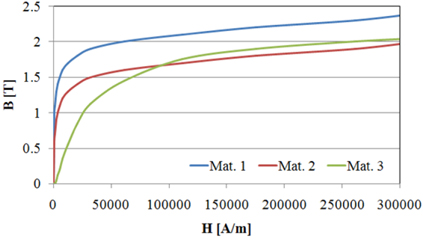
Many ferromagnetic materials are used in current transformers and are selected based on their purpose and use. Fig. 7 shows the magnetic hysteresis curves of three types of materials named Mat. 1, Mat. 2, and Mat. 3. Mat. 1 is stainless steel used in cookware, cutlery, household hardware, surgical instruments, and as an automotive and aerospace structural alloy and construction material in large buildings. It has relatively large magnetic permeability compared to other magnetic materials. Mat. 2 is the magnetic characteristics of cast iron used in cookware, industrial devices, and electrical machines. Mat. 3 is artificial materials used to investigate the characteristics of the electromotive force of secondary coils of types such as CMD ferrite. This is used in broadband transformers and its maximum relative permeability is usually less than 10,000. In Mat. 2, the magnitude of magnetic saturation is decreased and Mat. 3 has an increased linear region compared with the reference material in the beginning stage of the curve.
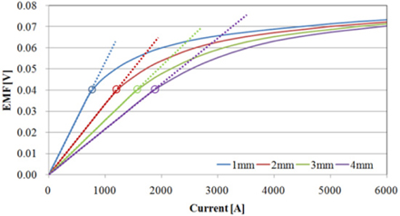
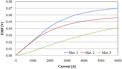
Figure 8 shows the EMF characteristics of the secondary coil when the air gap length of the core is changed through a range of four steps. As the size of the air gap increases, the saturation point moves further towards the large primary current. Interestingly, the EMF values are the same for all cases. The results of the EMF characteristics of the secondary coil when changing the magnetic hysteresis are shown in Fig. 9. The EMF values were smaller for Mat. 2. Also, in the case of Mat. 3, the linear region was wider and the EMF values were lower than those of the reference material. With a good combination of appropriate air gap size and magnetic hysteresis curve to suit its purpose, a current transformer that can measure a larger current can be obtained.
In order to fabricate a CT in which it is possible to measure a large current, the volume of the CT needs to be increased. However, if the space in which the CT is to be installed is not sufficient, an alternative must be suggested. This paper discusses the design of a CT with different material properties and with an air gap inserted into the CT core. An accurate magnetic field analysis is used to consider the size of the air gap and the magnetic saturation characteristics; it is also helpful to estimate the dimensions of the device for this purpose. Further studies are required on the analysis of EMF characteristics when lightning, surges, and inrush currents flow through the current transformer.


![Magnetic flux distributions of air gap CTs when the primary currents are 0 to 6,000 [A]. Lengths of air gap are (a) 1, (b) 2, and (c) 4 [mm] and magnetic reluctances are 124,602, 124,204, and 123,408 [A/ Wb], respectively.](http://oak.go.kr/repository/journal/15568/E1TEAO_2015_v16n1_37_f005.jpg)
![Magnetic flux density along the path, which is line crossing the center from the left end to the right air gap part; (a) air gap : 0 [mm], (b) air gap : 1 [mm], (c) air gap : 2 [mm] and (d) air gap : 4 [mm]. The magnitudes of magnetic flux density in the core differ according to the air gap size.](http://oak.go.kr/repository/journal/15568/E1TEAO_2015_v16n1_37_f006.jpg)

![Characteristics of electromotive force with respect to primary current according to magnetic materials (Air gap: 4 [mm]). The linear region is the largest in the case of Mat. 3. but EMF values are low compared to other materials.](http://oak.go.kr/repository/journal/15568/E1TEAO_2015_v16n1_37_f009.jpg)