A worst-case estimate of an envelope correlation coefficient (ECC) is obtained for small multiple-input multiple-output (MIMO) mobile antennas operating below 1 GHz. The worst-case estimate is numerically derived in this paper using spherical and exponential wave functions. The derived result confirms that the worst-case ECC can be easily obtained from the rotation angle between the radiation patterns of two MIMO elements, which are attained directly from the amplitude of 2D electric field patterns without any additional phase and polarization information. As a practical example, MIMO mobile antennas with different antenna element arrangements are compared to verify the validity of the proposed worst-case estimate. Moreover, based on these analyses, we also suggest an effective approach to reduce the ECC of a small MIMO mobile antenna operating below 1 GHz by properly locating the antenna elements to make the radiation patterns perpendicular to each other.
An envelope correlation coefficient (ECC) is a critical parameter in evaluating the signal correlation of a multiple-input multiple-output (MIMO) antenna [1-3]. According to a standard definition, the ECC value should be calculated using the complicated amplitude, phase, and polarization information obtained from the 3D radiation patterns of a MIMO antenna [4]. However, obtaining the required information is both timeconsuming and expensive due to the use of specialized equipment and facilities, which might not be available to every researcher.
To solve this problem, based on the relationship between the antenna patterns and scattering parameters [5], several researchers have tried to simplify the process of calculating the ECC using S-parameters, instead of the 3D radiation patterns [6-8]. This simplified method has been widely used to evaluate the performances of mobile MIMO antennas [9-11]. However, the ECC calculated using the equation in [6] is much lower than the actual value when the targeted small MIMO mobile antenna operates in a low-frequency range, typically below 1 GHz, because the antenna elements have low efficiency, and a large portion of the energy is radiated from the ground plane [12]. The worst-case estimates of the ECC using the S-parameters provided by [7,8] were both too conservative, and they could even be larger than one in some cases.
Therefore, we consider another direction and propose a method that uses the rotation angle, which can be simply obtained using the amplitudes of 2D electric field patterns, to generally estimate the worst-case (upper bound) ECC of a small MIMO mobile antenna operating below 1 GHz. The first part of this paper presents a simple general expression for the targeted worst-case estimate of the ECC through a direct derivation using the spherical and exponential wave functions. Then, the correctness of this worst-case estimate is verified by comparing MIMO mobile antennas that operate at 0.8 GHz and under different arrangements of the antenna elements. Moreover, by investigating the different factors (rotation angle, translation of phase centers, and occasional pattern variance) related to the ECC, we prove the rotation angle, which is chosen to estimate the worst-case ECC, is also an effective applicable factor to reduce the ECC for a MIMO mobile antenna below 1 GHz. A low ECC can be attained when the rotation angle of a MIMO mobile antenna approaches 90° by locating two antenna elements on the perpendicular edges of the ground plane.
II. WORST - CASE ESTIMATE OF ECC
In this paper, we assume the antennas are operating in an isotopic/uniform multi-path condition (XPR = 1 and
Based on the above assumption, the ECC (
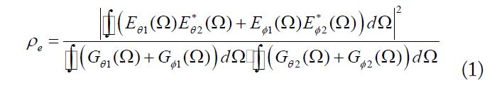
where
Meanwhile, we note the diversity and corresponding ECC are mainly determined by three factors (rotation angle, translation of phase centers, and occasional pattern variance) in MIMO antennas. Thus, our investigation of the worst-case ECC will start by exploring and comparing these three factors.
In addition, we analyze and optimize the antenna performance using the commercial computer-aided design software package Ansoft High Frequency Structure Simulator (HFSS) ver. 13.0 (ANSYS Inc., Canonsburg, PA, USA) throughout this paper.
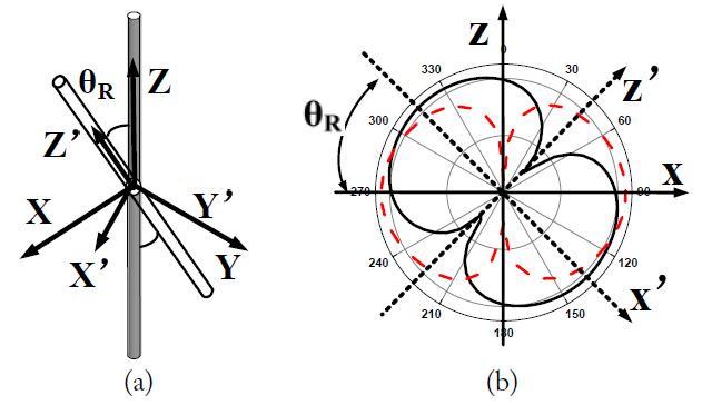
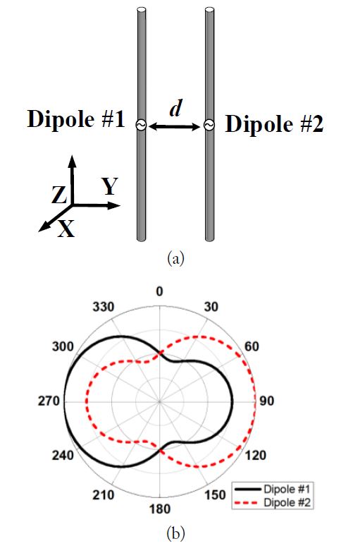
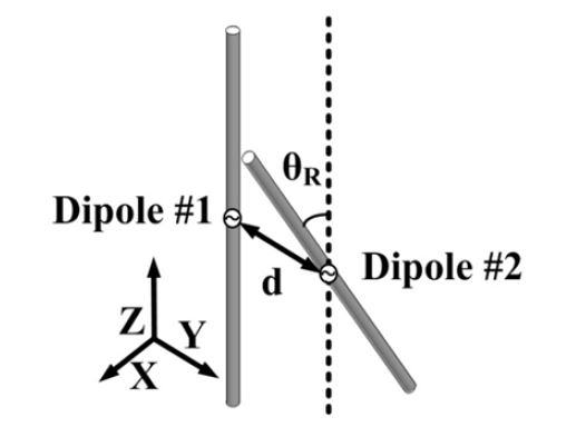
As mentioned earlier, a mobile antenna element operating below 1 GHz typically has a quasi-omnidirectional (doughnut shape) radiation pattern. To investigate the relationship between the rotation angle and the ECC, we first explore a simple dual-dipole MIMO system, which can produce standard omnidirectional radiation patterns.
Fig. 1(a) shows the geometry of a dual-dipole MIMO system with one antenna element with a two dipoles, which are also the equivalent phase centers, are both located at the origin of the coordinate. We also assume that the radiation pattern of one dipole is not affected by the other dipole; thus, no occasional pattern variance occurs. During our investigation, one dipole points along the z-axis, and the other dipole rotates around the y-axis at
The modified electric field intensity from a dipole antenna can be expanded into spherical wave functions [16,17] as

where

is the simplified second-order spherical wave function with a large argument approximation [18].
The Euler angle is used to describe the
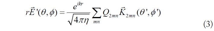
The relationship between the electric field intensities in the primed and unprimed coordinate systems can be expressed using an integral equation
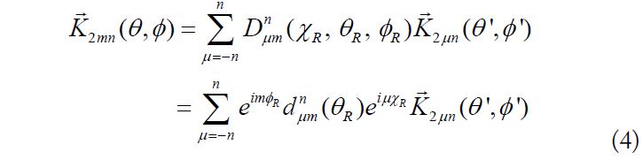
where the angles
Then, the ECC value can be calculated using Eqs. (1)–(4).
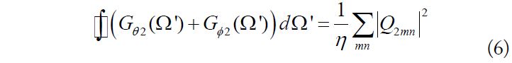
In Eq. (1), the first and second terms in the denominator can be individually calculated using Eqs. (2) and (3). The calculation can be simplified owing to the orthogonality of the spherical far-field pattern functions [16]. Finally, we can obtain


We would not be surprised to find that the first and second terms of the denominator have the same value because the radiation patterns from these two dipoles are the same except for the rotation angle. In addition, the results from Eqs. (5) and (6) are only related to the total radiated power of the radiation patterns and are independent of the rotation of the radiation patterns.
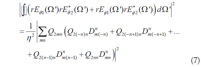
The numerator in Eq. (1) can also be calculated. This time, the two electric field intensities of the different antenna elements should be integrated into the same coordinate system. Thus, the electric field intensity from the dipole along the z-axis determined using Eq. (2) is transferred from the unprimed coordinate system to the primed coordinate system using Eq. (4).
Then, the integration of the numerator into Eq. (1) is carried out in the primed coordinate system as
The ECC of a dual-antenna MIMO system can be calculated using Eqs. (5)–(7). For example, when
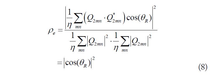
Considering the dual-dipole MIMO antenna shown in Fig. 1, the dipole pointing along the z-axis corresponds to the condition where
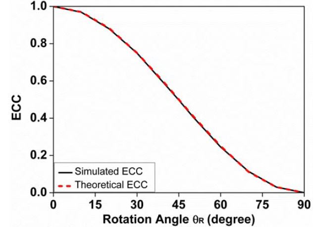
In this case, the ECC of the dual-dipole MIMO antenna shown in Fig. 1 can be simply expressed as

where
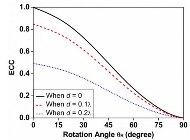
The above theoretically calculated ECC value is compared with the simulated value in the HFSS, and the result is shown in Fig. 2. The theoretical value of the ECC matches the simulated value well, and Eq. (8) is proven correct. The ECC of the ideal dipole MIMO system in Fig. 1 is accurately evaluated using Eq. (8) by the rotation angle, which can be directly observed from the amplitude of the 2D electric field patterns.
2. Translation of Phase Centers
Aside from the rotation angle, the translation of the phase centers of the different antenna elements can also reduce the ECC.
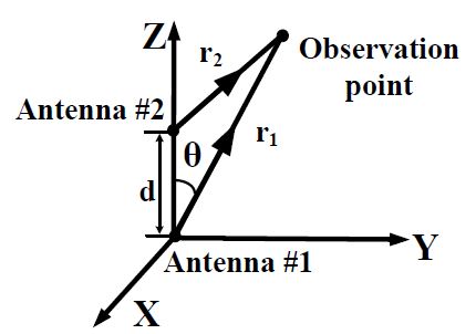
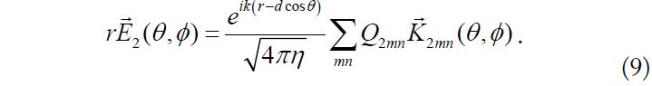
Let us assume the MIMO antenna system under investigation is an array of two same-directional infinitesimal dipoles positioned along the z-axis at 0.8 GHz, as shown in Fig. 3. The equivalent phase center of antenna element #1 is placed at the origin, and that of antenna element #2 is placed on the positive z-axis. We also assume the radiation pattern from one dipole is still unaffected by the other dipole. Then, the electric field intensity

from antenna element #1 can be expressed using Eq. (2). The electric field intensity from antenna element #2 is modified from Eq. (2) with a large approximation as
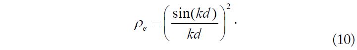
The ECC in Eq. (1) can be calculated using Eqs. (2) and (9). When

When
Then, the ECC can be expressed as

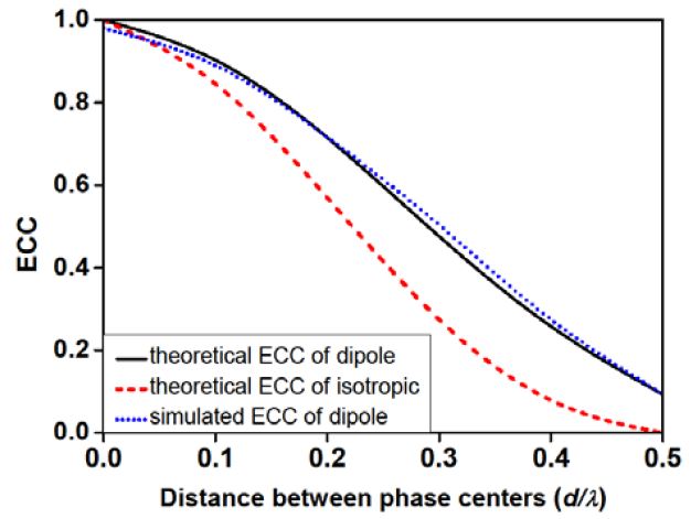
The above calculated theoretical ECC value is compared with the simulated value in the HFSS, as shown in Fig. 4. The theoretical ECC of the MIMO antenna with isotropic elements in Eq. (10) is observed to be lower than that of the MIMO antenna with dipole elements in Eq. (11) when the distance between the phase centers is the same. Meanwhile, the simulated ECC value with dipole elements again matches well the theoretical value, which also proves the increase in the translation of phase centers of the different antenna elements reduces the ECC.
3. Occasional Pattern Variance
In the above analysis, we assume the radiation patterns from the different antenna elements have the same shape except for the rotation angle or the translation of phase centers. However, in a real situation, the radiation pattern from one antenna element is affected by the other antenna element and surrounding metal hardware, which cause occasional pattern variances. For example, we assume a dual-dipole MIMO system with both dipoles is pointing toward the z-axis and positioned side by side along the y-axis. Fig. 5(a) shows the geometry of the mentioned dual-dipole MIMO system positioned side by side along the yaxis, which operates at 0.8 GHz. The corresponding radiation patterns of this MIMO system are plotted in the xy-plane at 0.8 GHz, as shown in Fig. 5(b), which shows the occasional pattern variance caused by the reflection in the other antenna element changes the shapes of the radiation patterns.
To investigate the effect of occasional pattern variances on ECC performance, we assume two exactly similar antenna elements have the same radiation patterns without any rotation and translation of phase centers. The electric field intensities of these two antenna elements are defined using Eq. (2) as

and

respectively. Now, we assume only a few (one or more) wave coefficients Q

change because of the occasional pattern variance caused by the reflection of the surrounding metals. According to the CauchySchwarz inequality theory, the ECC of this MIMO system will be less than one.
As a result, the occasional pattern variance will also reduce the ECC. However, we should note that, in contrast to the rotation angle and translation of phase centers, the relationship between the occasional pattern variance and the ECC value cannot be determined by a simple parameter because the occasional pattern variance is mainly determined by the parameters of the surrounding metal elements, which are complex and not unique.
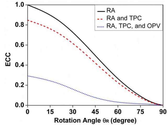
In the previous sections, we have shown that the rotation angle, translation of phase centers, and occasional pattern variance can individually reduce the ECC of a MIMO antenna. In the next parts, we will present a comprehensive analysis of these three factors. To perform the analysis, we assume a dual-dipole MIMO system where the phase centers of the dipoles are located side by side along the y-axis. Dipole #1 points toward the z-axis and dipole #2 rotates with
Under the assumption only the rotation angle and translation of phase centers are considered, the ECCs of the dual-dipole MIMO antenna with respect to the variation in
Furthermore, the ECCs of the dual-dipole MIMO antenna with respect to the variation in
According to the results shown above, the final ECC value is lower than the ECC value calculated using only the rotation angle. Therefore, the ECC given by Eq. (8), which only considers the rotation angle, would be the worst-case estimate of the ECC.
5.Investigation of a Real MIMO Mobile Antenna
The above investigation was only performed for ideal dual-dipole MIMO antenna systems. To confirm the validity and effectiveness of the worst-case estimate using rotation angle, three MIMO mobile antennas with different arrangements of the antenna elements operating at 0.8 GHz are analyzed next.
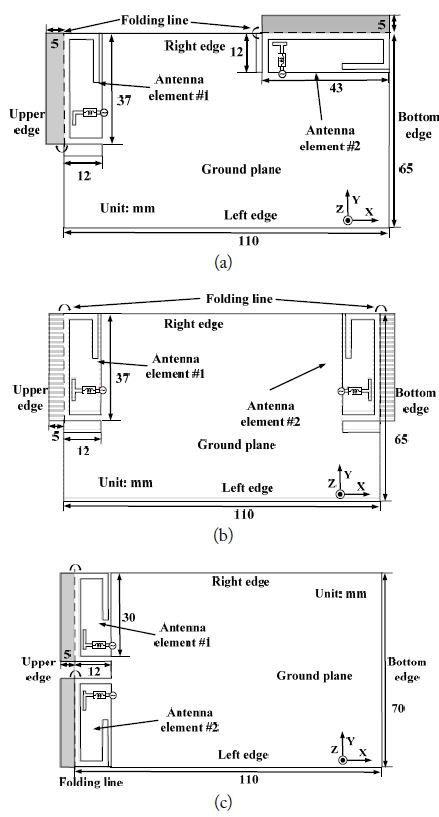
Fig. 9 shows the geometries of these three MIMO mobile antennas. Fig. 9(a) shows a MIMO mobile antenna under arrangement #1 (the antenna elements are perpendicular to the upper and right edges). The proposed MIMO mobile antenna shown in Fig. 9(a) consists of two compact wideband inverted F-antenna elements operating around 0.8 GHz. In the same manner, Fig. 9(b) shows a MIMO mobile antenna under arrangement #2 (the antenna elements are opposite the upper and bottom edges). Fig. 9(c) shows a MIMO mobile antenna under arrangement #3 (the antenna elements are both at the upper edges).
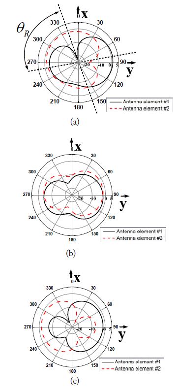
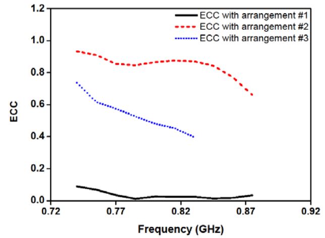
The corresponding radiation patterns in the xy-plane at 0.8 GHz are compared, as shown in Fig. 10. Fig. 10(a) shows the radiation patterns from the MIMO mobile antenna under arrangement #1, Fig. 10(b) shows those under arrangement #2, and Fig. 10(c) shows those under arrangement #3. Furthermore, the ECCs of these three MIMO mobile antennas from the simulated 3D radiation patterns over the entire operational frequency band are compared, as shown in Fig. 11.
The ECC of the MIMO mobile antenna under arrangement #1, whose geometry is shown in Fig. 9(a), is mainly affected by the rotation angle. The relevant radiation patterns are shown in Fig. 10(a). The rotation angle
The ECC of the MIMO mobile antenna under arrangement #2, as shown in Fig. 9(b), is mainly determined by the distance between the phase centers of the different antenna elements. Fig. 10(b) shows that
The ECC of the MIMO mobile antenna under arrangement #3, as shown in Fig. 9(c), is mainly determined by the occasional pattern variance caused by the reflection in the other antenna element and the surrounding ground planes, as shown Fig. 10(c). As a result, a corresponding ECC of approximately 0.5 is obtained from the 3D spherical radiation patterns at 0.8 GHz. Fig. 11 shows the MIMO antenna under arrangement #3 has a bad ECC of greater than 0.4 over the entire operational frequency band, which is mainly affected by the occasional pattern variance.
The three practical MIMO mobile antennas with different arrangements previously discussed can represent most of the recently published MIMO mobile antennas. We should note the final ECC value is commonly lower than the ECC value calculated using only one these three factors (rotation angle, translation of phase centers, and occasional pattern variance). Actually, all three factors can potentially cause the worst-case estimate of the ECC.
However, the distance between the phase centers of the different antenna elements in a small MIMO mobile antenna is much smaller than the physical distance described above. Therefore, the translation of phase centers cannot effectively reduce the ECC of a MIMO mobile antenna and is unsuitable for the targeted worst-case estimate, because the positions of the phase centers cannot be directly observed from the radiation patterns.
Meanwhile, the occasional pattern variance is difficult to numerically evaluate and must be calculated with the 3D radiation patterns using all amplitude, phase, and polarization information. Therefore, it is still not a suitable choice.
On the other hand, the rotation angle is the only parameter that could be directly obtained using the amplitude of 2D electric field patterns without any additional phase and polarization information. Further, the relationship between the ECC and rotation angle can be very simply obtained using Eq. (8) as long as the antenna elements in a MIMO system have quasi-omnidirectional (doughnut shape) radiation patterns. Therefore, the rotation angle becomes the best choice, and we finally choose it as the parameter to estimate the worst-case ECC of a MIMO mobile antenna below 1 GHz.
Moreover, Fig. 11 shows the ECC of the MIMO mobile antenna under arrangement #1, which is mainly affected by the rotation angle, is obviously lower than those of the MIMO mobile antennas under arrangements #2 and #3, which are mainly affected by the translation of phase centers and occasional pattern variance. According to this analysis, we can state that, compared with the translation of phase centers and occasional pattern variance, the rotation angle is a more effective applicable factor in reducing the ECC of a MIMO mobile antenna below 1 GHz. A low ECC would be achieved when the rotation angle of a MIMO mobile antenna approaches 90° by locating the two antenna elements perpendicular to the edges of the ground plane, which can be guaranteed as the method for the worst-case estimate of the ECC with rotation angle introduced earlier.
This paper has presented a method of utilizing the rotation angle to estimate the worst-case ECC of a small MIMO mobile antenna with an operational frequency below 1 GHz. This method aims to simplify the measurement process, reduce the measurement cost, and develop a simple but effective approach to reduce the ECCs of mobile MIMO antennas below 1 GHz. The method is directly derived using the spherical and exponential wave functions. The result shows the worst-case estimate, which is evaluated using rotation angle, could be easily achieved using the amplitude of 2D electric field patterns without any additional phase and polarization information. As a practical example, a MIMO mobile antenna operating at around 0.8 GHz was investigated. It confirmed the rotation angle could be a good choice in estimating the ECC of a small MIMO mobile antenna. The value of the ECC can be optimized when the rotation angle is adjusted to be almost 90°.