A traditional cell covers an area with a radius of up to several kilometers. However, due to the growing demand for higher data rates, this cell radius is becoming much smaller to enable increases in system capacity and provide higher spatial reuse. However, a denser cellular deployment can cause severe intercell interference among neighboring cells that use the same frequency band. To address this problem, researchers have focused their attention on an intercell interference coordination (ICIC) scheme.
The key purpose of the ICIC scheme is to differentiate the transmission power level of each frequency subband depending on user location. Users at the edge of a cell are allocated frequency subbands with a higher transmission power level that is orthogonal for the neighboring cells, while users at the center of the cell can be served on low-power frequency subbands since they have better signal power and reduced interference from neighboring cells.
Three types of ICIC schemes have been presented in previous studies [1]. The first is static ICIC, which is also known as fractional frequency reuse (FFR) [2,3]. This scheme has a fixed cell center and cell edge subbands, and the resource partitioning does not change. The second scheme is called dynamic ICIC [4,5]. This scheme instantly adapts its subband partitioning to network conditions. It does not require prior frequency planning, but it does demand a huge amount of information exchange between neighboring cells. The third scheme is known as semi-static ICIC [6,7]. It operates at a centralized node in a centralized manner and entails a lot of information exchange. In this paper, a resource-partitioning algorithm categorized into a semi-static ICIC is proposed. The key feature of the proposed scheme is that it does not need a centralized node and operates in a distributed manner. It also reduces in-formation exchange between adjacent cells.
The rest of this paper is organized as follows. Section II presents the system model for the design of the proposed algorithm. Section III proposes a distributed resource-partitioning algorithm. Section IV provides the numerical simulation results, and the paper is concluded in Section V.
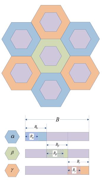
In this study, we considered the orthogonal frequency division multiple access (OFDMA) downlink transmission in multicellular networks. Each base station (BS) and user was equipped with an omnidirectional single antenna located at the center of the cell, and each user was connected to a single BS (the terms ‘BS’ and ‘cell’ are used interchangeably throughout this paper). We assumed that BSs can exchange information with surrounding BSs through a wired backhaul connection. In this paper, we use the following notations: the set of users connected to BS-
III. RESOURCE PARTITIONING SCHEME
To apply ICIC schemes, users need to be classified as either cell center or cell edge users. To do this, we used reference signal received power (RSRP) in a long-term evolution (LTE) system because it can be measured from both a serving BS and neighboring BSs. We denoted RSRP at user-
Using the RSRP values, we defined the interference factor (IF). The IF from neighbor BS-

The IF at user-

Using the above IF and a predefined threshold value (

In the same way, the set of cell edge users connected to the serving BS-
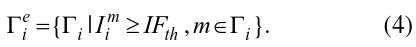
For the proposed algorithm, we needed to subdivide the set of cell edge users. Therefore, we defined the set of cell edge users connected to serving BS-

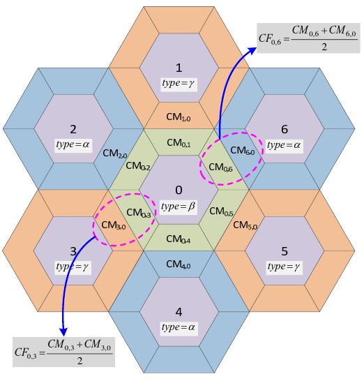
In general, user distributions among cells are not homogeneous. There may be overloaded or underloaded cells. Moreover, within a cell, there may be uneven distributions of users in the cell center and cell edge regions. In such cases, the impact of the interference between adjacent BSs is dependent on the distributions of users and the traffic load. Here, we present a new metric that can measure the impact of interference from neighboring BSs. To do this, we define the coupling metric (CM) and coupling factor (CF), which is a combination of the IF defined above and the user’s traffic load. If
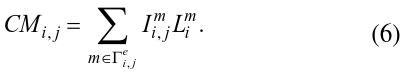
The CF is defined as the average value of the CM between two BSs:

The CF means that adjacent cells interfere with each other via two factors, power from other cells and users’ own traffic from serving cells. In a seven-cell deployment, the CM and CF can be calculated as shown in Fig. 2.
Considering the system model in Fig. 1 and an inhomogeneity in user distribution, in the underloaded state, the cell in an overloaded state needs more cell edge subband from neighboring cells. By assuming that cell 0 in Fig. 2 is in an overloaded state and its neighboring cells are in underloaded state, we can explain the procedure to obtain the available cell edge subband at cell 0. Let

be the unused cell edge subband of cell
In the same way, the available cell edge subband obtained from cell type
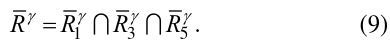
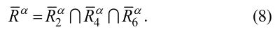
The resulting cell edge subband of cell 0 is a summation of the available cell edge subband from cell type
According to this description,

is determined by the smallest unused cell edge subband among cell type


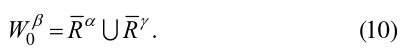
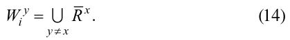
Using (11) and (12), we can denote the available cell edge subband obtained from cell type

which is the relaxed expression of (8) or (9). In addition, (10) can be rewritten in more general expression as
A lower CF threshold value means that resource conflicts in the cell edge subband are not allowed; thus, the interference between neighboring cells is decreased at the cost of resource utilization. In contrast, a higher CF threshold value implies a higher probability of resource overlapping between neighboring cells for high resource utilization.
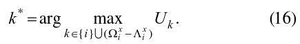
Although all the cells in a network can calculate the available cell edge subband, they cannot use those resources at the same time. This therefore leads to the problem of determining which cell should use the available cell edge subband. To resolve this dilemma, we propose the following resource allocation scheme, which we refer to as a cell-scheduling scheme.
Let
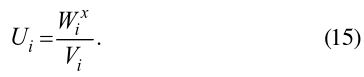
All the cells in the network calculate their own utility value as described above and compare it with the utility values of the adjacent cells. If its own utility value is the highest one, then the cell uses the available cell edge subband in the next time period. From the utility function (15) and expressions (11) and (12), we can describe the selected cell index
5. Information Exchange between Cells
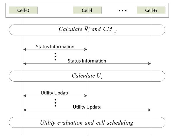
The proposed algorithm described above needs to share information among the 1-tier cells. To do this, we assume that all the 1-tier cells are connected through a high-speed wired link, such as an X2 interface, in an LTE system. To calculate the CF value between two cells, the cells need to share their CM and unused cell edge subband

with each other. The calculated utility values also need to be shared within all the 1-tier cells. Therefore, this information exchange consists of two stages (shown in Fig. 3).
From the viewpoint of information exchange, each cell only needs to share information with the adjacent cells surrounding it. This means that each cell can simply decide to use the available cell edge subband in a distributed manner with a two-stage information exchange process.
To simulate this scenario, we considered a system of 19 hexagonal cells, each with a radius of 1,000 m. Table 1 shows the parameters used in the simulation. We used the central cell technique developed by [8]; that is, the simulation results were collected only in the central cells of the simulated multicell layout for a more accurate evaluation. To conduct a performance comparison using the proposed algorithm, we used the Reuse-1 and static FFR as the reference schemes. The Reuse-1 scheme randomly assigns physical resource blocks (PRB) to different users with equal power and bandwidths irrespective of their category. For a static FFR scheme, we fixed the cell edge subbands at each cell and allocated the cell edge users to these subbands with higher priority. In contrast to the proposed scheme, there was no overlapping or conflict of the cell edge subbands between adjacent cells.
[Table 1.] Simulation parameters
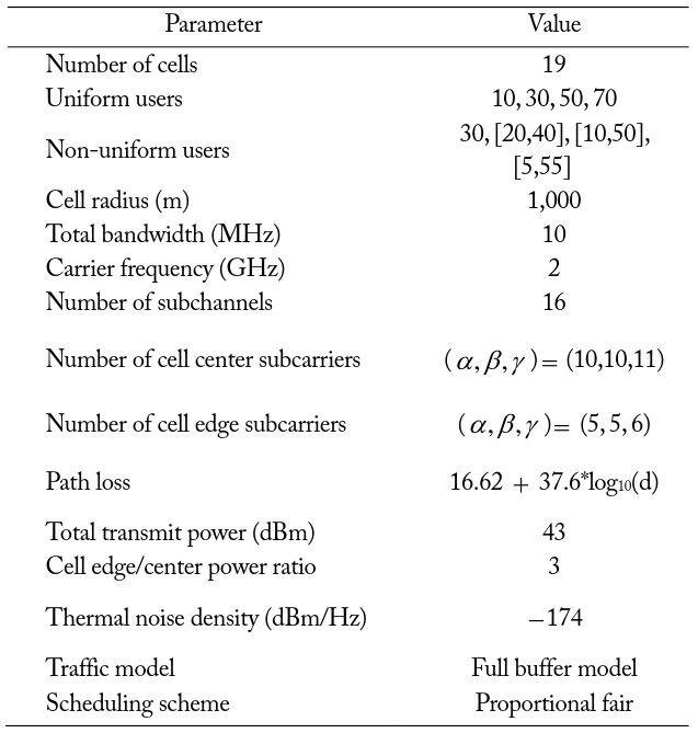
Simulation parameters
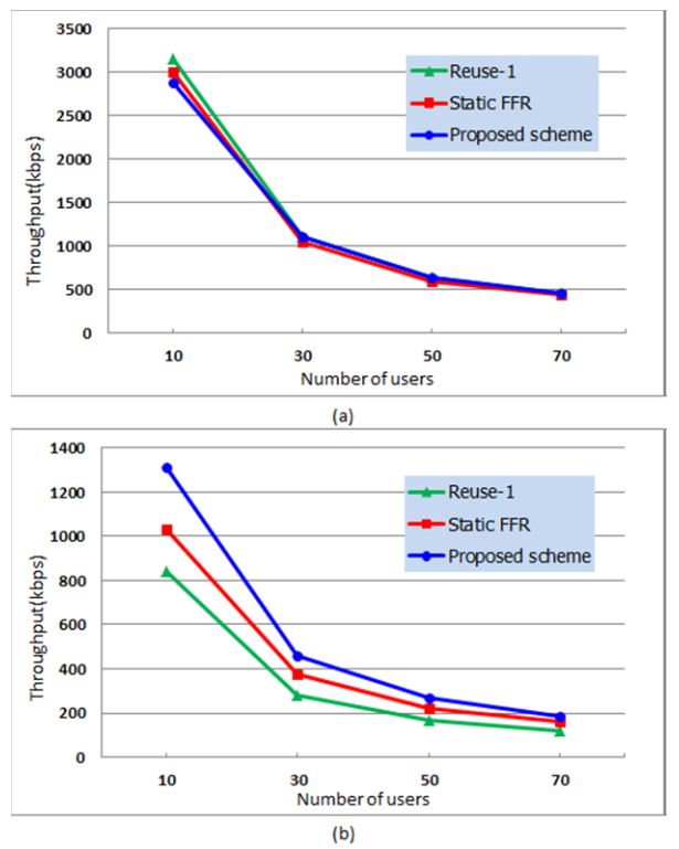
There are two types of user distributions, uniform and nonuniform. In a uniform distribution, each cell has the same number of users that are uniformly distributed within the cell. In a non-uniform distribution, the number of users varies from 10 to 70. ICIC schemes generally use a resource-partitioning method to enhance the cell edge performance at the cost of average user throughput. The goal of our scheme was to improve the cell edge user throughput with a minimal degradation of the average user throughput. We therefore evaluated both the average user throughput and the cell edge user throughput.
Fig. 4 shows the average user throughput versus the number of users per cell and the cell edge user throughput versus the number of users per cell in a uniform user distribution. It can be noted that the proposed scheme significantly improves the cell edge user throughput (50% to 60% more than the Reuse-1 scheme) and only slightly degrades the average user throughput (less than 10% compared with Reuse-1). As the number of users increases, the amount of unused subband in neighboring cells decreases and the performance of the three schemes becomes more similar as shown in Fig. 4(b).
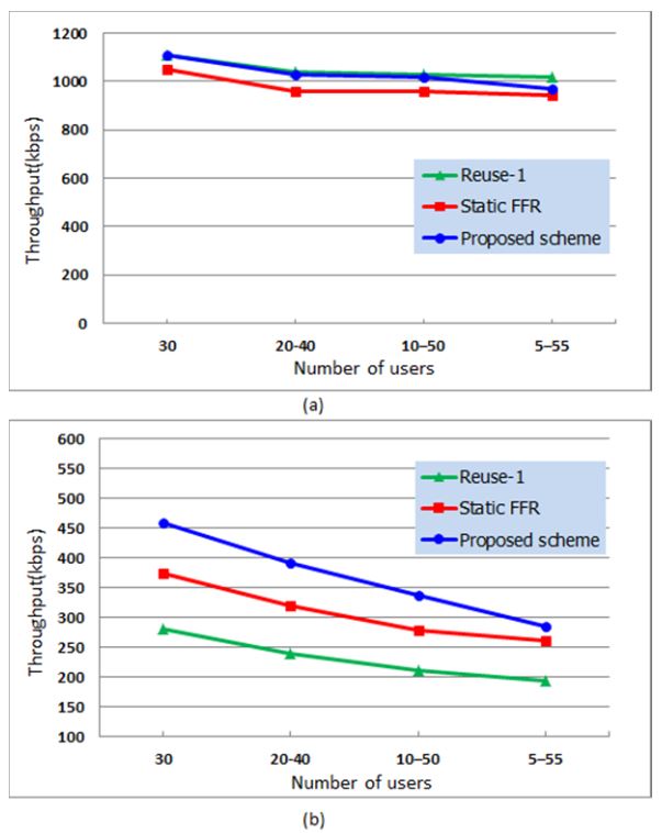
Fig. 5 shows the average user throughput versus the number of users per cell and the cell edge user throughput versus the number of users per cell in a non-uniform user distribution. In this scenario, we maintained the average number of users per cell as 30. As the inhomogeneity of user distribution increases, all performance metrics decrease. However, our proposed scheme has the highest cell edge user performance regardless of user distribution.
In this paper, we have proposed a new resource-partitioning scheme with ICIC for multicellular networks. The proposed scheme enables improved cell edge throughput performance with only a slight degradation in average user throughput performance compared with the Reuse-1 and static FFR schemes. Our proposed scheme is based on the utilization of the cell edge subband from adjacent cells in an underloaded state. To further improve the performance of the cell edge user throughput and to increase resource utilization, we have presented the idea of using a CF between adjacent cells as it leads to a performance trade-off between the cell edge and cell center zones. The key feature of the proposed scheme is that it is performed at each base station in a fully distributed manner and that there is no need for a central functional entity. Each cell solves its own resource allocation problem with minimal information exchange between adjacent cells. The simulation results show the effectiveness of our scheme under various scenarios.