In this paper, a novel monopole antenna for WLAN/WiMAX application is presented. The proposed antenna consists of two arc-shaped strips, a vertical strip, and a slot in the ground plane. In this study, a prototype of the proposed triple-band antenna was designed, fabricated, and tested. The quantitative and experimental results demonstrate that the proposed antenna satisfy the -10 dB impedance bandwidth requirement of 440 MHz for 2.4/2.5 GHz bands (from 2.26 to 2.70 GHz), 970 MHz for 3.5 GHz bands (from 3.27 to 4.24 GHz), and 870 MHz for the GHz bands (from 5.08 to 5.95 GHz), while simultaneously covering the WLAN and WiMAX bands. In addition, the presented triple-band antenna has an omnidirectional radiation pattern at all three frequency bands with an antenna gain of 4.45 dBi for the lowest band, 2.04 dBi for the middle band, and 3.98 dBi for the highest band.
There is an ongoing rapid growth of wireless communications due to the high demand for broadband service and transmission speed capacities that better support multimedia, image, and video/audio data. Wireless Local Area Network (WLAN) technology is one of the most successful and fastest-growing wireless communications technologies in the world today. The antenna is a key component of the access point for WLAN communications; thus, as WLAN communications grow in popularity, there is an increasing the need for a WLAN antenna that is low-profile, lightweight, flush-mounted, and has a simple structure. In addition, the need for a new technology that can be used when no communication infrastructure is in place has been a main concern in the past few years. Worldwide Interoperability of Microwave Access (WiMAX) has been used to provide mobile broadband Internet services with large coverage areas in many countries [1,2]. WiMAX is capable of extending Internet access coverage up to 40 km for IEEE 802.11d fixed WiMAX and up to 3 km for IEEE 802.11e mobile WiMAX. WLAN and WiMAX complement each other perfectly. This, WLAN/WiMAX synergy allows both wireless technologies to be integrated in notebooks and mobile devices, among others. However, for its short- and long-range application in modern wireless communication systems, multiband and broadband antennas that meet both WiMAX and WLAN standards are needed. A variety of antenna designs for WLAN/WiMAX band operation have been proposed [3-18]. Among these, the printed monopole antennas have been founded to be important because they have a simple structure and a low profile. In particular, the arc-shaped monopole antenna [4,14,19,20] and a monopole antenna with claw-shaped [4] and circular arc-shaped strips [14] for WLAN/WiMAX application have been studied. The clawshaped monopole antenna [4] is fabricated on a substrate with a relative permittivity of 4.4. However, the volume of this antenna is much bigger than the volume considered in this paper. On the other hand, the monopole antenna with circular arc-shaped strips, whose whole geometry resembles an ‘-ear-’ type, [14] is fabricated on a substrate with a relative permittivity of 2.65. This antenna is made of more expensive materials in comparison with conventional FR4 materials. In addition, a monopole antenna with two arc-shaped strip [19] and with a nipped stub and DGS and a broadband arc-shaped monopole antenna [20] have been proposed.
In this study, a novel monopole antenna with two arc-shaped strips, a vertical strip, and a slot in the ground plane for WLAN and WiMAX band applications was designed. A parametric study was conducted on the proposed antenna to determine the required operational frequency bands. Compared with the antennas that have already been reported, this constructed antenna has a simpler structure. It was fabricated using a conventional FR4 material that is often used to make printed circuit boards. The antenna can also provide good dual-broadband bandwidth capabilities and suitable radiation characteristics for two multiband wireless communication systems.
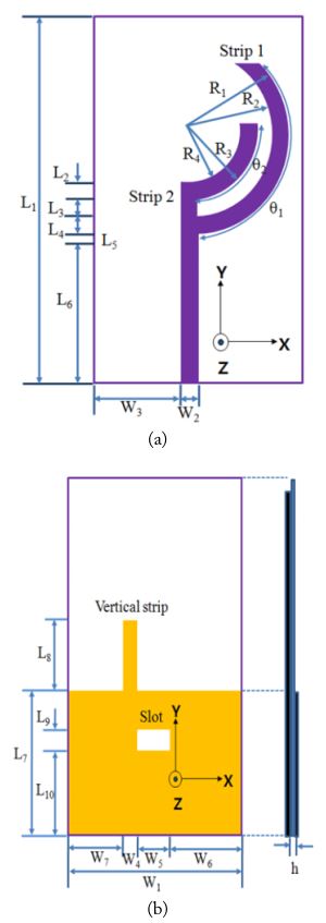
Fig. 1 illustrates the proposed configuration of the WLAN/WiMAX antenna, which is printed on the substrate surface with relative dielectric constant, loss tangent, and thickness values of 4.4, 0.002, and 1.0 mm, respectively. The total sizes of the substrate and the ground plane of the proposed antenna used in this study were 25.0 × 37.0 mm2 (
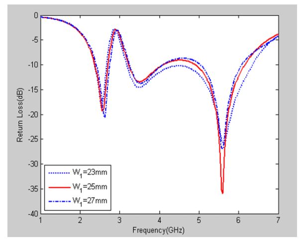
Fig. 2 illustrates the return loss for the different values of the ground plane. It can be seen that the impedance bandwidth and characteristics of the return loss did not change significantly when
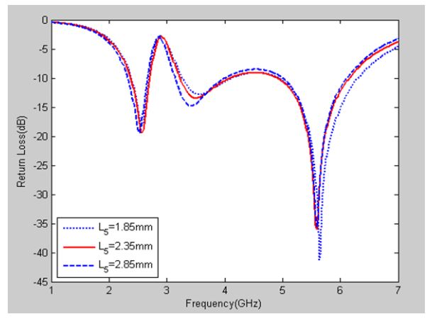
Fig. 3 illustrates the return loss for the different values of the gap (
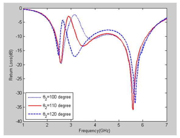
Fig. 5 shows the effect of varying strip 2 on the return loss characteristics. It can be seen here that the impedance band-width and the characteristics of the return loss were changed in the 3.5 GHz bands and not changed in the 2.4/2.5 GHz and 5 GHz bands when
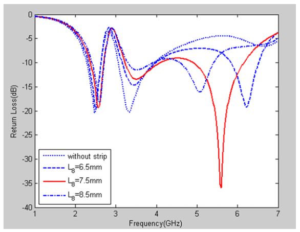
Fig. 6 illustrates the return loss of the antenna with and without the vertical strip in the ground plane. It can be seen here that the resonant frequency was not generated in the 5 GHz band when there was no vertical strip in the ground plane. The vertical strip in the ground plane was employed to generate the third resonant mode at the 5 GHz WiMAX band. This implies that the length of the vertical strip in the ground plane was greatly affected by the characteristics of the return loss in the 5 GHz band. Thus, the length of the vertical strip was taken into account when determining the proper parameters for the proposed design to achieve the 5 GHz operating band. It can also be seen Fig. 6 that the impedance bandwidth and characteristics of the return loss did not change when
Fig. 7 illustrates the return loss for the different values of the vertical strip position. It can be seen here that the impedance bandwidth and the characteristics of the return loss did not change when
[Fig. 8.] Simulated return loss of the proposed antenna with and without a slot in the ground plane.
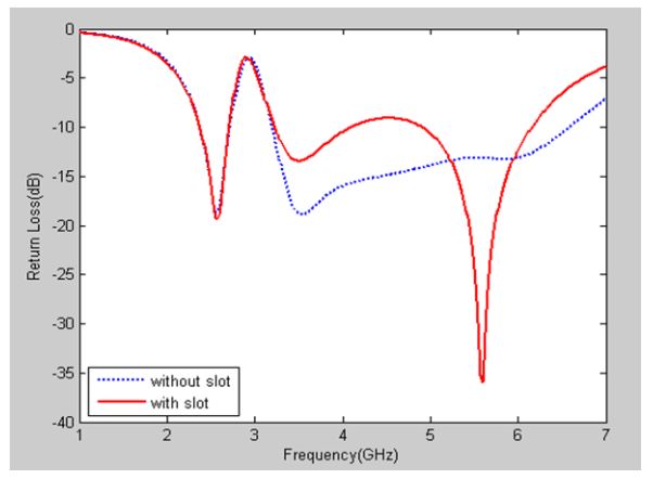
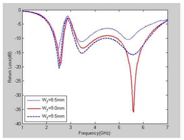
Fig. 8 shows the return loss with and without a rectangular slot in the ground plane. It can be seen here that the return loss had wideband characteristics without the rectangular slot in the ground plane and characteristics of return loss in the triple band with the required operation frequency when the rectangular slot was present. These results indicate that the return loss of the 3.5 GHz and 5 GHz bands in the proposed antenna depends heavily on the rectangular slot in the ground plane. Certainly, with the variation in the width and length of the rectangular slot in the ground plane, the return loss can be maintained at less than - 10 dB. This covers the frequency bandwidths for WLAN (2.4 - 2.484, 5.15 - 5.35, and 5.75 - 5.85 GHz) and WiMAX (2.5 - 2.69, 3.4 - 3.7, 5.15 - 5.35, 5.47 - 5.725, and 5.725 - 5.825 GHz). The optimal values of the rectangular slot width (
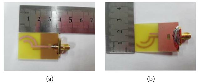
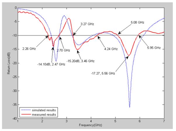
To evaluate the performance of the proposed antenna, an optimized antenna was fabricated, and its characteristics were measured using a network analyzer and an anechoic chamber. The prototype of the fabricated antenna is shown in Fig. 9, and the simulated and measured return losses are plotted and compared in Fig. 10. The measurement results were obtained using an Anritsu MS4644A vector network analyzer at Silla University in Busan, South Korea. The far-field radiation patterns and gains were measured using a far-field anechoic absorber obtained from Foxconn Corporation in South Korea. As shown in Fig. 10, the measured return loss characteristics were in good agreement with the simulated ones, therefore validating the accuracy of the HFSS simulation. However, a discrepancy was found between the measurement data and the simulation results. In the physical network analyzer measurement, the feeding mechanism of the proposed antenna was composed of an SMA connector and a microstrip line (the microstrip feed line was excited by an SMA connector), whereas the simulated results obtained using Ansoft HFSS showed that, by default, the antenna was excited by the wave port that was renormalized to a 50-Ω full port impedance. This discrepancy between the measurement data and the simulation results could be due to the effect of the SMA port. To confirm the accurate return loss characteristics of the designed antenna, it is recommended that the manufacturing and measurement process be undertaken carefully. It can be seen that the proposed antenna has three resonance frequencies located at 2.47, 3.46, and 5.56 GHz, respectively, to cover the three desired bands. The 10 dB impedance bandwidth of the measured return loss was found to be 440 MHz for the 2.4/2.5 GHz bands (from 2.26 to 2.70 GHz), 970 MHz for the 3.5 GHz bands (from 3.27 to 4.24 GHz), and 870 MHz for the 5 GHz bands (from 5.08 to 5.95 GHz). Thus, the antenna can cover the typical bandwidth requirements for the 2.4–2.484 and 5.15–5.825 GHz WLAN bands and 2.5–2.69, 3.4–3.7, and 5.25–5.85 GHz WiMAX bands, respectively.
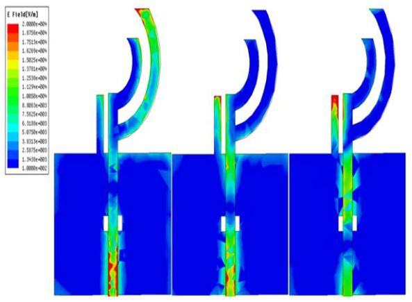
To understand the phenomenon behind this dual-band performance, the simulated current distribution for the proposed antenna at 2.56, 3.55, and 5.63 GHz are presented in Fig. 11. Fig. 11(a)-(c) shows the surface current density excitations along the circular-ring antenna for the three resonant frequencies (2.56, 3.55, and 5.63 GHz, respectively). As expected, it was clear that the different surface currents were excited by the 2.56, 3.55, and 5.63 GHz frequencies. As shown in Fig. 11(a), the lowest band surface current density excitations along the longest arc-shaped strip were observed when the resonant frequency was 2.56 GHz. This indicates that the 2.4/2.5 GHz band excitation is attributed to the longest arc-shaped strip. As noted in the 3.55 GHz band excitation in Fig. 11(b), a larger surface current density flowing along the vertical strip in the ground plane was observed when the resonant frequency was 3.55 GHz. Thus, the 3.5 GHz band excitation may be attributed to coupling the vertical strip and feed line. As shown in Fig. 11(c), however, larger surface current densities flowing along the vertical strip in the ground plane was observed when the resonant frequency was 5.63 GHz. Thus, the 5 GHz band excitation may be attributed to the vertical strip in the ground plane. Also, the 5 GHz band excitation was attributed to coupling of the vertical strip in the ground plane and feed line.
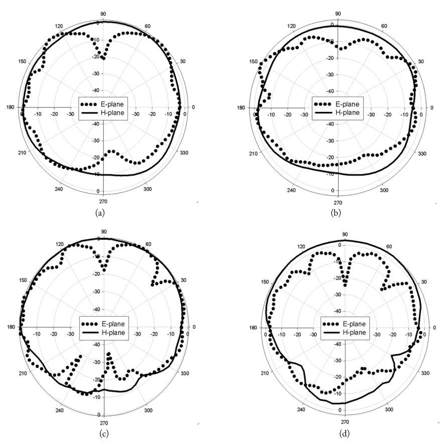
Fig. 12 shows the measured two-dimensional (2D) far-field radiation patterns in the E-plane (x-z plane) and the H-plane (y-z plane). Fig. 12(a)-(d) shows the 2D radiation patterns at 2,500, 3,500, 5,300, and 5,700 MHz, respectively. Based on these radiation patterns, the proposed antenna has omnidirectional radiation characteristics in the H-plane and monopolelike radiation pattern characteristics in the E-plane at the considered frequencies.
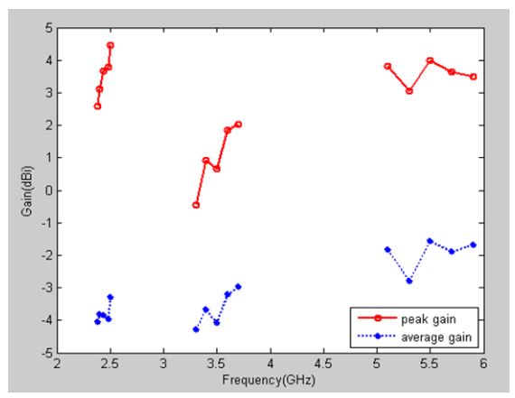
Fig. 13 shows the 2D measured antenna peak and average gain levels for the frequencies across the 2.4/2.5, 3.5, and 5 GHz bands. The 2.4/2.5 GHz band had a peak antenna gain level of 2.60 to 4.45 dBi, and the 3.5 GHz band, 1.2 to 2.04 dBi. The measured antenna peak levels in the 5 GHz band were 3.07 to 3.98 dBi. The 2.4/2.5 GHz band had an average antenna gain level of -4.05 to -3.29 dBi, and the 3.5 GHz band, -4.28 to -2.96 dBi. The measured antenna gain levels in the 5 GHz band were -2.78 to -1.55 dBi.
A novel planar monopole antenna with two arc-shaped strips, a vertical strip, and a slot in the ground plane for WLAN/WiMAX applications is proposed. The use of two arc-shaped strips enables the proposed antenna to yield two different resonances (2.5/3.5 GHz bands) to cover the desired bands. Also, the vertical strip in the ground plane enables the proposed antenna to yield 5 GHz band resonances to cover the desired bands. The rectangular slot in the ground plane enables the proposed antenna to yield impedance matching to cover the triple-band operation. In this paper, the findings of this parametric study on the proposed antenna, as well as the results pertaining to the surface current distributions of the operating frequencies, have been discussed. The measurement results show that the obtained impedance bandwidths are 440 MHz for the 2.4/2.5 GHz bands (from 2.26 to 2.70 GHz), 970 MHz for the 3.5 GHz bands (from 3.27 to 4.24 GHz), and 870 MHz for the GHz bands (from 5.08 to 5.95 GHz), which are suitable for WLAN and WiMAX applications. In addition, the proposed antenna has omnidirectional radiation characteristics and gains in the three operating bands.