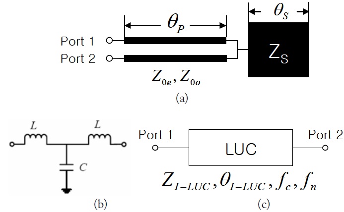
The parallel coupled line with an open stub (PCL-OS) in Fig. 1(a) has been reported and widely adopted as a building block or low pass filter unit cell (LUC) in designing a compact low pass filter [1], compact wideband bandstop filters [2,3], an harmonic and size reduced ring hybrid [4], and a compact and harmonic suppressed Wilkinson power divider [5]. The PCL-OS demonstrates excellent performances, including its low pass filter with wideband rejection characteristics and sharp skirt response as well as its structural compactness. The equivalent T-network and equivalent LUC block are represented in Fig. 1(b) and (c). The analysis of this PCL-OS was also attempted in [2,4,5].
However the derived analytical equations for the PCL-OS are approximated as an undefined floating port of the coupled line, which is connected to the open stub, is used as if a defined port in the analysis of the serially connected two-port networks in Fig. 2 of [2], Fig. 3 of [4], and Fig. 1 of [5]. The equivalent capacitance C in Fig. 1 was treated as a simple summation of the equivalent capacitance of the parallel coupled line (CP in [2,4,5]) and the equivalent capacitance of the open stub (CS). An even-odd mode analysis of the structure is also reported [3], which is limited in the transmission zeros with a quarter-wavelength for a bandstop filter design. When we design a microwave component that contains the PCL-OS or LUC using the previous equivalent equations, we have to perform repetitive iteration processes to obtain exact or desired characteristics.
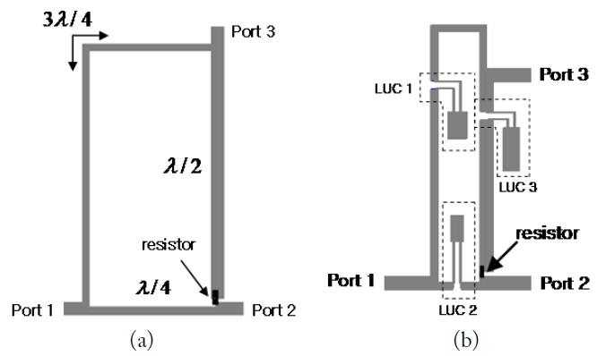
Meanwhile, a simple coplanar waveguide (CPW) balun having the structure of a Wilkinson divider has been recently proposed [6–8]. The balun consists of two 3λ/4 and λ/4 transmission lines with a λ/2 line with Z0 and a resistor with 2Z0. Hence, it has serious drawbacks in its size and unwanted harmonics for low frequency applications. The microstrip version of the Wilkinson balun is shown in Fig. 2(a).
In this research, we first derived the exact design equations for the LUC by applying the full even-odd mode analysis to the whole PCL-OS structure.
Second, to demonstrate the validity of the analysis we applied the design equations for the LUC to designing a size and harmonic reduced microstrip Wilkinson balun as shown in Fig. 2(b).
To analyze the PCL-OS structure we assumed that the structure is lossless and the discontinuity effect between the parallel coupled line and the open stub is negligible.
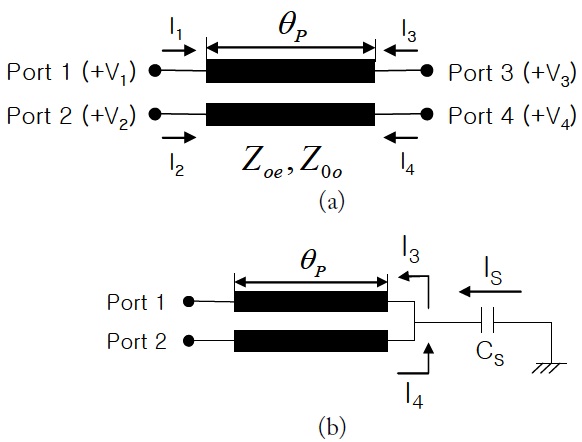
The characteristics of a parallel coupled line as shown in Fig. 3(a) can be expressed as an impedance matrix as follows [9],
where
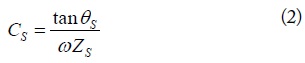
The open-stub section is modeled as an equivalent capacitor,

where
The relations between the node voltages and the branch currents around the connection point in Fig. 3(b) are given as (3a) and (3b) by Kirchhoff’s law.


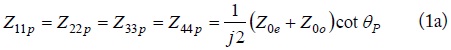
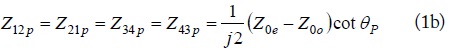
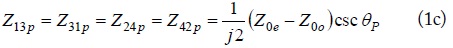
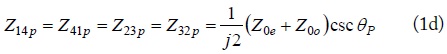
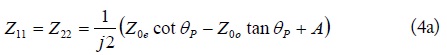
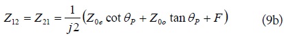
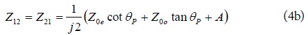
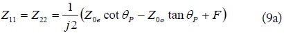
Using (3a)–(3b) and the well-known port reduction procedure the four-port impedance matrix, (1a)–(1d), can be converted into a two-port impedance matrix, (4a)–(4b).

where,
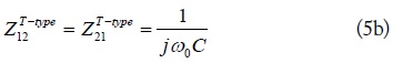
To design the three-stage low pass filter in Fig. 1(b) with a given specification of ripple and cutoff frequency
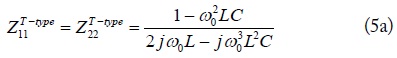

where
By equating (4) to (5), we can calculate the exact equivalent capacitance,
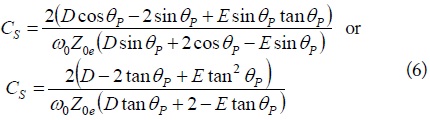
where
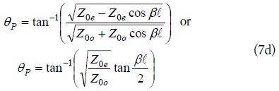
Now, we can decide the other structural parameters for the PCL-OS in Fig. 1(a), which performs the response for the desired low pass filter in Fig. 1(b), using the equivalent parameters for coupled line part of the PCL-OS from [1] and [9], as follows.

where
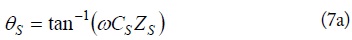
Meanwhile, the designed PCL-OS with low pass filter characteristics can be used to design various devices that have λ/4 transmission-line blocks or λ/4-LUCs. The λ/4-LUC is defined as an equivalent λ/4 line consisting of an LUC and two short transmission lines.
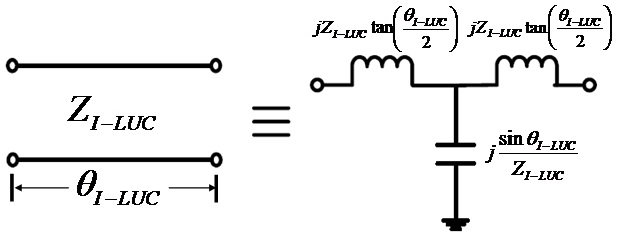
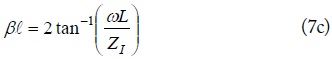
The image parameters of the LUC in Fig. 1(c) can be obtained as (8), equating the T-network in Fig. 1(b) with the T-type equivalent circuit for a transmission line in Fig. 4.

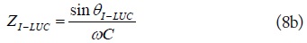
where

where
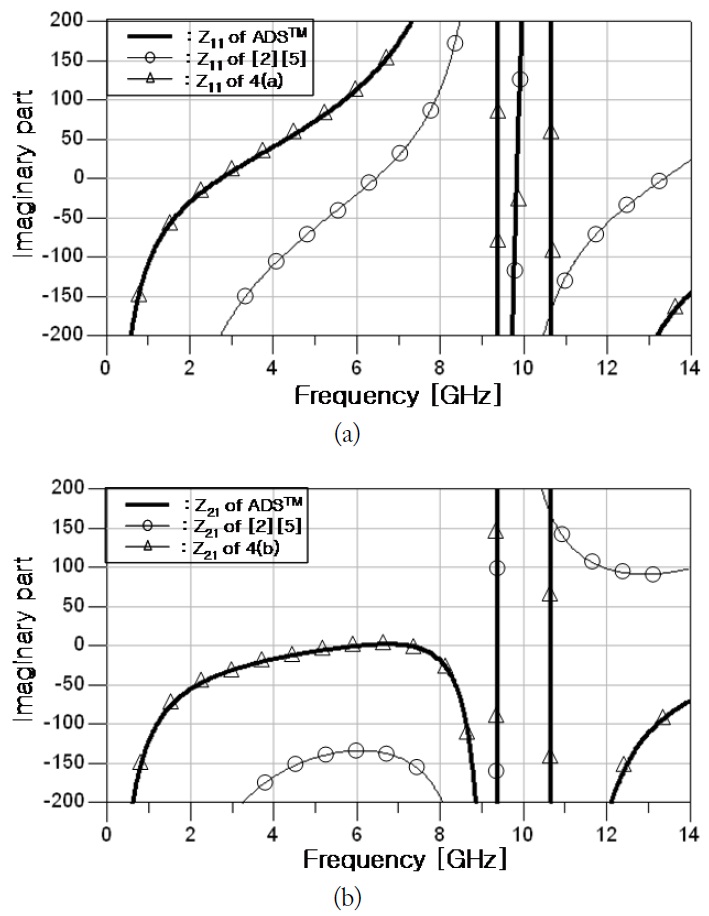
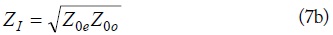
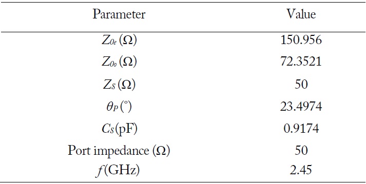
To compare the exactness of derived (4a)–(4b) with those previously reported, (1) of [2] or

Arbitrary parameter values for comparison of the parallel coupled line with an open stub (PCL-OS) design equations
The transmission zero frequency of notch frequency
From the relation [8] between the impedance and scattering matrices,
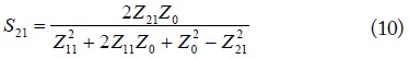
Then, the notch frequency
The notch frequency
III. MICROSTRIP WILKINSON BALUN DESIGN
Using the LUC design equations, we designed and fabricated a size and harmonics reduced microstrip Wilkinson balun operating at 2.45 GHz. Fig. 2(b) shows the layout of the proposed Wilkinson balun compared to the CPW-Wilkinson balun [6] of Fig. 2(a). Here, the transmission line sections of the Wilkinson balun are replaced by three LUCs. The LUC 1, 2, and 3 are good for harmonic reduction in
The LUC is designed using the following procedure:
We designed a T-type Chebyshev low pass filter with a cutoff of 2.45 GHz and a ripple of 0.01 dB. By using the obtained
[Table 2.] Parameter values of the LUCs for the balun design
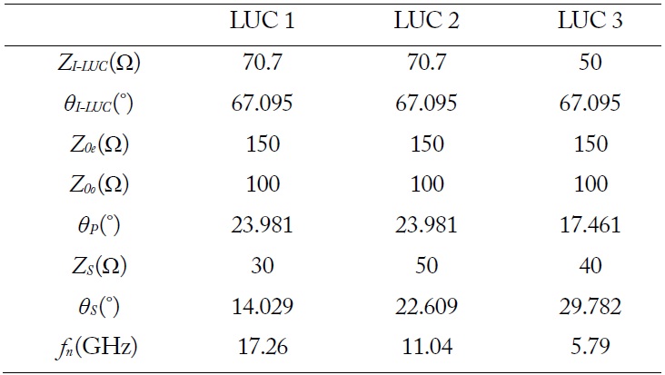
Parameter values of the LUCs for the balun design
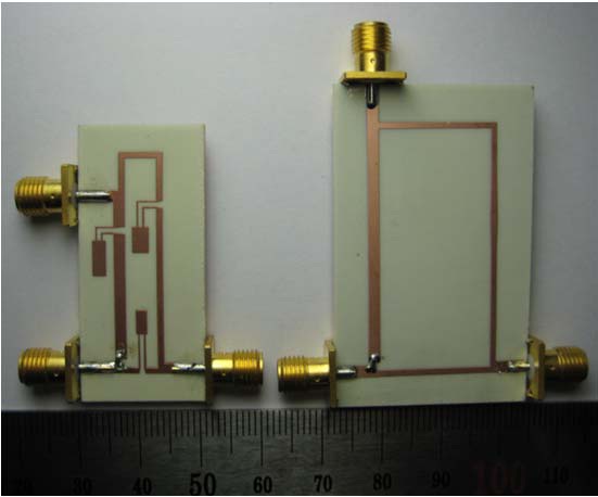
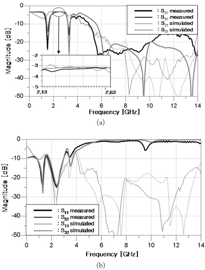
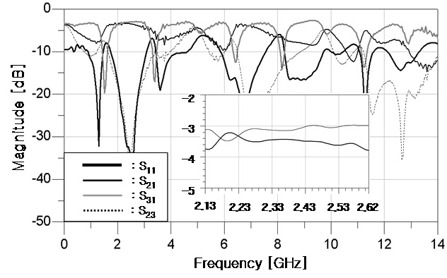
The power division, impedance matching, and isolation properties in a pass-band around 2.45 GHz are as good as a conventional Wilkinson balun. The thickness and relative dielectric constant of the WINUS ISO640-338 substrate used for the simulation and experiment is 0.762 mm and 3.38, respectively. Fig. 7 shows photographs of the proposed and a microstrip version of the conventional CPW-Wilkinson balun [6], which have the center frequency of 2.45 GHz. The area of the proposed microstrip Wilkinson balun is reduced to 48% of the conventional one. The simulated and measured amplitude results are shown in Fig. 8. They agree well with each other on the viewpoints of the power division, the matching, the isolation and the harmonic suppression properties. The measured insertion losses in
The exact analysis of the PCL-OS and an application of the Wilkinson balun are presented. The designed microstrip Wilkinson balun shows a significantly reduced size and a harmonicsuppressed property simultaneously, without degradation of the pass-band performances.
The proposed design equations and the LUC design procedure could be helpful in designing various microwave devices needing size reduction and harmonic suppression, simultaneously.

![(a) The microstrip version of [6, 7] and (b) the proposed microstrip Wilkinson balun.](http://oak.go.kr/repository/journal/15364/E1ELAT_2014_v14n4_387_f0002.jpg)


![Impedance parameter comparison for ADS, proposed (4a)?(4b), and equations in [2] and [5]. (a) Z11, (b) Z21.](http://oak.go.kr/repository/journal/15364/E1ELAT_2014_v14n4_387_f0005.jpg)