A simple realization of an alignment-free wireless power transmission (WPT) system is presented in this letter. The WPT system consists of a transmitter with three reconfigurable modes corresponding to various controllable magnetic field directions in the azimuthal plane and an algorithm for the optimum mode selection carried by sensing the reflected voltage of the system. Twelve light emitting diodes (LEDs) are used to confirm the on- and off-state of LEDs powered wirelessly by the transmitter at every 15° of the azimuthal plane. A criterion voltage from the reflected power of the system is found by using the correlation between the reflected voltage and the on- and off-state of the LEDs. Simply by continuous; monitoring of the voltage from the system, the system maintains power to the LEDs. The system is realized by MATLAB/Simulink and a National Instrument data acquisition device (DAQ) board. Measurements using the system show on-state LEDs in the azimuthal plane except at the angles of 60°, 75°, 180°, and 300°.
Wireless power transmission (WPT) based on magnetic resonance coupling is very attractive because of the many potential applications of this technology in electric vehicles, mobile charging systems, biomedical implants, etc. [1,2]. In the near future, WPT systems will have the capability to transfer power to anywhere in a 3-dimensional (3-D) environment regardless of the alignment between the receiver and transmitter. However, realization of a 3-D WPT system requires an alignment-free WPT system because the linkage magnetic flux would be zero in the orthogonal position between the receiver and the transmitter, resulting in zero WPT efficiency. One solution has been the proposal of a resonator with three modes, which can control the direction of the magnetic field in the azimuthal plane [3]. This resonator can reconfigure a mode using attached switches. Thus, an alignment-free system can be designed by controlling the switch combinations.
This letter presents a simple algorithm and realization of the alignment-free WPT system at 13.56 MHz. Essentially, the reflected power is sensed continuously from the system in order to determine which mode is to be optimized. The control system then changes the mode automatically to create an efficient WPT.
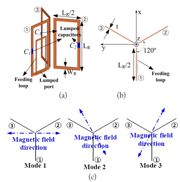
The transmitter is an alignment-free resonator, as shown in Fig. 1 [3]. The three modes are designed to have various mag-netic field directions: Mode 1 →
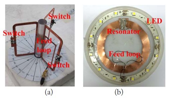
Fig. 2 shows a fabrication of the transmitter and receiver described above. The resonance frequencies of these resonators are measured as 13.69 MHz. Twelve light emitting diodes (LEDs) (1 W) are used in the receiver and a feeding loop connected to these LEDs is used to power the LEDs, as shown in Fig. 2(b) [3,4]. Note that the LEDs are turned on with a 13.56 MHz source. Thus, no rectifier is used in the receiver.
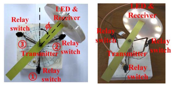
Fig. 3 shows the assembled transmitter and receiver. As also shown in Fig. 3, the relay switches are attached to each loop in the transmitter, so that the switches can be controlled by a bias voltage. For performance evaluation purposes, the assembled receiver is able to rotate the angle of
III. DESIGN OF ALIGNMENT-FREE WPT SYSTEM
In general, a coupler is used for monitoring the incident and reflected power of the system. Thus, in the alignment-free WPT system, the coupler is useful for checking the system return loss. Sensing of the system return loss is implified by designing and connecting a half-wave rectifier to the coupler to measure the reflected power. At this time, the 13 dB coupler is used in the measurement.
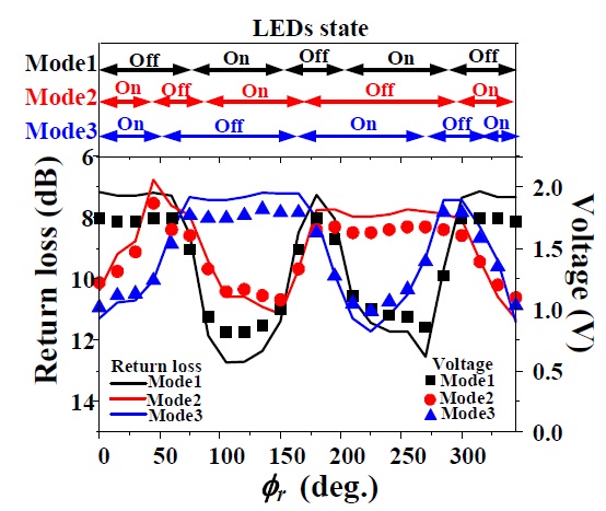
The return loss, the voltage of the reflected power from the coupler, and the on- and off-state of LEDs are measured and checked to determine the correlation between the reflected power and the state of LEDs at a distance of 10 cm. The power amplifier with a gain of 43 dB is used and its output power is set at 4 W. Fig. 4 shows the correlation of the state of the LEDs and the return loss, including the voltage from the reflected power at every 15° of
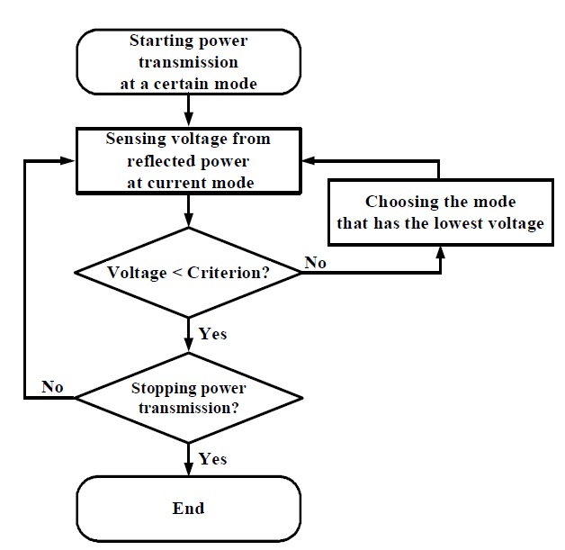
Fig. 5 depicts a flow chart of a simple algorithm for optimum mode selection. As stated above, when the voltage of the reflected power is higher than the criterion value of 1.49 V, the process of the optimum mode selection is carried out by choosing the mode that has the lowest voltage value. This algorithm is realized by using the National Instrument (NI) data acquisition (DAQ) board and the MATLAB/Simulink [5] in the alignment-free WPT system, as shown in Fig. 6. The measured voltage of the rectifier is obtained from the analog-todigital convertor (ADC) of the DAQ board and the MATLAB/Simulink compares the attained voltage and the criterion voltage. If a mode change is needed (in the case of a higher voltage than the criterion), the MATLAB/Simulink then acquires the voltages at the other modes and chooses the optimum mode that shows the lowest voltage. By controlling the bias voltage of the digital-to-analog convertor (DAC) of DAQ board, the MATLAB/Simulink sets the optimum switch combination for the selected mode.
The alignment-free WPT is verified by conducting the measurement with the designed system, as shown in Fig. 6. The measurement confirms that the LEDs are turned on in the azimuthal plane except at the angles of
This letter presents an alignment-free WPT system with three reconfigurable modes for magnetic field control. A simple algorithm for choosing the optimum mode is proposed by using the criterion voltage of the reflected power. In addition, a simple system realization is proposed with MATLAB/Simulink and a NI DAQ board for real time control of the mode. As a result, wireless powering to the LEDs is confirmed in the azimuthal plane. The designed alignment-free WPT system is viewed as potentially useful in future 3-D WPT systems.